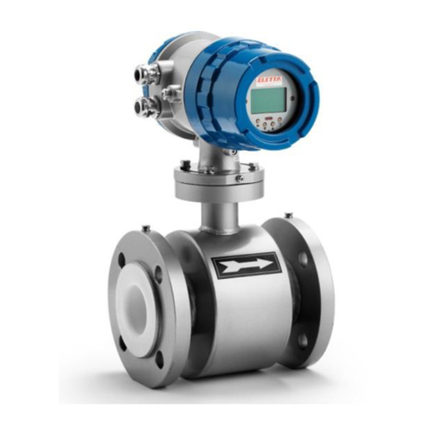
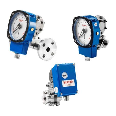
Eletta V Series User manual

1 40 2E1
1 40B2E12
Manual
Eletta Flow Monitor
V-series
Models
V1 and V1
5
2021-12-06
40G2E22

2
40G2E22
About this Manual
• This manual relates to the V-series Flow Monitor.
• Note that the latest version of this manual is always available as a PDF file on our
web site www.eletta.com
• On our web site you also find other interesting information such as leaflets,
newsletters and application reports.
Proprietary Rights
This manual contains confidential technical data, including trade secrets and
proprietary information, that are the property of Eletta Flow AB, Sweden.
Any changes or alterations to downloaded or printed Eletta original documentation such
as manuals, drawings, leaflets, newsletters, etc. are not permitted without a written
permission from Eletta Flow AB, Sweden.
These data are only disclosed to you under permission of limited use within your
company. Use for manufacturing or processing is not permitted.
Any other use of data and information is strictly prohibited without prior written
permission from Eletta Flow AB, Sweden.
Distributors
Eletta has appointed a number of distributors all over the world. You will find
more information about your closest distributor at our web site
www.eletta.com, or by contacting our Customer Service Center.
Customer Service
Phone +46 8 603 07 70 Switchboard
+46 8 603 07 80 Orders and Inquires
Postal Mail Eletta Flow AB
P.O. Box 5084
SE-141 05 Kungens Kurva
SWEDEN
Web www.eletta.com

3
40G2E22
Contents
General Information 4
1.1 Description 4
1.2 Specifications 10
Installation 13
2.1 Unpacking 13
2.2 Procedures before installation 13
2.3 Installation of the Pipe Section 14
2.4 Separate mounting of Pipe Section and Control Unit 15
2.5 Installation and changing of the Control Unit 17
2.6 Pressure drop 19
2.7 Electrical installation 21
Operation 23
3.1 Principle of operation, DP-Flow Measurement 23
3.2 Change of Flow Range 23
3.3 Change of Flow Direction 25
3.4 Adjustment of switch point 26
Trouble shooting 27
4.1 Verification of flow 27
4.2 Electrical connections 29
4.3 Spares 29
Tables 30
5.1 Measuring ranges 30
5.2 Weight and dimensions 31
Spare parts 33
6.1 Exploded drawing V-GL/FA 33
6.2 Exploded drawing V-GSS/FSS 35
6.3 Exploded drawing VSS-GSS/FSS 37
Distributors 38
Recycling 38

4
40G2E22
1.1Description
The Eletta Flow Monitor is used to control and measure flow of liquids and
gases in pipes from size 15 mm to 500 mm (larger pipes as an option). They
have been manufactured for over 70 years and are well known for its reliabili-
ty.They are used where operational safety demands, efficient supervision and
rugged installation is needed, all over the world. Eletta Flow AB in Sweden is
certified according to ISO9001 and ISO14001.
The Eletta Flow Monitor is based on the proven and dependable differential
pressure principle, using interchangeable orifice plates for different measu-
ring ranges. The Flow Monitors are working with different differential
pressure ranges, i.e. 12,5 –50 and 50 –200 mbar for the V1, V1SS and
22 –550 mbar for the V15, V15SS depending on the desired and ordered
flow range. The same goes for our models; D2/D2SS/S2/S2SS and
D5/D5SS/S25 and S25SS. Due to the working principle of the instrument, it
is of utmost importance that the installation instructions (chapter 2) are
followed carefully in order to get the proper function of the instrument.
The Eletta Flow Monitor models V1, V1SS, V15 and V15SS will give you a
repeatable switch point of < 2% if installed in the right way. (See chapter 1.2
“Specifications”, for complete information.)
The Instrument consists of two parts mainly i.e. the Pipe Section and the
Control Unit. The Pipe Section is the part that is to be mounted in the process
pipe and the Control Unit is mounted directly (standard) or remote on/to the
Pipe Section. The Control Unit contains the micro switch (SPDT) and the
electrical connection terminal block. It also contains the mechanical adjusting
dial where you change the setting of the flow alarm trippingpoint.
The Pipe Sections are available in different process connections with the fol-
lowing standards;
Threaded connections in BSP or NPT from 15 mm (1/2”) to 40 mm (1 1/2”)
depending on the chosen material of construction.
Flanged (wafer) connection from DN15 /PN16 (ANSI 1/2”/150 lbs) to DN
500/PN16 (ANSI 20”/150lbs) depending on the chosen material of construc-
tion.
The Control Units V1, V1SS, V15 and V15SS are equipped with one, freely
adjustable over the whole ordered flow range, micro switch, which can be
set for low/high flow alarm.
General Information
1

5
40G2E22
Product label
Each of our flow monitors wear a product label, see picture below with description.
•Type: Model type of the flow monitor. For example V15-GL15. Reference to
section 1.2 Specifications for a thorough description of available types.
•Temp: The maximum operation temperature allowed for the control unit.
Reference to section 1.2 Specifications for a thorough description of available types.
•Range: The flow range for which the flow monitor have been manufactured.
•Max Pressure: The maximum operation pressure allowed for the flow monitor.
•Liquid: The media which the flow monitor have been designated for.
Examples: Water, oil etc.
•Protection class:IP -classification (Internationalprotection rating), of the controlunit.
•Model: The article number of the flow monitor.
•Std: Pipe standard for which the flow monitor is designated. For example: DIN
PN16, Dimensions according to DIN and pressure classification according to PN16.
•No: Serial number of the flow monitor. Each of our flow monitor have theirown
unique id number, which is used for traceability.
•Year of manufacturing.
1

6
40G2E22
2.
3.
Ex versions
The Ex versions of flow monitors of type V1 and V15 are designed to be used in ex-
plosive atmospheres. The monitors are approved according to the IECEx certification
scheme as an intrinsically safe apparatus according to standards IEC 60079-0:2007,
IEC 60079-11:2007 and IEC 60079-26:2006.
According to the ATEX directive (94/9/EC) the monitors of type V1 and V15 are
considered as “simple apparatuses” according to EN 60079-11:2006. The monitors
contain mechanical parts that move slowly and with low power input, incapable of
forming hot surfaces or other ignition sources even in cases of rare malfunction. The
ATEX directive is not applicable for “simple apparatuses” or for slow moving mecha-
nical parts with low power input. The monitors have been designed and examined as
simple apparatus according to EN 60079-0:2009, EN 60079-11:2006, EN 60079-26:
2007 and EN 13463-1:2009.
The explosion protection is based on normal atmospheric pressure (0,8-1,1 bar),
normal oxygen content (21 % v/v) and minimum ambient temperature -20 °C. For
maximum ambient temperature see section 1.2 “Specifications”.
Information in the manual concerning our Ex versions will be marked with:
in the margin.
Ex label
Our Ex approved flow monitors wears an Ex label which defines the explosion pro-
tection code and the Intrinsically safe parameters to be used, see picture below with
description.
1. Explosion protection code. All our Ex versions of the V-series are approved for
•ia = Intrinsically safe equipment to be used in Zone 0.
•IIC = Explosion code for flammable and explosive gases; Hydrogen,
acetylene, carbon disulphide
•T? Temperature classification = Indicates the maximum surfacetemperature
of the equipment. Reference to table 5 in section 1.2 Specifications, for
available Temperature classes.
•Ga = Equipment classified for gases in Zone0.
2. Certificate ID: The type examination code of the equipment.
3. Intrinsically safe parameters of which the flow monitor should be connected. Reference
to 2.7 Electrical installation.
1
Ex
Ex
1.

7
40G2E22
Type ID of our Ex versions
V1 or V15
Pipe dimension
Type
DIN PN16
ANSI 150lbs
-FA15-Ex
DN 15
½”
-FA20-Ex
DN 20
¾”
-FA25-Ex
DN 25
1”
-FA32-Ex
DN 32
1 ¼”
-FA40-Ex
DN 40
1 ½”
-FA50-Ex
DN 50
2”
-FA65-Ex
DN 65
2 ½”
-FA80-Ex
DN 80
3”
-FA100-Ex
DN 100
4”
-FA125-Ex
DN 125
5”
-FA150-Ex
DN 150
6”
-FA200-Ex
DN 200
8”
-FA250-Ex
DN 250
10”
-FA300-Ex
DN 300
12”
-FA350-Ex
DN 350
14”
-FA400-Ex
DN 400
16”
Table 1.
V1 or V15
Type
Pipe dimension
-GSS15-Ex
DN15 (G ½” / NPT ½”)
-GSS20-Ex
DN20 (G ¾” / NPT ¾”)
-GSS25-Ex
DN25 (G 1” / NPT 1”)
Table 3.
V1 or V15
Pipe dimension
Type
DIN PN16
ANSI 150lbs
-FSS15-Ex
DN 15
½”
-FSS20-Ex
DN 20
¾”
-FSS25-Ex
DN 25
1”
-FSS32-Ex
DN 32
1 ¼”
-FSS40-Ex
DN 40
1 ½”
-FSS50-Ex
DN 50
2”
-FSS65-Ex
DN 65
2 ½”
-FSS80-Ex
DN 80
3”
-FSS100-Ex
DN 100
4”
-FSS125-Ex
DN 125
5”
-FSS150-Ex
DN 150
6”
-FSS200-Ex
DN 200
8”
-FSS250-Ex
DN 250
10”
-FSS300-Ex
DN 300
12”
-FSS350-Ex
DN 350
14”
-FSS400-Ex
DN 400
16”
-FSS450-Ex
DN 450
18”
-FSS500-Ex
DN 500
20”
Table 2.
V1 or V15
Type
Pipe dimension
-GL15-Ex
DN15 (G ½” / NPT ½”)
-GL20-Ex
DN20 (G ¾” / NPT ¾”)
-GL25-Ex
DN25 (G 1” / NPT 1”)
-GL40-Ex
DN40 (G 1 ½” / NPT 1 ½”)
Table 4.
Note!: The control unit may be delivered without a mounted pipe section, in case a unit need to be
replaced. The type designation on the product label of the control unit then applies for the complete
assembled Flow monitor (control unit and pipe section) according to tables above. An Ex version
control unit should only be mounted with a pipe section in accordance to the information on the
product label.
1
Ex
Ex

8
40G2E22
Special conditions for safe use
1The blue enclosure and surfaces of the control unit are made of aluminum. This light
metal part shall not be subject to impacts or friction in order to avoid sparks.
2The process connection to the Flow monitor must be performed to be sufficiently sealed
between the inside and outside of the process connection (IP67).
3To avoid electrostatic charging of the enclosure the internal earth connection must be
connected to earth.
4The ambient temperature range for the equipment deviates from the standard range.
The temperature class for the equipment depends on the ambient temperature.
See table 5 in section 1.2 Specifications, page 12.
1
Ex

9
40G2E22
1.2Specifications
The only difference between the V1, V1SS, V15 and V15SS is the turn down
of the flow range i.e. the V1 has a 1:2 turn down (for example; 50 –100
l/min) and the V15 has a turn down of 1:5 (for example; 40 –200 l/min).
Repetability: <+/-2% of actual pre-set tripping flowvalue.
It is recommended that you always chose the Flow Range of
the Flow Monitor so that the normal flow is in the middle of
the Monitor Flow Range. Make sure that the expected alarm
set points is within the chosen flow range.
For example: If you have a flow of 110 l/min maximum and
the normal Flow is at 90 l/min, choose the Eletta Flow
Monitor V1 with a Flow Range of 60–120 l/min.
Pressure: Max:16 bar, (232 PSI), higher test pressure as an option.
Min: A line pressure of appr. 0,7 –1,0 bar is required for pro-
per operation.
Temperature: ControlUnit
-20°C to 90°C, standard
-20°C to 120°C (12°F to 248°F), option
Recommendation of choice of rubber material:
Rubber material
Min T °C
Max T °C
Nbr
-20
80
Epdm
-40
100
Fpm
-10
250
Higher process temperature possible with remote installation
of Control Unit (separate mounting, see section 2.4).
Pipe Section:
The pipe sections (GL all sizes and FA 40 mm 100 mm) are
equipped with spacers holding the orifice plate made of
Polyamide plastic (PA) material and they can handle liquid/gas
temperature up to 150°C (302°F). For higher process tempera-
ture, we recommend to use the stainless steel pipe section,
which has no spacers. See spacers p. 11.
Our Ex versions are all equipped with spacers in stainless steel.
1
Ex

10
40G2E22
IP43 (NEMA 3 R), standard
IP65 (NEMA 4), optional
Aluminum alloy, alodine and epoxy polyester coated 1
off cable gland of nickel-plated brass included.
VAC
Process connection:
DN15 –40 (½” – 1 ½”) for GL-models
DN15 –25 (½” – 1”) for GSS –models
DN15 –400 (½” – 16”) for FA-models
DN15 –500 (½” – 20”) for FSS-models
Control Unit:
Optional Local Indication:
There is no local readout of the flow or flow set value in the V-series Flow Moni-
tor. However, there is an ”Indication window” which can be mounted in the cover
of the Control Unit and this can be ordered as an option. This feature indicates
roughly how the is which makes it easy to check if there is a flow or not.
The ”Indication window” is not to be used as an accurate measurement indication
of the flow. If you need an accurate and direct reading Flow Monitor, we recom-
mend the S-series Flow Monitor with a large and easy visible 135 mm (5,3”)
diameter dial. The V-series can be upgraded in the field to an S-series with local
indication. Please contact Eletta Flow for advice.
Note: Local indication is not available on our Ex versions.
Alarm indication:
On the V-series there is no visible micro switch indication to indicate if the switch
is on or off. This feature can be ordered as an option as LED-indication on the side
of the Control Unit.
Note: LED indication is not available on our Ex versions.
Micro switch spec:
Standard versions - Contact surfaces are silver plated
Hystereses: ca. 10%
Voltage: max. 460 VAC
Current: max. 15 A
Inductive load: 0,02A @ 230 VDC
0,03A @ 125 VDC 1A @ 30 VDC Type: SPDT
Ex versions - The contact surfaces of the micro switches are gold plated, suitable
for the lower voltage and currents of intrinsically safe circuits
Hystereses: ca. 10%
Voltage: max. 125 VAC
Current: max. 1A
Inductive load: 0,5 A @ 28 VDC
Type: SPDT
1
Ex
Ex
Ex
IP65 (NEMA 4), standard
Aluminum alloy, alodine and polyester powder coating.
1 off cable gland of nickel-plated brass included.

11
40G2E22
Material; Diaphragm housing and pipe section:
Type GL: De-zincificated brass, CW602N, EN12420
Type GSS: Seaworthy stainless steel 1.4470
Type FA: Housing: De-zincificated brass, CW602N, EN12420
Pipe section: Powder coated (20220096997096) steel, 1.0060/E335/SS1650.
Type FSS: Housing: Seaworthy stainless steel1.4470
Pipe section: Stainless steel 1.4435
Material diaphragm, O-rings and sealings:
• Textile reinforced Hydrated Nitrile rubber (HNBR), standard on all models except
stainless steel.
•Textile reinforced EPDM rubber, optional for all models.
•Textile reinforced Fluorinated rubber, FPM, standard in stainless steel
models, optional for others.
Spacer: The spacer holds the orifice plate inside the pipe section.
GL pipes: Polyamide plastic (-10 to 120°C (14 to 248°F):
FA pipes: DN15-100 Pylyamide plastic (-10 to 120°C (14 to 248°F)
DN125-400 stainless steel EN1.4404
Our Ex versions are all equipped with spacers in stainless steel.
Intrinsically Safe Data (valid for our Ex versions only):
The flow monitor is a part of an intrinsically safe circuit
according to below data:
Ambient temperature ( Tamb ): Must not exceed the maximum temperature of the
medium according to table x below.
Intrinsically safe circuit:
Code for explosions protection: Ex ia IIC T* Ga
* according to table x below
Maximum input voltage (Ui): 28,0V
Maximum input current (Ii): 100 mA
Maximum input power (Pi): 1,20W
Maximum internal capacitance (Ci): 1 nF
Maximum internal inductance (Li): 10 μH
1
Ex
Ex

12
40G2E22
Relation between medium temp and Temperatur class.
Maximum temperature of the
medium through the pipe section
of the Flow monitor (°C)
Temperatur class
100
T4
70
T5
60
T6
Table 5.
CE-
approvals: The Eletta Flow Monitors conforms with the EU directive for
low voltage no: 2014/35/EU. We refer to the certificates issued,
which will be sent to you upon request. They can also be found
on www.eletta.com.
PED-
Directive: Complies with applicable parts in Pressure Equipment Directive
2014/68/EU. Conformity assessment has been performed
according to module A. Internal production control combined
with module A2. Internal manufacturing checks with monitoring
of the final assessment, for category 2. Performed by Kiwa
Inspecta AB. PED Declaration of conformity will be sent to you
upon request and are also available on www.eletta.com.
1
Ex

13
40G2E22
2.1 Unpacking
We appreciate that you have decided to purchase our Products and we would like to
ask you to begin the installation by checking your delivery against the Packing List.
Please make sure to check the box for external damages before opening. If you find
external damages, which have also led to damages to the Flow Monitor inside, you
should contact the forwarder/shipper to claim replacement (or the cost of replace-
ment). Check the Monitors’ identification tag against your purchase order to make
sure you have got the right articles with the right specifications.
The packing material is made out of recycled environmental friendly material and
we kindly ask you to deal with the waste material in a way that will have as little
impact to the environment as possible.
2.2 Procedures before Installation
Note! Installation and maintenance of Ex versions should be executed according to
applicable national laws and regulations. Within EU, directive 1999/92 EC should
be considered. EU members within CENELEC should consider the requirements
within national standards, based on EN-60079-14 and EN60079-17.
Note!!! Before any installation or maintenance work, disconnect all electrical power!
Please check that you are going to mount the Monitor at the lowest point in the
piping system if you are measuring liquids and at the highest point if you are mea-
suring gases. Also check if the planned flow direction in the system matches the one
indicated on the Monitor. There is a red flow direction arrow on the outside of the
pipe section (not the Stainless Steel-models which have a marking engraved on the
side). If you find this to mismatch, we refer to section 3.3 ”Change of Flow Direc-
tion”, to adjust the internal flow director in order to match the desired flow direction.
Change of the flow direction on our Stainless Steel Pipe Sections (FSS/GSS) is not
possible in the field without ordering a new Pipe Section and we kindly ask you to
contact your local representative or Eletta Flow AB, Sweden for help.
Check that the pipe section has the right threads or the right flange standard to match
your piping or counter flange. If you are using the separate/remote execution i.e.
Pipe Section and Control Unit installed in different locations,
Installation
2
Ex

14
40G2E22
Installation of Pipe Section
please check the plastic hoses for any damages or holes that can prevent proper fun-
ction. The plastic hoses should not be used in temperatures over 90ºC/16 bar (194
ºF/232 PSI). If your application temperature exceeds this temperature/pressure, we
recommend to use copper or stainless steel tubing, depending on the compatibility
to the measured gas or liquid (see section 2.4)
Note: Remote/separate execution is not available on our Ex versions.
2.3 Installation of the Pipe Section
Note!!! Before starting to install the Pipe Section, please make sure that the piping
is not under pressure from flow of liquid/gas!
The pipe section can be installed in any desired direction, vertically or horizontally
and the direction arrow on the pipe section denote the direction of the flow. It is very
important that the pipe section is mounted with the correct direction, as the function
of the Flow Monitor otherwise will be prevented. The piping shall be rigid and free
from vibrations and hoses connected directly into the Monitors should be avoided
as much as possible. If you have weak piping we advise you to use the M6 moun-
ting hole (only on GL-series) on the backside of the pipe section, to fasten the pipe
section to a wall or a rigid bracket. The straight runs before and after the Monitor
should not be to short, in order to avoid disturbances, which can cause the Monitor
to show incorrect values. We recommend giving at least 10-15 diameters upstream
and 5 diameters downstream.
(Please see Fig. 1)
The reasons for this procedure is to achieve a stable flow profile inside the pipe
and by doing so, get a true reading. Please be aware of the fact that it is practically
impossible to predict when the flow is stable after disturbances in the piping, so this
must serve as a guideline only.
2
Recommended installation of Pipe Section
Ex
Fig. 1

15
40G2E22
Ex
The following inside diameters apply for the threaded Pipe Sections: GL- and
GSS 15 = 16 mm GL- and GSS 20 = 21 mm GL- and GSS 25 = 26 mm
GL-40 = 41 mm
The straight runs must be free from valves, bends or in/decreasing diameters. Any of
these disturbances must be placed before and preferably after you start counting the
straight runs.
Make sure that the Control unit, if mounted directly on the pipe section, is placed on top
of the pipe section and not under to prevent particles in the fluid to collect in the
diaphragm housing. Please consider using a filter in the pipeline if you suspect the fluid
to contain particles.
The flanged models, FA and FSS-versions, must be aligned with the counter flange and
not placed in stress by tightening the bolts uneven. The flanged models come with a
gasket and we recommend using this, as it is dimensioned to suit the installation. Please
see to that the packing is properly aligned and not disturbing the flow. It is also of
utmost importance that the connecting pipe and flange is of the same diameter (inside)
and standard as the pipe section. A mismatch can cause an erratic or incorrect reading of
the flow. If needed, please support the Flow Monitors with rigid brackets. There is no
problem in attaching the brackets directly to the Flow Monitor (see above), but we re-
commend mounting them in the pipeline downstream and upstream to avoid
unnecessary stress in the installation area.
2.4 Separate mounting of the Pipe Section and the ControlUnit
Ex .Note!: Remote/separate execution is not available as Ex versions.
Sometimes separate mounting of the Pipe Section and the Control Unit is requested due to
vibrations, high temperature or lack of space. As the Eletta Flow Monitor is using the
differential pressure caused by the orifice plate mounted in the pipeline and directs these two
pressures via two individual ports up to the Control Unit, it is also possible to separate the
2
If you are installing the threaded versions, GL and GSS-versions, please make sure
that you are not using so called ”tube fittings”. We have often seen them to have a
much smaller inside diameter than the pipe section, even though the size of the
thread match. This can create a jet stream of the fluid or gas, which will cause the
differential pressure to be to low and you, will not get a good or accurate reading.
The following inside diameters apply for the threaded Pipe Sections:
GL- and GSS 15 = 16 mm
GL- and GSS 20 = 21 mm
GL- and GSS 25 = 26 mm
GL-40 = 41 mm

16
40G2E22
Monitor into two parts. The pressure is then lead through either plastic hoses
or metallic tubing depending on the liquid, pressure and temperature. As a
standard, we supply 2x1,75 meter (5.74 feet) of PA plastic, Ø 6 mm (0,23
inch) hoses capable of handling 90ºC (194°F) and 16 bar (232 PSI), together
with two specially made adapters to be mounted on the Pipe Section and
Control Unit respectively. If your application requires metallic tubing (copper
or stainless steel) it has to be provided locally. If you are measuring a
chemical liquid or gas, check with the supplier which material you should use
in your tubing. Please make sure to use only 6 mm tubing in order to suit the
tube fit- tings included in the delivery.
There is no actual limitation in the length of the hoses or tubing, but we re-
commend placing the units as close as possible to each other, as this will help
in troubleshooting and on-site calibration.
Note!!! The hoses/tubings must have the same length to avoid uneven pres-
sure. If you mount valves (not included in delivery) in the pressure hoses/tu-
bing, it will help you to easily shut them off and remove/exchange the
Control Unit at full process pressure.
The Mounting of three-way/five-way standard valve (not included in delivery)
will allow you to discharge any entrapped air/gas or condense and also provi-
de the possibility to even out the pressure between the plus and minus leg for
zero verification.
Please follow the above ”Installation of the Pipe Section” after you have
mounted the adapter on to the Pipe Section. As you will use hoses/tubing to
lead the pressure up to the Control Unit, it is possible to mount the Pipe
Section in any direction, vertically or horizontally and with the pressure ports
pointing up, down or to the side (pls. see to section 2.3).
Separate mounting of Pipe Section and Control Unit GL/FA
2
Fig. 2

17
40G2E22
If you, for example, would like to upgrade a V-or S-series with mechanical micro switches to a
D-series including analog output, local front display with a bar graph and two independent adjus-
flow range you need, to get the right dial with the right multiplier or direct reading scale.
Separate mounting of Pipe Section –GSS/FSS
Purge valve
Hose/ Adapter for Controlunit Pipe
Tubing Adapter for pipe section fitting
Find a suitable place for the Control Unit to be mounted. Use the supplied bracket to attach it
to a wall, pipe or another steady and rigid support. Totake advantage of the large and clear
dial, the Control Unit should be clearly visible from a distance and easy accessible for
maintenance if needed. Please plan this with respect to later mounted piping or other
obstacles.
Install the hoses/tubing, commencing with the Pipe Section. Check that you have enough
length to cover the distance between the Pipe Section and Control Unit. The Pipe Section
adapter has a (+) and (–) marking engraved and the adapter on the Control Unit too. Please
make sure to match (+) to (+) and (–) to (–) on the adapters. Press the hose/tube end into the
coupling and tighten with care. Proceed to the Control Unit and repeat the above. When you
fill up the system for
the first time with liquid, please make sure that all entrapped air in the piping between the
Pipe Section and Control Unit is removed. The air can otherwise, as it is a compressible
media, cause faulty Flow readings.
2.5 Installation and changing of the Control Unit
As all Eletta Flow Monitors are designed in sections to achieve a modular and versatile
Flow Monitor, there is a possibility to upgrade/rebuild them and adding other features to
your already installed Monitor, by changing the Control Unit or Pipe Section.
Note!: Equipments which are Ex product are only allowed to be exchanged with other Ex product.
2
If you, for example, would like to upgrade a V-or S-series with mechanical micro switches to a
D-series including analog and/or frequency output, local front display and two independent
adjustable relays or the other way around, this is easily done. es
Yousimply order a Control Unit with the flow range you need.
Ex
Fig. 3

18
40G2E22
When you order, you will get the Control Unit with the diaphragm housing
included. Make sure you order the right material in the diaphragm housing
and the soft rubber parts (diaphragm, o-rings and diaphragm lever) and you
will get the Control Unit already tested and calibrated and ready to fit onto the
Pipe Section, without any on-site adjustments or calibration. All Eletta DP
Flow Monitors are working with the same differential pressure within their
specific range (Pls. see section 1.1).
As an option we have a manifold with shut-off valves, this enables you to
dismount the control unit from the pipe-section during full operation.
Start with making sure that there is no pressure in the system. Turn the
electric power supply off
and then disconnect the cables from the microswitch
electric terminal.
On the -GL Pipe Section; loosen the four (4) hexagon screws that hold the
diaphragm housing (do not remove the blue housing at any time) to the Pipe
Section. Replace the flow direction selector (3.3) if damaged, or
if other material is required. Install the new Control Unit and tighten the four
(4) hexagon screws firmly again.
On the -GSS Pipe Section; loosen the two (2) hexagon screws that hold the
diaphragm housing and replace the O-rings to the right material, if necessary.
Install the new Control Unit and tighten the two (2) screws firmly again.
On the -FA Pipe Section; loosen the four (4) hexagon screws that hold the
diaphragm housing to the pipe section (do not remove the blue housing at any time)
Replace the flow direction selector (3.3) if damaged, or if other
material is required. Install the new Control Unit and tighten the four (4) hexagon
screws firmly again.
2

19
40G2E22
The permanent pressure drop can be calculated approximately by Δρ (ppd) = Δρ
(apd)(1-β 2), where the symbols represent:
Δρ (ppd) = permanent pressure drop Δr(apd) = actural
pressure drop foir a certain flow
Please see below formula for calculating actual pressure drop.
Δρ = differential pressure flow measurement and β= d/D ratio (ratio between bore and
inner diameter of the pipe). This means that for the normal βrange (0.2 - 0.7) a typical
permanent pressu
re loss ranges from 0.96 Δρ and 0.51 Δρ can be expected.
foir a certain flow
On the -FSS Pipe Section; Loosen the two screws that hold the diaphragm housing
and replace the O-rings to the right material, if necessary.
Install the new Control Unit and tighten the two screws firmly again
Connect the electrical cables according to your new Control Unit’s possibilities and for
detailed information regarding wiring, please see section 2.7 ”Electrical installation”.
2.6 Pressure Drop
The Eletta Flow Monitor is a differential pressure measuring device and therefore it
creates a certain pressure drop when in function. There are two different types of
Pressure Drop’s involved, actual pressure drop and permanent pressure drop.
Below we will explain the difference between these two: When the orifice plate
mounted in the Eletta Flow Monitor reduces the flow area inside the pipe system, a
pressure drop over the orifice is created. This is what we call actual pressure drop.
Please refer to chapter 1.1 ”Description” for actual pressure drop (differential
pressure span).
The calculation of the flow is using this pressure drop to calculate the actual flow value
(see calculation below). The actual pressure drop is a temporary pressure state and
the Eletta Flow Monitors are working within this differential pressure created within
the Flow range of the Monitor. When the flow has passed the Monitor, the pressure is
then trying to get back to its original pressure and normally after 10 - 15 times the inner
diameter of the pipe, the flow becomes linear and fully developed. This is a normalized
flow but due to friction losses over our Flow Monitor, the pressure will not be able to
reclaim all the energy (pressure). This is what we call permanent pressure drop.
2
The permanent pressure drop can be calculated approximately by (ppd)=
(apd)(1-2), where the symbols represent:
(ppd)=
r(apd) =
permanent pressure drop
actural pressure drop for a certain flow
Please see below formula for calculating actual pressure drop.
= differential pressure flow measurement and
= d/D ratio (ratio between bore and inner diameter of the pipe).
This means that for the normal range (0.2 - 0.7) a typical permanent pressu-
re loss ranges from 0.96 and 0.51 can be expected.

20
40G2E22
Example:
For the Eletta Flow Monitor V1-GL15 with a flow range of 10 - 20 l/min, the following
calculation can be used as an example; bore = 10.20 mm inner diameter = 16 mm This
gives β = 10.20/16.00 which results in (1-β 2) = 0.594*Δρ .
Actual pressure drop (differential pressure) at a flow of 15 l/min in the above example
= 112,5 mbar (see calculation under fig. 4) Taken the above into con-sideration, at a
flow of 15 l/min, the mentioned Flow Monitor will have an approximate permanent
pressure drop of: 0,594 * 112,5 mbar = 66,82 mbar
The Pressure loss curves in the graph (fig. 4) must serve as a guideline.
Actual Pressure Drop Graph
Please use the following formula to calculate Actual Pressure Drop in mbar:
The following formula can be used to calculate the actual pressure drop at a given flow
if you have other flow than the example below:
(apd) =
(Q/Qmax)2 * 505 mmH2O (50 mbar) for turn down ratio of 1:2
with low dp (12,5-50 mbar)
Δρ (apd) = (Q/Qmax)2 * 2000 mm H2O (196 mbar) for turn down ratio of 1:2
Δρ = (Q/Qmax)2 * 5500 mm H20 (539 mbar) for turn down ratio of 1:5
2
Fig. 4
This manual suits for next models
82
Table of contents
Other Eletta Measuring Instrument manuals
