Eletta M Series User manual

2022-04-22 61B2E23
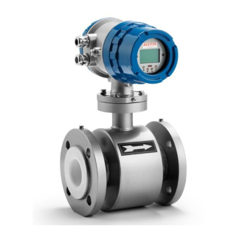
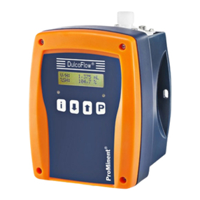
M-series Flow Meter
Manual

____________________________________________________________________________________________________
2
1Contents
1CONTENTS.................................................................................................................................................2
2ABOUT THIS MANUAL...........................................................................................................................4
3PROPRIETARY RIGHTS .........................................................................................................................4
4SAFETY INSTRUCTIONS........................................................................................................................4
5DISTRIBUTORS........................................................................................................................................5
6CUSTOMER SERVICE ..............................................................................................................................5
7ABOUT TROUBLESHOOTING ..............................................................................................................5
8GENERAL INFORMATION .....................................................................................................................5
8.1 GENERAL DESCRIPTION................................................................................................................................... 5
8.2 THE DIFFERENTIAL PRESSURE PRINCIPLE .................................................................................................. 6
8.3 ACCURACY.......................................................................................................................................................... 6
8.4 OVERVIEW.......................................................................................................................................................... 6
8.4.1 Control unit ........................................................................................................................................................ 7
8.4.2 Pipe section......................................................................................................................................................... 7
8.5 PIPE DIMENSIONS............................................................................................................................................. 8
8.6 PED CERTIFICATION........................................................................................................................................ 8
8.7 EMC.................................................................................................................................................................... 9
9INSTALLATION.........................................................................................................................................9
9.1 UNPACKING........................................................................................................................................................ 9
9.2 PREPARATIONS.................................................................................................................................................. 9
9.3 INSTALLING THE FLOW METER....................................................................................................................10
9.4 ELECTRICAL INSTALLATION..........................................................................................................................13
9.5 MODBUS RTU RS485 COMMUNICATION ...................................................................................................13
10 M-DISPLAY (OPTION)....................................................................................................................14
10.1 CHANGING THE DISPLAY SETTINGS..............................................................................................................14
10.2 RST TOTAL .......................................................................................................................................................15
10.3 ROTATE 180....................................................................................................................................................15
10.4 UNIT SELECT....................................................................................................................................................15
10.5 SET QMAX ........................................................................................................................................................16
10.6 RETURN ............................................................................................................................................................16
11 OPTIONAL ACCESSORIES.............................................................................................................. 17
11.1 SEPARATE MOUNTING ...................................................................................................................................17
11.2 SEPARATE MOUNTING –INSTALLATION ....................................................................................................18
11.3 COMBINATION INSTRUMENT,PARALLEL CONNECTOR M ........................................................................19
11.4 COVER IN STAINLESS STEEL..........................................................................................................................20
11.5 SHUT-OFF VALVE CONNECTING BLOCK........................................................................................................20
11.6 COMMUNICATION CABLE FOR FLOW CENTER............................................................................................21
11.7 TOOL KIT FOR ORIFICE EXCHANGE G-BR PIPES.........................................................................................22
12 DIFFERENTIAL PRESSURE MEASUREMENTS......................................................................... 23
12.1 THE DIFFERENTIAL PRESSURE PRINCIPLE ................................................................................................23
12.2 PRESSURE DROP .............................................................................................................................................23
13 THE OUTPUT SIGNAL..................................................................................................................... 25
13.1 CUSTOMIZED RANGE.......................................................................................................................................26
14 MEASUREMENT MODES................................................................................................................26
14.1 DIFFERENTIAL PRESSURE MODE ..................................................................................................................26
14.2 FLOW MODE.....................................................................................................................................................26

____________________________________________________________________________________________________
3
14.3 GAS FLOW MODE .............................................................................................................................................26
15 INSTALLATION MODIFICATIONS............................................................................................... 28
15.1 CHANGE OF FLOW DIRECTION......................................................................................................................28
15.2 CHANGE OF FLOW RANGE .............................................................................................................................28
16 MAINTENANCE................................................................................................................................. 28
16.1 HOUSING...........................................................................................................................................................29
16.2 ELECTRICAL WIRING AND CONNECTIONS....................................................................................................29
16.3 BOLTS AND SCREWS .......................................................................................................................................29
16.4 PROCESS CONNECTION...................................................................................................................................29
16.5 PIPE SECTION ..................................................................................................................................................29
17 TROUBLE SHOOTING .....................................................................................................................29
17.1 INACCURATE FLOW PREDICTION ..................................................................................................................29
17.2 THE METER SHOWS THE WRONG VALUE OR NOTHING AT ALL................................................................30
17.3 LIQUID (OR GAS)IS COMING OUT OF THE CONTROL UNIT .......................................................................30
18 SPARE PARTS.................................................................................................................................... 30
19 TECHNICAL SPECIFICATIONS...................................................................................................... 31
19.1 DIMENSIONS UNIT...........................................................................................................................................31
19.2 DIMENSIONS THREADED PIPE.......................................................................................................................31
19.3 FLANGE FITTED PIPE SECTIONS,CAST IRON /BRONZE METAL WITH SHUT OFF BLOCK ....................32
19.4 FLANGE FITTED PIPE SECTIONS,STAINLESS STEEL ...................................................................................32
19.5 PROPERTY -SPECIFICATION .........................................................................................................................33
20 MEASUREMENT FLOW RANGES, WATER................................................................................36
21 TYPE PLATES.................................................................................................................................... 37
22 BOM...................................................................................................................................................... 38
23 RECYCLING ........................................................................................................................................41

____________________________________________________________________________________________________
4
2About this manual
• This manual relates to the M-series Flow Meter.
• Note that the latest version of this manual is always available as a PDF file on our web site
www.eletta.com.
• On our site you also find other interesting information such as leaflets,
newsletters and application reports.
3Proprietary Rights
This manual contains confidential technical data, including trade secrets and proprietary
information, that are the property of Eletta Flow AB, Sweden.
Any changes or alterations to downloaded or printed Eletta original documentation such as
manuals, drawings, leaflets, newsletters etc, are not permitted without a written permission
from Eletta Flow AB, Sweden.
These data are only disclosed to you under permission of limited use within your company.
Use for manufacturing or processing is not permitted.
Any other use of data and information is strictly prohibited without prior written permission
from Eletta Flow AB, Sweden.
4Safety instructions
In this manual, this warning symbol is used to emphasize where you have to
be particularly careful to avoid injury or damaging the product.
The M-series Flow Meter must not be installed in explosive environments. The
product is not Ex-hazardous approved.
To prevent injury when installing the Flow Meter, make sure that the system is not
pressurized from gas or liquid flow.
There are no serviceable parts inside the instrument. Eletta takes no responsibility for
injury or damage caused by unauthorized disassembly.
Never open the instrument by unscrewing the four hexagon bolts at the top while the
instrument is pressurized.
The electrical installation must only be made by authorized personnel.
Disconnect all power connections before installation or service.
Never exceed the maximum static pressure, which is specified on the product label,
and in this manual.
Make sure that the correct electrical power is used.

____________________________________________________________________________________________________
5
5Distributors
Eletta has appointed a number of distributors all over the world. You will find more
information about your closest distributor at our web site www.eletta.com, or by contacting
our Customer Service Center.
6Customer Service
Our Customer Service Center is available during normal office hours* 8.00 - 16.30 C.E.T., (8
am - 4.30 pm Central European Time).
Phone +46 8 603 07 70 Switchboard
+46 8 603 07 80 Orders and Inquires
Postal Mail Eletta Flow AB
P.O. Box 5084
SE-141 05 Kungens Kurva
SWEDEN
Web www.eletta.com
7About Troubleshooting
Please refer to the trouble-shooting section 17 where we answer the most frequent
questions. We have tried to make this manual as clear and comprehensive as possible, but
we understand that you might run into problems which might not be described in this manual.
In this case your local Distributor or Our Customer Service Center will be more than happy to
answer any of your commercial or technical questions.
8General Information
8.1 General Description
The M-series Eletta Flow Meters are used to measure and control flows of liquids and gases
in threaded pipes with sizes DN15-DN40 and flange fitted pipe sizes DN15 to DN400.
Note that the M-series Flow Meters arrives factory calibrated and programmed at delivery. At
the time of order, data for your specific application is used for configuration of the unit. This
enables quick and easy installation by the user. Only mechanical assembly and electrical
installation are needed. No further adjustments have to be done by the user.
However, it is possible to adjust most parameters in the field after installation using the Eletta
Flow Center or ModBus RTU. You find more information about this in the manual of Eletta
Flow Center.
The viewing settings on optional display version can be changed directly on the meter but will
not effect the meters other settings. For more information, see chapter 10.1.

____________________________________________________________________________________________________
6
8.2 The Differential Pressure Principle
The M-series Eletta Flow Meters are based on the proven and dependable differential
pressure principle and use interchangeable orifice plates for different pipe dimensions and
measuring ranges. See section 12 for more information about the measurement principle.
The M-series Flow Meter is factory calibrated for the differential pressure range of the unit.
The range differs between our three different versions:
•M310, with standard pressure operating range of 5 –500 mbar
•M325, with standard pressure operating range of 12,5 –1250 mbar
•M350, with standard pressure operating range of 25 –2500 mbar
The differential pressure range can be customized using Eletta Flow Center or specified at
the time of ordering.
8.3 Accuracy
The M-series Flow Meter measures media pressure using two independent pressure
transducers. The measurement values are then converted to a flow value by the
microprocessor. The flow accuracy can be separated into:
The M-series pressure sensors have an accuracy of +/- 0,05% F.S.(Full Scale) of the
measured differential pressure.
Our orifices are calculated based on ISO 5167-1:1999/AMD.1:1998. The measurement error
related to the orifice calculation varies because it is is dependent on the type of media, flow
conditions and pipe dimension. At ideal conditions an accuracy within 0,5-1% FS of the
calculated flow can be expected.
Tolerances pipe section and orifice bore diameter contribute to around 0,5-1% FS
Display option:
The 4-20mA signal and ModBus RTU accurasies are unchanges.
The displayed value will not differ from the output during normal use but can differ up to 4.5% during
high power EMC interfearence.
8.4 Overview
M-series is available with four different types of pipes; Threaded G-BR/G-SS and GL, as well
as FA and FSS for flanged fitting. The flow monitor mainly consists of two parts, the Control
Unit and the Pipe Section.
M-BR
M-GL
M-FA
M-FSS

____________________________________________________________________________________________________
7
8.4.1 Control unit
The Control Unit contains the two pressure sensors, the circuit board and the electrical
connector with integrated filter. The circuit board outputs 4-20 mA and ModBus RTU through
the output connector. The settings are adjustable using Flow Center or ModBus. Settings for
the optional display can be changed directly at the meter but will not change the
measurements.
In order to get the unit to work properly with good accuracy, it is very important that the unit is
installed correctly according to the installation instruction, see chapter 9.
8.4.2 Pipe section
The Pipe Section is assembled in-line with the process pipe and the Control Unit is fitted on
top of the Pipe Section. It is also possible, for example when measuring a too hot media, to
install the Control Unit separated (using either steel pipes or tubes) from the Pipe Section.
See section 11.1 Add-Ons, Options.
The Pipe Section contains of an exchangeable Orifice Plate and Plate Holder/Spacers. There
are four different types of pipes; GBR, FA, GL and FSS. (FSS pipe sections contain no
changeable orifice plate - pipe and orifice makes one integrated unit.)
G-BR
-GL
-FA
-FSS

____________________________________________________________________________________________________
8
8.5 Pipe Dimensions
The Pipe Sections are available in various dimensions and materials to fit different
requirements of various applications. Following tables provide a summary of our different
materials and fittings.
Threaded (G)
Pipe material
Type
Available dimensions
De-zincified Brass,
CW602N, EN12420
M-G15BR
DN15 ( ½” BSPP* )
M-G20BR
DN20 ( ¾” BSPP* )
M-G25BR
DN25 ( 1” BSPP* )
M-GL40
DN40 ( 1 ½” BSPP )
DN40 (1 ½” NPT)
Stainless steel
1.4409/EN10213
M-G15SS
DN15 ( ½” BSPP* )
M-G20SS
DN20 ( ¾” BSPP* )
M-G25SS
DN25 ( 1” BSPP* )
* Use NPT adapters for NPT connection (adapters are not included) For GL version NPT
threads are available.
Flange connections
Pipe material
Type
Available dimensions
Powder coated (2022009697096)
steel, 1.0060/E335/SS1650.
FA15 –FA400
DIN DN15 –DN400, PN16
DN15 –DN100, ANSI 150lbs
DN125 - DN200, Suitable ANSI
150 lbs
DN250 –DN300, ANSI 150 lbs
Stainless steel
EN1.4435/EN1.4401/EN1.4404
F15SS-
F400SS
DIN DN15 –DN400, PN16
DN15 –DN400, ANSI 150lbs
Stainless steel SMO254
EN1.4547
F15SS-
F400SS
DIN DN15 –DN400, PN16
DN15 –DN400, ANSI 150 lbs
Bronze
CC491K/493K-GC/GZ/1982
Option
FA15-400
DIN DN15 –DN400, PN16
DN50 –DN100, ANSI 150lbs
DN125 - DN200, Suitable ANSI
150 lbs
DN250 –DN300, ANSI 150 lbs
8.6 PED Certification
M-series complies with applicable parts in Pressure Equipment Directive 2014/68/EU.
Conformity assessment has been performed according to module A. Internal production
control combined with module A2. Internal manufacturing checks with monitoring of the final
assessment, for category 2. Performed by Kiwa Inspecta AB. PED Declaration of conformity
will be sent to you upon request and are also available on www.eletta.com

____________________________________________________________________________________________________
9
8.7 EMC
M-series Flow monitors comply with the EMC directive 2004/108/EC through the following
harmonized standards:
•EN 61 000 –6 –3:2007 Generic Emission –Residential, commercial and light
industry.
•EN 61 000 –6 - 2:2005 Generic Immunity - Industry
M-series Flow monitors with display comply with the EMC directive EN/IEC 61000-6-2:2019
and EN/IEC 61000-6-3:2007+A1 through the following harmonized standards:
•EN/(IEC) 61000-4-2:2009. Immunity to electrostatic discharges.
•EN/(IEC) 61000-4-3:2020. Immunity to radio frequency electromagnetic fields.
•EN/(IEC) 61000-4-4:2012. Immunity to fast transients.
•EN/(IEC) 61000-4-5:2014+A1. Immunity to surge transients.
•EN/(IEC) 61000-4-6:2014. Immunity to conducted radio frequency disturbances.
•CISPR 16-2-3:2016. Measurement of radio frequency electromagnetic field.
9Installation
9.1 Unpacking
Before installation, we kindly ask you to perform the following steps:
1) Check that there are no external damages to the outer packaging. If there are damages,
check if the Flow Meter has been damaged. If there is transportation damage, contact your
forwarder.
2) Check that the delivered parts corresponds to the Packing list. Note that the connection
cable is also included in the package.
The packaging material is made of recycled environmental friendly material, and we kindly
ask you to deal with the material in a way that will have as little impact on the environment as
possible.
9.2 Preparations
Before installation, we kindly ask you to perform the following steps:
1) Eletta recommends that you choose a correct position for the installation of the flow meter
in your pipe system. The following table serves as a guideline.
2) Check that the flow direction in your pipe corresponds to the direction of the Flow Meter.
The flow direction is indicated by an engraved arrow on the Pressure Plate. Note that the
cable connector shall always be located on the upstream side of the pipe section. See
section 15.1 for further details on how to change the flow direction.
Process Media
Correct installation
Liquid
Low level position of the
system.
Gas
High level position of the
system.

____________________________________________________________________________________________________
10
For a GL or FA pipe the engraved arrow on the M-unit should coincide with the red flow
pointer on the pipe, see below pics.
9.3 Installing the Flow Meter
- Disconnect all electrical power before installation!
- Make sure that the system is not pressurized!
1) Install the Flow Meter in any desired direction, vertical or horizontal.
2) If you install the Flow Meter horizontally, make sure that the Control Unit always is
oriented upwards, i.e. on top of the Pipe Section, and not up side down. The reason for this
is to prevent particles in the fluid to collect in the chambers of the pressure sensors. Please
use a filter in the pipeline if your system fluid contains particles.
3) Ensure that you install the Flow Meter according to the correct flow direction, which is
indicated by an engraved arrow. Note that the cable connector shall always be located on the
upstream side.
4) The installation location of the Flow Meter should be rigid and vibration free.
On the rear side of the GBR pipe section there are threaded M6 holes which can be used to
secure the flow meter on a wall or similar using an angle bracket.

____________________________________________________________________________________________________
11
For FA and FSS pipe sections, please support the Flow Monitors with rigid brackets. We
recommend installing them in the pipeline downstream and upstream to avoid unnecessary
stress in the installation area.
If your system still suffers from vibrations, we recommend separate mounting of the Pipe
Section and Control Unit. See section 11.1.
5) It is also of importance that the connecting pipes and flanges are of the same diameter
(inside) and standard as the pipe section. Please refer to section 19. Technical specification
for inside and outside diameters of our different pipes. A mismatch can cause an erratic or
incorrect reading of the flow.
6) Threaded pipes
In the case that the inner diameter of your pipes, including fittings, does not correspond to
the inside diameter of our pipes, inaccuracy may occur. The reason is that such fittings, with
an inside diameter that is too small, will create a media jet stream, which results in a too low
differential pressure, thereby causing measurement error.
If you have to use a tube fitting with too small inner diameter, make sure you locate them
outside of the required straight runs upstream and downstream from the meter.
7) Pipes for flanged fittings
The flanged models, FA and FSS-versions, must be aligned with the counter flanges and
should not be exposed to stress related to unevenly tightened bolts. The flanged models are
delivered with two fiber gaskets and we recommend using these, as they are dimensioned
according to our pipe dimensions. Please ensure that the gaskets are properly aligned and
don’t obstruct the flow.

____________________________________________________________________________________________________
12
d
>15 x d
>5 x d
8) To obtain maximum accuracy, make sure that the system pipe has sufficiently long
straight run before the Flow Meter (upstream). We recommend that the straight run
corresponds to at least 15 times the present inner diameter of the pipe.
Also make sure that the run after the Flow Meter (downstream) is at least 5 times the inner
diameter of the pipe.
Also make sure that there are no valves, bends or diameter changes. This to avoid flow
disturbances which might cause inaccurate reading of the flow.
Note
In applications where maximum accuracy is not necessary, the lengths of the runs can be
reduced. Note that it is practically impossible to predict where and when a flow gets
stable after a disturbance. Therefore, the recommendation above serves only as a
guideline, i.e. a method that has proven to secure the measurement accuracy. If shorter
runs are used, Eletta neither can guarantee the specified maximum accuracy, nor predict
the flow in your specific application.

____________________________________________________________________________________________________
13
Max. 1 300 meters
Max. 14 meters
Device1 Device2 Device3 Master Device4 Devicen
buslink
9.4 Electrical Installation
The electrical installation must only be made by authorized
personnel!
Do not install the M-series flow meter in Ex-hazardous areas!
The connection cable is included in the purchase of your M-unit. The cable has eight wires
and a M12-female connector with screw locking and one end open. The Standard cable
length is 2,5 m. A 10 meter cable is available as an option.
In the case you want to splice the cable in order to extend the cable further than 10 meters,
please make sure that the conductive area of the wires for the output signal is at least 0,25
mm2(0,00039 inch2). Maximum output load is 1 kΩ.
Make sure that you use the correct power supply, the allowed voltage range is between +8 to
+28 VDC.
A wiring diagram is attached on the cable from factory.
Below is the wiring connection for the M12 M3XX unit. The configuration is referenced
looking at the female of the cable connecting to M unit.
9.5 Modbus RTU RS485 communication
The physical connection is provided by the RS485 serial interface. This guarantees good
interference immunity and enables a flexible bus structure, i.e. several devices can be
administrated as slaves by a single master. In order to minimise the scope of cabling, the
RS485 is used in half-duplex mode. This means that 2 wires are required for
communications and 2 wires for power and ground.

____________________________________________________________________________________________________
14
In order to operate several devices at one serial interface, they are simply all connected in
parallel (RS485A, RS485B, GND and +Vcc). Before incorporating the devices into the bus,
each device must be programmed with a different address. It is possible to configure a
network up to a length of 1300 metres with a maximum of 128 devices. Each riser cable may
be up to 14 m in length. The employed cable should correspond to specification EIA RS485.
The Modbus RS485 Comunication protocol is too extensive to describe in this manual. The
M-series ModBus manual contains further information regarding the communication.
10 M-Display (option)
Loop powered display of OLED 128*32 Pixels to show flow rate, flow total and 4-20 mA
analog output value.
The M-series with display has three display modes that are cycled by pressing the green
center button. The up and down arrows are exclusively for changing settings of the meter
and are not needed during normal operation.
The totalized view displays the total amount of liquid that has
passed the unit and
display is in the user
select unit
(liters, gallons etc).
10.1 Changing the display settings
The M-series settings are independent from the values sent through ModBus RTU and Flow
Center.
Press the up and down arrow down simultaneously for 5 seconds until the display changes to
display "Rst total", this indicates that the meter is in "settings mode".
The meter has five menu entries;
•Rst Total
•Rotate 180
•Unit Select
•Set Qmax
•Return.
The menu entries are cycled by pressing the up or down arrow and selected by pressing the
green button.
Figure 2: 4-20mA
Figure 1: Flow unit
Figure 1: Totalization

____________________________________________________________________________________________________
15
10.2 Rst total
Pressing the green button will reset the volume of the logged flow to zero.
10.3 Rotate 180
Pressing the green button will rotate the screen 180 degrees/ flip it horizontally; the buttons
will be automatically adjusted for the viewing angle.
10.4 Unit select
Pressing the green button will bring up the unit submenu. You are able to cycle through the
different unit options by pressing up or down arrow and selecting the wanted unit by pressing
the green button.
The possible unit of measurement to choose are: LPM, CMH, LPS, CFM, CFH and %.
Other units may be possible to make available on request.

____________________________________________________________________________________________________
16
10.5 Set Qmax
The Set Qmax menu is used to set the maximum flow value witch is the same maximum
value set in flow center. Each number is increased by pressing the up arrow and decreased
by pressing the down arrow, pressing the green button will select the shown value. The
chosen number will shift to the left by one for each press of the green button. Leave a value
blank or at zero if you do not require such high numbers. This is only used when recalibrating
the display.
10.6 Return
Pressing the green button in the Return menu will bring you back to the main menu showing
the current flow.

____________________________________________________________________________________________________
17
11 Optional accessories
11.1 Separate Mounting
Sometimes, the pipe Section and the Control Unit need to be separately located from each
other. The reasons could be lack of space, high system media temperature or vibrations. The
following section explains our Separate Mounting kit.
The orifice plate creates two pressures, one on each side of the plate. These pressures are
distributed to the two pressure sensors in the Control Unit through channels in the pressure
plate and the pipe section. When installing the Pipe Section and the Control Unit separately,
these channels are extended by using two plastic hoses. These hoses are fitted between the
Pipe section and the Control Unit using two adapters.
As a standard, two 1,75 m (5.74 feet) PA plastic hoses are delivered with the Separate
mounting kit. The diameter is 6 mm (0,23 inch) and suitable for a maximum temperature of
90 °C (194 °F) and a maximum pressure of 10 bar (145 PSI).
The plastic hoses shall not be used for temperatures higher than 90 °C (194 °F) or
pressures higher than 10 bar (145 PSI). If your process temperature or pressure exceeds
these levels, we recommend you to use copper or stainless steel pipes. Such pipes are not
included with the product. Choose material with respect to the type of liquid or gas in your
system. If you are using a chemical reactive media, check with your tubing supplier which is
the most suitable material to use for your application.
For a separate mounting you need two different adapters. One that is installed on the Pipe
Section and one for the Control Unit.

____________________________________________________________________________________________________
18
The Control Unit Adapter has valves for discharging entrapped air. There is also an angle
bracket included for wall fitting.
We recommend installing the Pipe Section and the Control Unit as close to each other as
practically possible. This will facilitate future trouble-shooting and on-site calibration.
The plastic hoses can be replaced by 6 mm metal pipes (for instance copper or stainless
steel) depending of the system media, pressure and temperature. Such pipes are not
supplied by Eletta Flow, contact a local hardware store or plumber. If you are using a
chemical reactive media, check with your tubing supplier which is the most suitable material
to use for your application.
11.2 Separate Mounting –Installation
1) Install the Pipe Section according to the instruction in chapter 9. In this case you can
mount the Pipe Section in any direction, vertically or horizontally, and with the pressure
channels pointing upwards, downwards or sideways.
2) Assemble the Pipe Section Adapter to the Pipe Section. (If separate mounting is ordered
together with control unit and pipe section the adapter is assembled from factory.)
3) Find a suitable place for installing the Control Unit. We recommend that the Control Unit is
installed where it is easily accessed with respect to maintenance.
4) Assemble the Control Unit Adapter to the Control Unit. (If separate mounting is ordered
together with control unit and pipe section the adapter is assembled from factory.)
5) Install the Control Unit Adapter to a wall, a pipe or other rigid object.

____________________________________________________________________________________________________
19
6) Ensure that the hoses have the same length in order to avoid different pressures between
the two channels, which will cause inaccurate flow reading.
7) Both adapters have engraved “+” and “– “signs. Connect one of the hoses between the
respective “+” signs. The “+” sign represents the upstream side. Tighten with care.
Connect the other hose between the respective “-“ signs. The “-“ sign represents the
downstream side. Tighten with care.
11.3 Combination instrument, Parallel connector M
With a parallel connector it is possible to connect a M-flow meter together with a V or S-
series flow monitor on the same pipe section (GL, FA and F-SS type). This makes it possible
to combine the reliable and capable switch functionality of the S and V-series with an analog
mA-signal.
S- and M- series on
F-SS pipe section
V- and M- series on
FA pipe section

____________________________________________________________________________________________________
20
S and V-series works with pressures up to 16 bar (g). All three versions of our M-units can be
used with the parallel connector but as a guideline we recommend that:
- M310 is used for static pressures up to 10 bar(g).
- M325 is used for static pressures between 10 bar(g) to 25 bar(g)
- M350 used in applications where there are risks for water hammer pulses which could
damage pressure transmitters of lower pressure ranges.
If you purchase a complete parallel unit; M-unit with S or V-series; it will arrive assembled
into one unit from factory. For installation instructions of the pipe section, reference to section
9.3. For electrical installation of the M-unit refer to section 9.4 in this manual. For electrical
installation instructions of the combination flow monitor, reference to the individual manual of
that flow monitor (normally V- or S-series).
It is possible to upgrade an existing V or S-series flow monitor with a Parallel connector.
When ordering the parallel connector and M-unit it is necessary to state which type of flow
monitor the M-unit will be working together with; normally a V1, S2, V15 or S25 unit. The M-
series will then be configured accordingly from factory. It is also possible to re-configure your
M-unit with our configuration software Eletta Flow Center.
11.4 Cover in Stainless steel
The cover of the M-unit is manufactured in Polyamid plastic; PA12 (Grillamid 1kn-5h). It is
known to be chemical resistant to most common fluids for which the M-series is used. But in
rare cases with even tougher environments M-series is also available with a Stainless steel
cover as an option. Our stainless steel cover is made in EN 1.4436 (grade 316).
11.5 Shut-off valve connecting block
The shut off block is only available for FA and GL15-40 pipe sections.
The shut off block is based upon a reliable solution. The shut off block closes the pressure
channels between the control unit and the pipe section and allows disassembly of the control
unit while the system is pressurized.
If there are no shut off valves in the system and there is maintenance on a regular basis
(check or clean the pressure channels, inspection of orifice, calibrations etc.). Then it is a
good idea to order the M-unit with a shut off block. With a shut off block you’ll not require a
separate shut off valve system and you don’t need to de-pressurize the whole system.
There are two flow selectors, see below picture, when a shut off block is installed. Factory
default will always be that both flow selectors are orientated in either –L- (Right to left flow) or
–R- (Left to Right flow) according to the order information provided by the customer. But for
This manual suits for next models
3
Table of contents
Other Eletta Measuring Instrument manuals
