Elettrotest CPS/T Series User manual


28/01/22 User Manual CPS/T 5-40k 62000585_03_ 2
CPS/T Models covered in this manual:
Model
Code
CPS/T 5kVA
99110770
CPS/T 10kVA
99110780
CPS/T 20kVA
99110790
CPS/T 40kVA
99110800
This manual is written from CPS/T firmware version CPSX 010_.
Please check the latest manual version at www.elettrotestspa.it
To consult older manual versions, please contact our support at

28/01/22 User Manual CPS/T 5-40k 62000585_03_ 3
Document list:
This manual is completed by a list of documents, useful to understand all the features of your
CPS/T.
Scan the QR-code or click on the link to directly download the documents.
Documents
Description
Link
QR-code
User Manual
Latest manual version
Manual
Brochure
Brochure for all the TPS-HPS-CPS models
Brochure
CPS Parameters
Describes all the machine modifiable
parameters and the start-up sequence.
CPS
Parameters
CPS protocol
Elettrotest
Describes how the Elettrotest remote
communication protocol works.
Elettrotest
Protocol
CPS protocol
SCPI
Describes how the SCPI remote
communication protocol works with your
CPS/T.
SCPI
Protocol


28/01/22 User Manual CPS/T 5-40k 62000585_03_ 5
Elettrotest Spa
P,zza R.Riello 20/B
45021 Badia Polesine (RO)
Italy
+39 042553567
www.elettrotestspa.it
After sale support
Thank you for purchasing the CPS/T generator.
CPS/T is a three-phase generator that provides a perfectly sinusoidal and stable voltage. The
voltage value can be adjustable either in frequency and amplitude.
CPS/T combines the advantage of the power line, the variac and the rotary converter, without
having their shortcomings.
Responsability:
Elettrotest disclaims any responsibility for damage to people or things
caused by an improper use of its products.
Mandatory
-Verify voltage, power and frequency compatibility between CPS/T range and electrical
specification of equipment under test (EUT).
-Electrical components of the system must be suitable for the rated voltage and current of CPS/T
model
-The electrical components, which by construction cannot support external influences (of the
generator in all its range), can only be used on condition that adequate additional protection has
been provided with automatic disconnection protection.
Notes:
This manual lists precautions and information about operating procedure of device.
The content of this manual is subject to change without prior notice because of continuing
improvements on the instrument’s
Should you have any questions or find any error please contact us by email.
Copying or reproducing all or any part of the contents of this document is strictly
prohibited, without Elettrotest permission
Version:
This manual is written for CPS/M firmware version CPSX 010_ and higher.

28/01/22 User Manual CPS/T 5-40k 62000585_03_ 6
SAFETY WARNINGS
The manufacturer urges users to read the user manual for our products before installation.
The installation must be carried out by qualified technical staff. The non-observance of the
warnings in this manual can cause electric shocks, even fatal ones.
Please find some general safety warnings below.
•This equipment must be connected to the mains supply using the appropriate safety
devices.
•CPS/T must be connected to safety ground through the correct connections. The non-
observance or the degradation of this earth connection can lead to electric shocks, even
fatal ones. As regards the correct connection modes, please refer to the information
contained in paragraph 4.
•Disconnect CPS/T from the mains before any work on the equipment and on the connected
power loads.
•Before touching the load or the output connector make sure that the power supply on the
device has been disconnected for at least 5 minutes. This is the time necessary in order for
the capacitors inside the device to discharge. The non-observance of this discharge time
can lead to electric shocks, even fatal ones.
•Avoid heavy shocks to the equipment (especially during transport) or exposure to extreme
weather conditions.
•Any damage to the product due to transportation, incorrect installation or improper use is
not covered by the guarantee supplied by the manufacturer.
•Do not use the equipment in explosive environments or in the presence of dust, acids or
corrosive and/or inflammable gases.
•Tampering with or dismantling any component in the equipment will void the warranty
automatically.
•Do not operate or store under conditions where condensing may occur or where
conductive debris may enter in the case.
•Keep the ventilation holes on the front and rear free from obstruction.
•Do not make dielectric strengths test on the input or output of the equipment. Contact
Elettrotest if you need to do specific test
ELECTRIC RISK
There are dangerous voltages inside CPS/T and over the output connector.
The non-observance of the warnings suggest in this manual can lead to electric
shocks, even fatal ones.
OVERHEATING RISK
In the case of a ventilation system failure, the metal parts of the inverter may reach
high temperatures (in some cases higher than 70°C).

28/01/22 User Manual CPS/T 5-40k 62000585_03_ 7
DISPOSAL
INFORMATION FOR USERS ON THE CORRECT HANDLING OF WASTE
ELECTRICAL AND ELECTRONIC EQUIPMENT (WEEE)
In reference to European Union directive 2012/19/EU issued on 24 July 2012 and the related
national legislation, please note that:
•WEEE cannot be disposed of as municipal waste and such waste must be collected and
disposed of separately;
•the public or private waste collection systems defined by local legislation must be used. In
addition, the equipment can be returned to the manufacturer at the end of its working life
when buying new equipment;
•the equipment may contain hazardous substances: the improper use or incorrect disposal
of such may have negative effects on human health and on the environment;
•the symbol (crossed-out wheeled bin) shown on the product or on the packaging and in the
instruction sheet, indicates that the equipment must be disposed of separately;
•in the event of illegal disposal of electrical and electronic waste, the penalties are specified
by local waste disposal legislation.

28/01/22 User Manual CPS/T 5-40k 62000585_03_ 8
INDEX
1. INTRODUCTION..........................................................................................................................10
1.1 MAIN FEATURES ..................................................................................................................10
1.1.1 Output voltage .............................................................................................................10
1.1.2 Output frequency.........................................................................................................11
1.1.3 User interface...............................................................................................................11
2. MODELS......................................................................................................................................12
2.1 TECHNICAL SPECIFICATIONS ...............................................................................................13
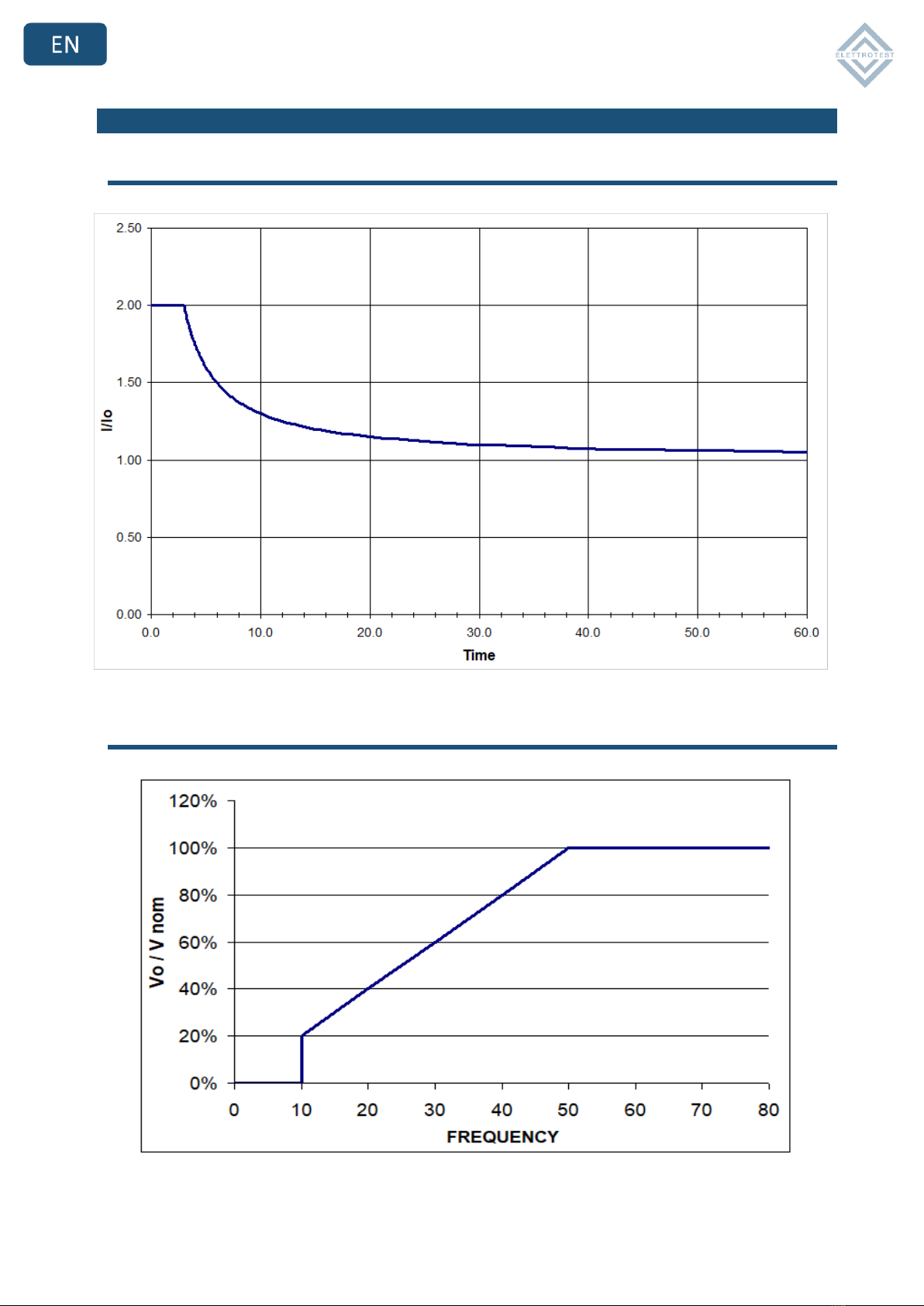
2.1.1 IN RUSH CURRENT LIMIT..............................................................................................13
2.1.2 V/f RATIO......................................................................................................................13
2.2 MECHANICAL DRAWINGS....................................................................................................14
2.2.1 CPS/T 5K 4K8S ..............................................................................................................14
2.2.2 CPS/T 10K 8K16S ..........................................................................................................15
2.2.3 CPS/T 20K 15K30S & CPS/T 40K 30K60S......................................................................16
3. NOTES FOR USERS......................................................................................................................17
3.1 SWITCHING ON....................................................................................................................17
3.2 PARAMETERS PROGRAMMING MODE................................................................................17
3.3 VOLTAGE MENU ..................................................................................................................17
3.4 RANGE SETTINGS.................................................................................................................18
3.5 CURRENT AND VOLTAGE VISUALIZIATION..........................................................................18
3.6 FREQUENCY MENU..............................................................................................................19
3.6.1 Frequency setting.........................................................................................................19
3.6.2 Frequency reference setting........................................................................................19
3.7 CONTINUOUS AND INRUSH MODE .....................................................................................20
3.8 MODE MENU.......................................................................................................................20
3.8.1 Voltage reaction...........................................................................................................20
3.8.2 Output type..................................................................................................................21
3.8.3 Output relay.................................................................................................................21
3.9 ALARMS MENU....................................................................................................................21
3.9.1 Supply alarms...............................................................................................................22
3.9.2 System alarms..............................................................................................................22
3.9.3 Current alarm...............................................................................................................22
3.9.4 Voltage alarm...............................................................................................................22
4. INSTALLATION............................................................................................................................23
4.1 GENERAL NOTES..................................................................................................................23
4.1.1 INSPECTION..................................................................................................................23
4.2 INSTALLATION NOTES..........................................................................................................23
4.2.1 CPS/T 5K 4K8S ..............................................................................................................23
4.2.2 CPS/T 10K 8K16S | CPS/T 20K 15K30S | CPS/T 40K 30K60S........................................25
4.3 PROTECTIONS......................................................................................................................27
4.3.1 CPS/T WIRING ..............................................................................................................27
4.3.2 RCD PROTECTION.........................................................................................................27
4.3.3 MAGNETO-THERMAL PROTECTION.............................................................................28
4.3.4 ACCESSORIES................................................................................................................28

28/01/22 User Manual CPS/T 5-40k 62000585_03_ 9
4.4 WIRING DIAGRAM...............................................................................................................29
4.4.1 2 WIRE CONFIGURATION .............................................................................................29
4.4.2 4 WIRE CONFIGURATION .............................................................................................30
5. REMOTE CONTROL.....................................................................................................................31
5.1 Control software..................................................................................................................31
5.1.1 RS232 serial cable ........................................................................................................31
5.2 EXISTENCE TABLE.................................................................................................................32
6. SERVICE AND MAINTENANCE ....................................................................................................33
6.1 MAINTENANCE / CLEANING................................................................................................33
6.1.1 Scheduled maintenance...............................................................................................33
6.2 ALARMS DIAGNOSIS AND REPAIRS .....................................................................................33
6.3 BASIC TROUBLESHOOTING..................................................................................................34
6.3.1 Overvoltage/Undervoltage alarms ..............................................................................34
6.3.2 Overtemperature alarm...............................................................................................34
6.3.3 Inverter alarm ..............................................................................................................35
6.3.4 Max DV OUT alarm.......................................................................................................35
6.3.5 Limit IOUT alarm ..........................................................................................................36
7. GUARANTEE ...............................................................................................................................37
8. INDEX REVISION .........................................................................................................................37

28/01/22 User Manual CPS/T 5-40k 62000585_03_ 10
1. INTRODUCTION
CPS/T is a power source that supplies sinusoidal stable voltage. Its output voltage is adjustable in
frequency and amplitude.
CPS/T can also be controlled remotely.
1.1 MAIN FEATURES
1.1.1 Output voltage
The output voltage is guaranteed perfectly sinusoidal, with a distortion less than 0.6 % regardless
of the load. The output voltage value is kept perfectly stable within 0.1 % regardless of the load.
CPS/T is also able to compensate for possible voltage drops on the output wires, ensuring in this
way the exact voltage you want on the load.
The load that CPS/T is able to drive can vary from the pure capacity to the pure inductance not
only, but also up to non-symmetrical current loads, as for instance a single halfwave rectifier.
The output voltage is adjustable with continuity from zero to full scale of each range.
CPS/T can in fact provide the nominal power at various full scales and this allows the CPS/T to
adapt himself to the disparate needs of the user, without having heavy limitations on the output
current.
Furthermore, CPS/T is capable to keep the voltage stable also with time-dependent loads, as for
example the pulsating loads. Indeed, CPS/T recovers the distortion of the waveform within 0.6 %
and the amplitude of the voltage within 0.1% in less than half period.
Furthermore, CPS/T can bear a short-circuit for an indefinite time without suffering any
consequence
INVERTER
AND
FILTER
L1
NEUTRAL
L2
L3
L1
NEUTRAL
L2
L3

28/01/22 User Manual CPS/T 5-40k 62000585_03_ 11
1.1.2 Output frequency
CPS/T allows the regulation of the output frequency from 50Hz or 60Hz by panel and 10-80Hz by
remote control.
This output frequency can be regulated with continuity within the above frequency’s range and it
has a stability of 0.01% with regards to the set frequency.
CPS/T also allows to synchronize the output frequency with the frequency of the supply line (from
remote control). This allows a completely synchronous voltage output, with a far superior voltage
stability.
It must be remarked that, through remote interface, it is possible to set a variable phase delay on
all the three outputs.
The resolution of phase setting is 0,088° (12 bits on 360°).
1.1.3 User interface
CPS/T is designed to have a user-friendly interface.
It is also featured the possibility of a host computer control, thus allowing to perform tests
automatically.
CPS/T allows various usage selections: working range, wires drop compensation, working
frequency,
synchronization of the output frequency with the power line.
Furthermore, CPS/T gives the user clear information on the status of the output.
It is monitored both the set voltage, the set frequency and the output voltage and current is read
with a precision of 0.3%.
The user is also warned in case of overcurrent obtainable by the CPS/T, or in case of high loss in
the wires. this should not exceed 5% of the set voltage.
We underline again that CPS/T automatically limits the maximum allowed current, avoiding
damages to the equipment.
When it occurs, the precision of the output waveform and the accuracy of the output voltage are
not guaranteed.
The user can set the output voltage through the knob, for the frequency you can choose
50Hz/60Hz.

28/01/22 User Manual CPS/T 5-40k 62000585_03_ 12
2. MODELS
The following tables show all the characteristics of all CPS/T models:
CPS5KVA
CPS10KVA
CPS20KVA
CPS40KVA
Code
99110770
99110780
99110790
99110800
Configuration
Continuous
Inrush
Continuous
Inrush
Continuous
Inrush
Continuous
Inrush
Power
5KVA
4KVA/8KVA
10KVA
7.5KVA/15KVA
20KVA
15KVA/30KVA
40KVA
30KVA/60KVA
Output
1phase / 3phase
1phase / 3phase
1phase / 3phase
1phase / 3phase
Characteristic
Not Isolated
Not Isolated
Not Isolated
Not Isolated
Voltage
Range
150V/300V1)
150V/300V1)
150V/300V1)
150V/300V1)
Accuracy
<0.5%
<0.5%
<0.5%
<0.5%
Distortion
<0.6%(2)
<0.6%(2)
<0.6%(2)
<0.6%(2)
Stability of the output voltage
<0.1%
<0.1%
<0.1%
<0.1%
Recovery time of the waveform
<10ms
<10ms
<10ms
<10ms
Maximum Compensated drop
5% f.s
5% f.s
5% f.s
5% f.s
Recovery-time of drop on wires
<200ms.
<200ms.
<200ms.
<200ms.
Output voltage resolution
0.025% f.s.
0.025% f.s.
0.025% f.s.
0.025% f.s.
Maximum current single phase
Configuration
Continuous
Inrush
Continuous
Inrush
Continuous
Inrush
Continuous
Inrush
Range
150V
300V
150V
300V
150V
300V
150V
300V
150V
300V
150V
300V
150V
300V
150V
300V
RMS continuous 2)
33.2A
16.6A
26.7A
13.3A
66.4A
33.2A
50A
25A
133A
66.4A
100A
50A
266A
133A
200A
100A
Inrush Current (3 seconds)2)
No inrush
53.4A
26.6A
No inrush
100A
50A
No inrush
200A
100A
No inrush
400A
200A
Maximum current three phase
Configuration
Continuous
Inrush
Continuous
Inrush
Continuous
Inrush
Continuous
Inrush
Range
150V
300V
150V
300V
150V
300V
150V
300V
150V
300V
150V
300V
150V
300V
150V
300V
RMS continuous (2)
11.1A
5.5A
8.9A
4.4A
22.2A
11.1A
16.7A
8.3A
44.4A
22A
33.4A
16.7A
88.9A
44A
66.8A
33.4A
Inrush Current (3 seconds)2)
No inrush
17.8A
8.8A
No inrush
33.4A
16.6A
No inrush
66.8A
33.4A
No inrush
134A
66.8A
Frequency
Output frequency range
50Hz(3) - 80Hz
50Hz(3) - 80Hz
50Hz(3) - 80Hz
50Hz(3) - 80Hz
Range of synchronization
45Hz - 65Hz
45Hz - 65Hz
45Hz - 65Hz
45Hz - 65Hz
Frequency resolution
0.02Hz
0.02Hz
0.02Hz
0.02Hz
Frequency precision
100ppm
100ppm
100ppm
100ppm
Supply
Input supply
400Vac ± 10% 3PH+N
400Vac ± 10% 3PH+N
400Vac ± 10% 3PH+N
400Vac ± 10% 3PH+N
Maximum Input current
12A/24A neutral
23A/23A neutral
42A/42A neutral
85A/85A neutral
Input Frequency
50Hz-60Hz
50Hz-60Hz
50Hz-60Hz
50Hz-60Hz
Other
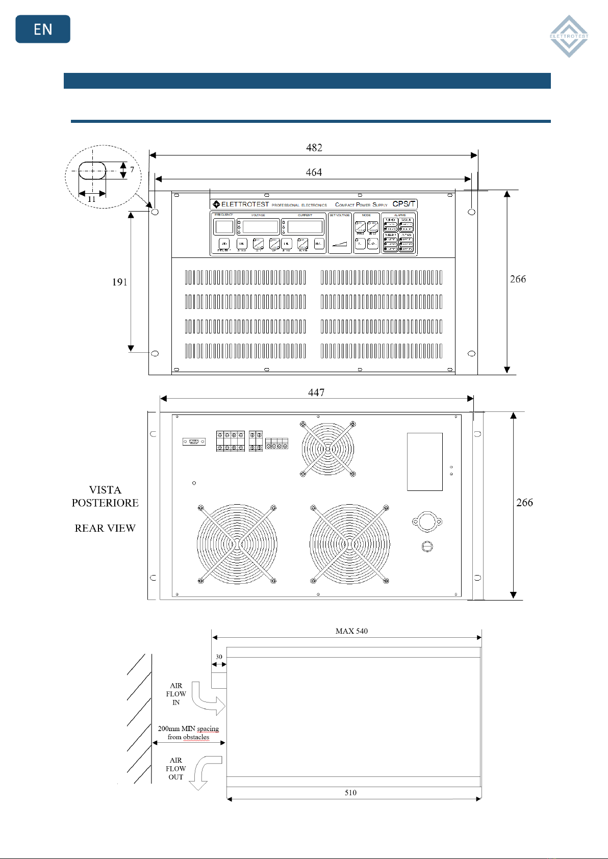
Size (H : W : D)(mm)
281 : 471 : 513
1150 :585 : 600
1410 :585 : 600
1410 :585 : 600
Weight
54Kg
180Kg
300Kg
450Kg
Protections
OVP;UVP;OTP
OVP;UVP;OTP
OVP;UVP;OTP
OVP;UVP;OTP
Operation Temperature Range
0-35°C
0-35°C
0-35°C
0-35°C
RS232
YES
YES
YES
YES
RS485
OPTION
OPTION
OPTION
OPTION
LAN
OPTION
OPTION
OPTION
OPTION
28/01/22 User Manual CPS/T 5-40k 62000585_03_ 13
2.1 TECHNICAL SPECIFICATIONS
2.1.1 IN RUSH CURRENT LIMIT
2.1.2 V/f RATIO
28/01/22 User Manual CPS/T 5-40k 62000585_03_ 14
2.2 MECHANICAL DRAWINGS
2.2.1 CPS/T 5K 4K8S

28/01/22 User Manual CPS/T 5-40k 62000585_03_ 15
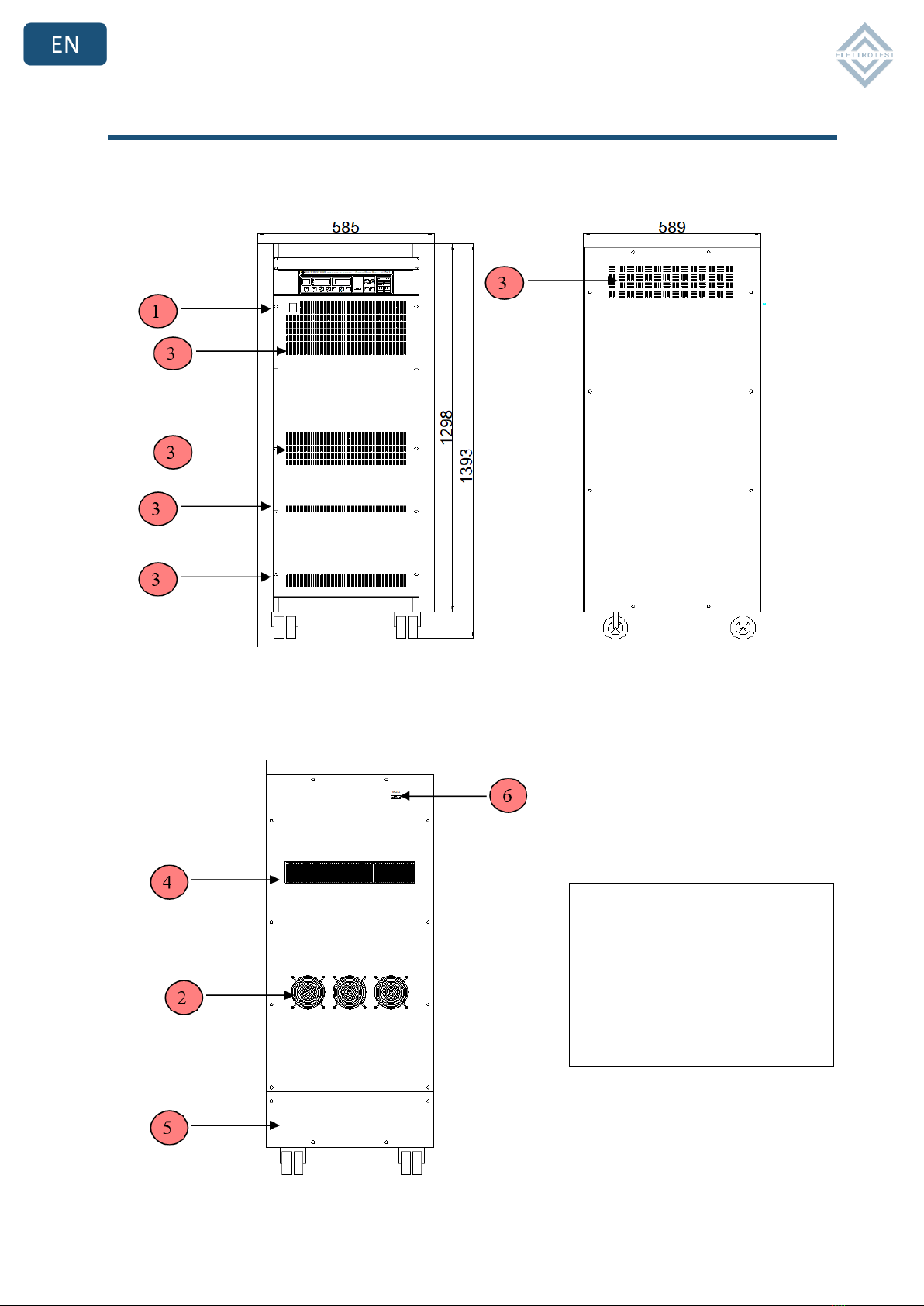
2.2.2 CPS/T 10K 8K16S
All measures are in mm.
1 –On/Off Switch
2 –Output Fans
3 –Grill for input air flow
4 –Grill for output air flow
5 –Rear panel
6 –Serial RS232 DB9 connector
28/01/22 User Manual CPS/T 5-40k 62000585_03_ 16
2.2.3 CPS/T 20K 15K30S & CPS/T 40K 30K60S
All measures are in mm.
1 –On/Off Switch
2 –Output Fans
3 –Grill for input air flow
4 –Grill for output air flow
5 –Rear panel
6 –Serial RS232 DB9 connector

28/01/22 User Manual CPS/T 5-40k 62000585_03_ 17
3. NOTES FOR USERS
3.1 SWITCHING ON
As soon as CPS/T switches on, through the switch placed on the control panel of the machine, it
makes different cycles of test, indicated by the progression of the numbers from 0 to 9 on the
displays.
In case of bad working the test stops and the machine indicates on the control panel the type of
alarm checked (see at the voice alarms).
Caution: The front switch is not a security switch, it opens only the three phase power line also
the neutral is connected. High dangerous voltage remains inside the machine.
3.2 PARAMETERS PROGRAMMING MODE
CPS / T allows you to change various generator start parameters through the programming mode.
The programming mode allows you to configure a starting profile of the application, different from
the factory one.
The modifiable parameters and how to access the programming mode are illustrated in the
Configure parameters quick guide.
3.3 VOLTAGE MENU
To set the output voltage you must use the encoder that you see on the figure, after this step the
set of voltage the display lamp until the output is going to the voltage set up.

28/01/22 User Manual CPS/T 5-40k 62000585_03_ 18
3.4 RANGE SETTINGS
The ranges button allows to make use of the full power output at different voltages, 150V (Low)
or 300V (High).
The maximum output power changes according to the nature of the connected load; in case of
resistance loads the power is nominal, in case of pure inductive loads the power increases, in
case of pure capacity load the power decreases. To change the range, push the button RANGE
highlighted in the figure.
When the range is changed, the voltage display turns off and the output voltage goes down slowly
till zero, then the output power is switched off; after about 15 seconds the output is switched on
again and the voltage display visualizes zero voltage (0.0); since that moment CPS/T is ready to
receive commands on the new range
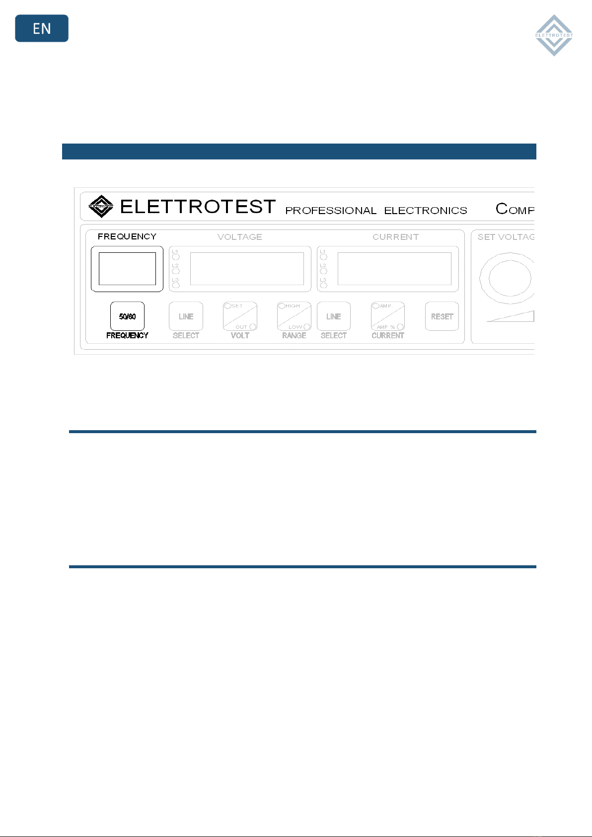
3.5 CURRENT AND VOLTAGE VISUALIZIATION
When CPS/T is turned on for the first time, the display visualizes the set voltage. In order to
visualize the actual output voltage, push VOLT button and the SELECT button to choose the line.
The displayed voltage value has a precision of 0.3% full scale range. If the set voltage is changed,
the display returns to show the set value. In case of 4 wires operation, the display shows the
voltage on the sense inputs.
You can see the output current on CURRENT display.
28/01/22 User Manual CPS/T 5-40k 62000585_03_ 19
There are two different selection buttons, the one below the voltage display changes the
displayed line for the voltage and the one below the current display changes the displayed line for
the current.
Both current and voltage displays show four digits
3.6 FREQUENCY MENU
3.6.1 Frequency setting
The output frequency of CPS/T can be set at 50Hz or 60Hz, the FREQUENCY display shows the set
up value and FREQUENCY button switch the set up value.
In this case too after pushing the button FREQUENCY the frequency display flashes until the
output frequency coincides with the set one.
3.6.2 Frequency reference setting
The output frequency can have two different references: the first one is an inner frequency
reference with a precision of 0.01%, the second one is the line of loading frequency.
At turn on CPS/T is connected to the inner reference; you can change the reference to line only
with PC remote interface.

28/01/22 User Manual CPS/T 5-40k 62000585_03_ 20
3.7 CONTINUOUS AND INRUSH MODE
Through the current key you can select the Continuous (Amp) or inrush (Amp%) configurations, it
changes the limit of peak and RMS current. The change is available of until the machine is running
3.8 MODE MENU
3.8.1 Voltage reaction
The output voltage’s stabilization behaves in the same way in both the CPS/T output terminals (2
WIRE) and on a possible long-distance outlet (4 WIRE), to eliminate the fall in voltage due to cable
connections.
To operate the long-distance stabilization, first connect the opposite terminals on the back of the
machine following the indications at the voice INSTALLATION.
The output voltage’s stabilization can be chosen by pushing the buttons SENSE, the 4WIRE and
2WIRE configuration is indicated with a LED.
This manual suits for next models
4
Table of contents
Languages:
Other Elettrotest Power Supply manuals


Popular Power Supply manuals by other brands

Berker
Berker 7591 00 03 manual

TDK-Lambda
TDK-Lambda Genesys Series user manual

Amrel
Amrel PPS-1326 manual

Deif
Deif DPS-1 Installation and operation instructions

Matsusada Precision
Matsusada Precision R4G Series instruction manual

Keysight Technologies
Keysight Technologies N69100 Series Operating and service guide


Bluetti
Bluetti AC60P user manual

Simco-Ion
Simco-Ion IQ Power HL Installation and operating instructions

Pulsar
Pulsar PSCL12020 quick start guide

Ametek
Ametek Sorensen DCS8-350E Operation manual

Pentair
Pentair HYDROMATIC A+ Installation and service manual

Circuit Specialists
Circuit Specialists CSI3303S user manual