Simco-Ion IQ Power HL User manual

5201258 Rev. C
IQ Power HL Power Supply
IQ Power™ HL Power Supply
with Sensor Technology
Associated Equipment - Appareillage Connexe
for the IQ Power HL Static Bar
INSTALLATION AND OPERATING INSTRUCTIONS

i
IQ Power HL Power Supply 5201258 Rev. C
TABLE OF CONTENTS
1. SAFETY WARNINGS.................................................................................................1
2. DESCRIPTION ..........................................................................................................3
Features ...................................................................................................................4
3. SPECIFICATIONS .....................................................................................................4
4. INSTALLATION.........................................................................................................5
Mounting................................................................................................................5
Electrical Connections.............................................................................................6
Power Supply Number (Address / Device Number) ..............................................15
Set Up (with IQ Power Control Station) ..............................................................15
5. OPERATION .......................................................................................................... 19
Power Supply Indicators........................................................................................19
Power Supply Operators........................................................................................19
System Start-up.....................................................................................................20
System Operation (with IQ Power Control Station) ............................................21
6. MAINTENANCE..................................................................................................... 22
Cleaning the Static Bar..........................................................................................22
7. TROUBLESHOOTING ............................................................................................ 23
8. PARTS & ACCESSORIES ........................................................................................ 25
9. WARRANTY & SERVICE ........................................................................................ 26

1
IQ Power HL Power Supply 5201258 Rev. C
1. SAFETY WARNINGS
Simco-Ion recommends that these instructions be read completely before installation
or operation is attempted. Failure to do so could result in personal injury and/or
damage to the equipment.
NOTE – Statements identified with NOTE indicate precautions necessary
to avoid potential equipment failure.
CAUTION – Statements identified with CAUTION indicate potential
safety hazards.
ATTENTION – Les déclarations identifiées avec ATTENTION indiquent
des dangers potentiels pour la sécurité.
WARNING – Statements identified with WARNING indicate potential
serious injury hazards.
AVERTISSEMENT – Les déclarations identifiées avec AVERTISSEMENT
indiquent un risque de blessures graves.
NOTE – This equipment must be correctly installed and properly
maintained. Adhere to the following notes for safe installation and operation:
1. Read instruction manual before installing or operating equipment.
2. Only qualified service personnel are to perform installation and repairs.
3. All equipment must be properly grounded, including machine frame to which
the equipment is mounted.
4. Disconnect input power before connecting or disconnecting static neutralizing
bars to high voltage power supply.
5. Do not operate power supply in close proximity to flammable liquids.
6. Do not use standard Ethernet cables with IQ Power Systems.
CAUTION – This product is intended to be supplied by a Listed AC
Adapter or Power Unit marked “Class 2” or “LPS” and rated output 24
VDC, 1.6A.
ATTENTION – Ce produit est destiné à être alimenté par un adaptateur
de courant alternatif ou transformateur listé “ classe 2 “ ou “ LPS “ et avec
une puissance nominale 24 VDC , 1.6A
2
IQ Power HL Power Supply 5201258 Rev. C
CAUTION – Electrical Shock Hazard
Disconnect input power to the high voltage power supply before connecting
or disconnecting static neutralizing bar or performing any maintenance to
the system. Avoid touching static neutralizing bar when power supply is
energized.
ATTENTION – Risque De Choc Électrique
Couper l’alimentation à l’alimentation électrique de haute tension avant de
brancher ou de débrancher la barre de neutralisation statique ou d’effectuer
un entretien au système. Évitez de toucher la barre de neutralisation statique
lorsque l’alimentation électrique est sous tension.
WARNING
–
Fire Hazard
Do not install or operate power supply in close proximity to any flammable
liquids or solvents.
AVERTISSEMENT - Risque d’incendie
Ne pas installer ou d’utiliser le l’alimentation électrique à distance à
proximité de liquides ou de solvants inflammables
WARNING – Substitution of components may impair intrinsic safety.
(refer to Figure 1)
AVERTISSEMENT – La substitution de composants peut compromettre
la securite intrinseque. (referez-vous au schema 1)

3
IQ Power HL Power Supply 5201258 Rev. C
2. DESCRIPTION
WARNING
–
Fire Hazard
IQ Power HL Power Supply for use in Non-Hazardous (Unclassified)
locations only.
AVERTISSEMENT – Risque d’incendie
IQ Power HL est pour une utilisation dans les endroits non dangereux (non
classifiés) seulement.
Simco-Ion’s IQ Power HL Power Supply provides microprocessor controlled high
voltage DC output to the static bar. High voltage causes ionizing pins on the static
bar to generate positive and negative ions. The electric field from the static charge
on material being processed will attract opposite polarity ions from the static bar
causing the material to be neutralized. Excess ions will either recombine in air or
dissipate to ground.
The IQ Power HL Power Supply only supports operation of speed and hybrid type
static bars.
The IQ Power HL static bar is tailored to the application. Speed bars are optimized
to operate on high speed webs at distances of 50 to 230 millimeters [2 to 9 inches].
Hybrid bars operate at distances of 150 to 460 millimeters [6 to 18 inches] on webs
where the web path is somewhat variable.
The IQ Power HL static bar has a plug-in style high voltage connector. The
connector features a pin that sets the IQ Power HL Power Supply for the type IQ
Power HL bar installed and optimizes the power supply output for that type of bar.
The Control Station is a convenient hub that provides power and communication
for IQ Power or IQ Easy devices. Two-way digital communication provided by the
Control Station enables monitoring and logging of system performance, and allows
access to enhanced features in the static neutralization system. These enhanced
features include; manual control of ionization balance, Auto-Tune automatic
control of ionization balance and CLFB (Closed-Loop Feedback) providing the
ultimate in static eliminator control (use of the IQ Power HL Sensor is required).
All IQ Power optional modules use 8-conductor modular cable and RJ-45 connectors
for connection to the IQ Power system. They are typically supplied with 7 foot cable
assemblies but longer lengths are available by calling Simco-Ion customer service
(800) 203-3419 (refer to Section 8, Parts and Accessories).

4
IQ Power HL Power Supply 5201258 Rev. C
Features
• Easy calibration procedure simplifies set-up.
• Display indicates ionizing performance of system.
• Indicators display status of neutralizing system, power, service required and
detection of system faults.
• Relay contact output “echoes” indicators for remote sensing and alarm.
• Optional control station that provides power and a communication hub for
IQ Power static neutralizing systems.
• Optional static sensor for gathering web charge data (used in CLFB mode).
3. SPECIFICATIONS
IQ Power HL Power Supply
Input Power 24 VDC, 1.5A from AC adapter or Control Station
Output Voltage +/-7 kV“Speed Bar”; +/-8 kV“Hybrid Bar”
Dimensions 202L x 123W x 106H mm [7.95”L x 4.85”W x 4.17”H]
Weight 1.94 kg [4.28 lb]
Operating Temperature 43°C [110°F] max
Enclosure Aluminum, blue epoxy powder coated
High Voltage Connectors 2 proprietary IQ Power HL plug-in outlets
AC Adapter
Type “Universal”desktop
Input Power 100-240 VAC 50/60 Hz input (IEC 320 inlet)
Output 24 VDC, 1.6A max
Dimensions (Reference) 110L x 52W x 32H mm [4.33”L x 2.05”W x 1.26”H]
Weight 0.22 kg [0.49 lb]
Enclosure Thermoplastic, black
5
IQ Power HL Power Supply 5201258 Rev. C
4. INSTALLATION
Mounting
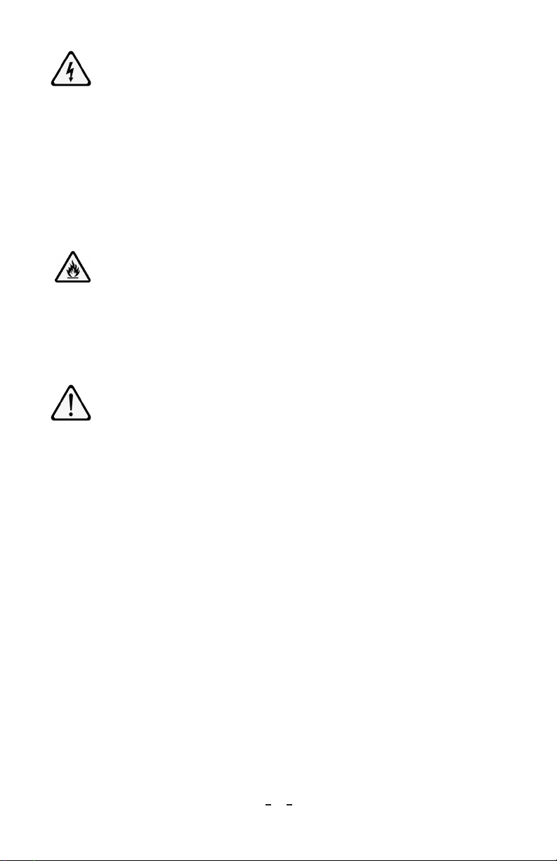
Figure 1. IQ Power HL Control Drawing

6
IQ Power HL Power Supply 5201258 Rev. C
A. Locate at a convenient place within reach of static bar high voltage cable. Power
for AC adapter and an electrical ground connection must be available.
B. Secure to mounting surface (commonly a machine frame) using M5 or M4 [#10
or #8] hardware (not supplied).
NOTE – Do not apply line voltage to AC adapter or Control Station until
installation is complete. Also ensure that all input power switches are in the
OFF (0) position.
WARNING
–
Fire Hazard
Do not install power supply within hazardous (classified) locations. Install in
non-hazardous (unclassified) locations only (see Figure 1).
AVERTISSEMENT
–
Risque d’incendie
Ne pas installer le transformateur à distance des emplacements dangereux
(classifiés). Installer dans des emplacements non dangereux (non classifiés)
seulement (voir Figure 1 ).
Electrical Connections
A. Ground power supply by connecting a ground lead between ground terminal
on flange of power supply and a good electrical machine ground.
B. Connect static bar by cutting high voltage cable to length, terminating leads,
and connecting to power supply: (see Figure 2)
1. Cut HV cable to length, leaving an extra 3¼” for connector.
2. Strip black plastic jacket back 2½”, being careful not to nick insulation of
HV wires. (Practice stripping jacket on waste length of HV cable.)
3. Strip insulation of HV wires back ¾”, being careful not to nick conductor
of HV wire.
4. Straighten conductors and insert into HV connector until conductor
protrudes out from the tip of connector.
5. Solder conductor to tip of connector by applying solder to exposed
conductor. Ensure that the solder does not overflow and fill neck area of tip.
6. Trim off excess conductor protruding from tip of connector.

7
IQ Power HL Power Supply 5201258 Rev. C
Figure 2. Conduit Seal and HighVoltage Cable Terminations
7. Place HV Connectors into HV plug bottom. The black plastic jacket should be
fully engaged in strain relief section of HV plug.
8. Install HV plug top onto bottom making sure plug comes together properly
with no binding or gapping. Hold together firmly.
9. Insert nylon screws through holes in plug bottom and tighten to secure plug
together (do not over tighten screws).
10. Plug in high voltage connector on static bar to HV1 or HV2 on power supply.
Secure high voltage connector with the (2) captive screws on the sides of
connector. Do not over-tighten.
Note that conduit seals must be properly installed to prevent the propagation of
vapors and flames through conduit runs (see Figure 2). Outer (black) jacket of
HV cables must be removed and (white) insulated wires separated) before filling
conduit seals with cement.
NOTE – Use care not to nick or cut insulation on HV wires.
CAUTION – Electrical Shock Hazard
Do not connect static neutralizing bar with power supply energized.
Disconnect input power or switch power off before connecting static bar.
ATTENTION – Risque De Choc
Ne branchez pas la barre de neutralisation statique avec alimentation sous
tension. Couper l’alimentation ou coupez le courant avant de connecter la
barre statique.

8
IQ Power HL Power Supply 5201258 Rev. C
NOTE – Failure to fully seat high voltage connectors into power supply
connectors may result in permanent damage to bar, cable or power supply.
C.
Connect power supply alarm output
(if used). The power supply “Alarm Output”
is a standard DB25 pin connector located on the end of the IQ Power HL Power
Supply. A maximum distance of 3 meters [10 feet] or less is recommended.
Figure 3. IQ Power HL Power Supply Alarm Output
Alarm Output Pin-out
Pin Description Pin Description
1 Remote on/off optocoupler (-) 10 No connection
14 Remote on/off optocoupler (+) 6 No connection
19 No connection
2 Clean Bar Relay (common)* 11 Power Relay (common)*
3 Clean Bar Relay (normally closed)* 7 Power Relay (normally closed)*
16 Clean Bar Relay (normally open)* 20 Power Relay (normally open)*
8 Fault Relay (common)*
4 Fault Relay (normally closed)* 12 Power in (ground)**
17 Fault Relay (normally open)* 24 Power in (ground)**
9 Bar On Relay (common)* 13 Power in (+24 VDC)**
5 Bar On Relay (normally closed)* 25 Power in (+24VDC)**
18 Bar On Relay (normally open)*
*30V 1A Rating on Contacts.
**1.6A Rating, Connect pins 12 & 24 in parallel and 13 & 25 in parallel.
The power supply alarm output provides a variety of relay contact outputs
that indicate the status of the power supply. The relay contacts are rated for
a maximum of 1A at 30 VDC. The alarm output connector also provides a
means of remote power in. (see Figure 3)
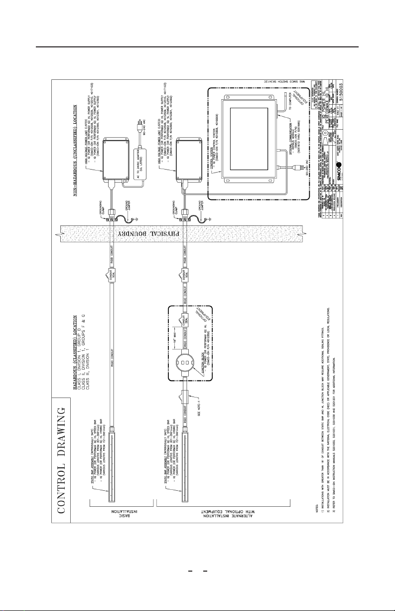
D.
Remote On/Off
Control (if used). The power supply “Alarm Output”
connector also provides for remote on/off control of the power supply. Remote
on/off control is configured with a jumper on a pin header on the main power
supply circuit board. The default configuration is with remote control disabled.
9
IQ Power HL Power Supply 5201258 Rev. C
The remote control can be configured “normally off” or “normally on” by the
jumper setting (refer to Figure 4). To access the jumpers the cover will have to
be removed from the power supply. Disconnect all input power from the power
supply then remove the six screws securing the cover and slowly and carefully
remove the cover.
Remote Control Optocoupler Schematic
Figure 4. Jumper Position at J3 for Remote Control Operation
There is a ribbon cable connecting the face label on cover to the main circuit
board. Use care not to disconnect this cable. If cable becomes disconnected,
lift latches on sides of ribbon cable connector, insert ribbon cable fully into
connector and press latches back down.
10
IQ Power HL Power Supply 5201258 Rev. C
Reposition jumper to enable remote control either “normally on” or “normally
off”, as desired (see Figure 4). Then replace cover and secure with six screws.
When operating a power supply using the remote control circuit, power may
be applied through the “Alarm Output” connector or the “Power In” connector
on end panel. If the “Power In” connector on end panel is used, the “Power”
switch must be set to ON (1) position.
Remote control is established by applying 24 VDC to the “Alarm Output”
connector pins as specified in Figure 4. User-applied 24 VDC drives a low
current optoisolator on the IQ Power HL Power Supply main circuit board,
turning power supply on or off, depending on configuration of jumper J3.
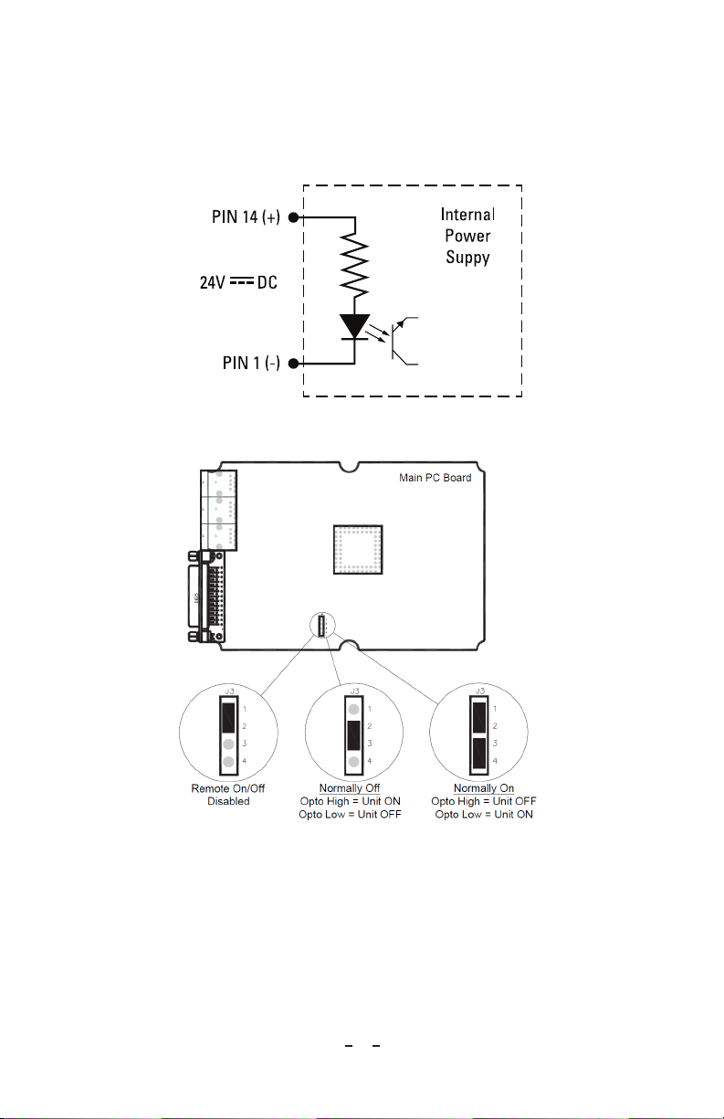
NOTE – DO NOT USE standard Ethernet cables with IQ Power systems.
Avoid permanent equipment damage by using only Simco-Ion modular
cables. (Refer to Section 8, Parts & Accessories).
Figure 5: IQ Power Crossover Modular Cable (black)
E.
Connect AC Adapter
(AC adapter not required if power supply is connected to
a Control Station.) Make sure “POWER” switch on power supply is in “OFF”
(0) position. Route low voltage wire clear of moving machine parts and protect
it from abrasion. Secure using nylon wire ties (not supplied). Do not over
tighten. Insert barrel connector into “POWER IN” connector on power supply.
Hand tighten barrel connector nut to secure.

11
IQ Power HL Power Supply 5201258 Rev. C
Connect line voltage to input side of AC adapter. The AC adapter is a universal
input type that accepts line voltage from 100 to 240 V AC 50/60Hz. The AC
adapter line voltage connector accepts a line cord with an IEC 320 connector
(supplied). The line cord also provides electrical ground to the AC adapter.
Check electrical ground integrity in line voltage receptacle used for AC adapter.
This ground must not be defeated.
High Voltage Connector AC Adapter
Power In Connector
Ground Connection
Line Cord
24 VDC
IQ Power
HL Power Supply
IQ Power HL Static Bar
Conduit and
Conduit Seals
see Control Drawing
5150003
Ground Jumper
Machine Frame Ground
Grounding Clamp
Figure 6. IQ Power Connections (Bar and HL Power Supply)
F. Connect user supplied power (if used). In cases where the user does not want
to use the AC adapter but wants to supply 24 VDC power to the IQ Power HL
Power Supply, user supplied 24 VDC power may be applied two ways.
The “Power In” connector on end panel of IQ Power HL Power Supply may
be used to supply power to the system. This connector requires the use of a
Switchcraft 760K barrel type power plug. The plug should be wired +24 VDC
to center and common (ground) to outer barrel. The common must be bonded
to electrical ground. Wired in this fashion, the “Power” switch on end panel of
power supply is in-circuit.
Alternatively, the “Alarm Output” connector on end panel of IQ Power HL
Power Supply may be used to supply power to the system. This connector
requires the use of a standard DB25 connector. The connector should be wired:
• +24 VDC to pins 13 & 25
• Common (ground) to pins 12 & 24
To ensure current carrying capacity, two pins are used for each connection. The
common must be bonded to ground. Wired in this fashion, the “Power” switch
on end panel of power supply is bypassed. (see Figure 3)
Power supplied in above fashion must have adequate current available to power
HL Power Supply (maximum 1.6A). Input power should be appropriately
fused for safety purposes.

12
IQ Power HL Power Supply 5201258 Rev. C
G.
Connect Control Station
(if used). The Control Station supplies 24 VDC power
for the IQ Power static eliminator power supplies. Use the 2.13 meter [7 foot]
(black) modular cable supplied with unit. Longer cables (not supplied) are
available. Cables must be IQ Power 8-conductor modular cables with RJ-48
connectors wired “crossover” (reference color: black, Figure 5).
The modular cable plugs into one of the connectors labeled “POWER &
COMM” on the Control Station and into either “PS COMM 1” connector on
the HL power supply, see Figure 7.
The modular cable should not be run parallel with static bar high voltage
cable. Route modular cable clear of moving machine parts and protect it from
abrasion. Secure using nylon wire ties (not supplied). Do not over-tighten wire
tie.
If there is an excess of modular cable, do not coil it in vicinity of static bar high
voltage cable. If possible, cut modular cable to length and re-terminate using
an RJ-45 connector installed with the same “polarization” as connector removed
(note rib / wire color code to modular connector).
If multiple IQ Power supplies are connected to the Control Station, each power
supply must have a unique Power Supply Number (address / device number).
This is necessary to enable reliable digital communication.
The Control Station can be used to automatically address the power supplies.
The default Power Supply Number for a new unit is “1”. Plug the first power
supply (only) into the Control Station and turn Control Station on. Allow
Control Station to boot-up and begin operation. Plug second power supply
into Control Station. The Control Station will re-address the second power
supply to “2”. Plug third power supply into Control Station. The Control
Station will re-address the third power supply to “3”. Repeat this process until
all power supplies (or IQ Power / IQ Easy devices) are installed. Each power
supply or device will be given a unique address (device number).
IQ Power HL power supplies may also be manually re-addressed through the
control station.
See Power Supply Number (Address / Device Number) section.

13
IQ Power HL Power Supply 5201258 Rev. C
to PS COMM 1
Connection
Comm / Data Cable Construction
1Crossover Wired Reference color black
DO NOT USE standard Ethernet cables
Ground
Lead
Comm / Power (black)
1
IQ Power
HL Power Supply
to
HV1 or HV2
IQ Power HL Static Bar
Conduit and
Conduit Seals
see Control Drawing
5150003
Ground Jumper
Machine Frame Ground
Grounding Clamp
to CS 1 thru 10
POWER & COMM
to IQ Power device
IQ Power Control Station
to IQ Easy device
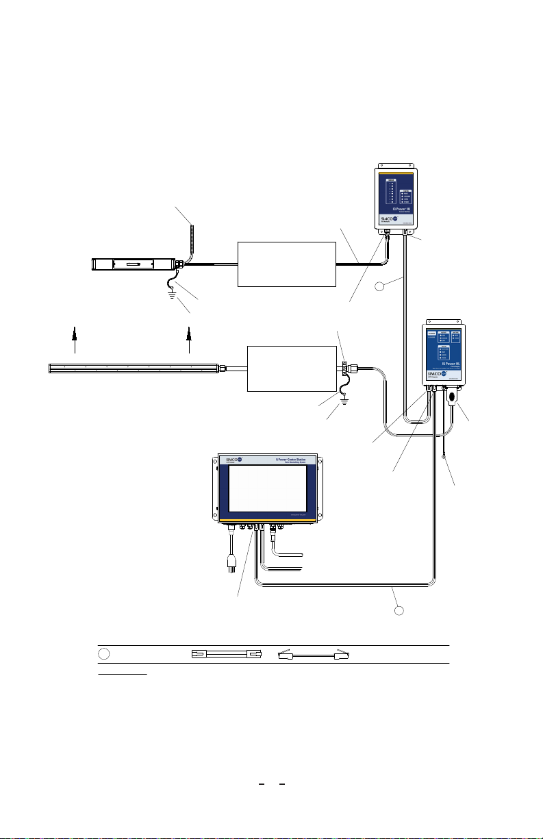
Figure 7. IQ Power Connections (HL Power Supply and Control Station)
H.
Connect Sensor
(if used). An IQ Power HL Sensor may be integrated into the
IQ Power system to provide feedback on static eliminating performance and is
used for the CLFB (Closed-Loop Feedback) static eliminating mode.
Use the 2.13 meter [7 foot] (black) modular cable supplied with Sensor
Interface. Longer cables (not supplied) are available. Cables for Sensor
Interface must be IQ Power 8-conductor modular cables with RJ-48 connectors
wired “crossover” (reference color: black, Figure 5).
The modular cable plugs into one of the connectors labeled “SI COMM 1” on
Sensor Interface and into the “PS COMM 2” connector on HL power supply,
see Figure 8.
The modular cable should not be run parallel with static bar high voltage
cable. Route modular cable clear of moving machine parts and protect it from
abrasion. Secure using nylon wire ties (not supplied). Do not over-tighten wire
tie.
14
IQ Power HL Power Supply 5201258 Rev. C
If there is an excess of modular cable, do not coil it in vicinity of static bar high
voltage cable. If possible, cut modular cable to length and re-terminate using
an RJ-45 connector installed with the same “polarization” as connector removed
(note rib / wire color code to modular connector).
See instructions included with IQ Power HL Sensor for sensor installation.
to PS COMM 2
Connection
to PS COMM 1
Connection
Comm / Data Cable Construction
1Crossover Wired Reference color black
DO NOT USE standard Ethernet cables
Ground
Lead
Comm / Power (black)
1
IQ Power
HL Power Supply
NOTE:
HL Power Supply
and HL Sensor Interface
both report to CS under
HL Power Supply address.
Intrinsic Safety Barriers
see Control Drawing
5150010
IQ Power HL
Sensor Interface
IQ Power
HL Sensor
Ground Jumper
Machine Frame Ground
to SI COMM 1
Connection
To Clean, Dry
Compressed Air Source
if Purge Required
IQ Power HL Power Supply
with IQ Power HL Sensor
typically used for
CLFB mode
Comm / Power (black)
1
to Sensor Port
Connection
to HV1
or HV2
IQ Power HL Sensor Cable
(part of Sensor)
Conduit and
Conduit Seals
see Control Drawing
5150003
Ground Jumper
Machine Frame Ground
Grounding Clamp
IQ Power HL Static Bar
Web Direction of Travel
Minimum 12" Downstream
to CS 1 thru 10
POWER & COMM
to IQ Power device
IQ Power Control Station
to IQ Easy device
Figure 8. IQ Power Connections (HL Power Supply with Sensor Interface and Control Station)

15
IQ Power HL Power Supply 5201258 Rev. C
Power Supply Number (Address / Device Number)
Each IQ Power HL power supply has an address (number) associated with it. These
numbers serve to identify the power supply in digital communications. This address
can be a number of 1 through 10 (the default is “1”).
If a Sensor Interface is wired to the HL power supply, the Sensor data will also report
using the HL power supply Address number. They will appear on the Control
Station as a single device with multiple tabs.
The power supply address numbers may be manually adjusted or may be
automatically set by the Control Station. Having multiple power supplies with the
same address number connected to a Control Station is not permitted.
To manually adjust power supply address, connect unit by itself to a Control
Station. Turn the Control Station on and allow the Control Station to begin
running. Tap the device icon for the HL power supply. Tap the Neutralizer
tab. Tap the right arrow to get to page 2. Locate and tap the editing pencil icon
for Device Address. You will be prompted to enter the Control Station password
(default password is “password”). A touch pad will appear that may be used to
manually set the power supply address. The power supply will flicker its indicator
lights to confirm setting of the power supply address. Note: if a Sensor Interface is
paired with the power supply, but not connected to the power supply, its address
will also have to be changed manually by tapping the Sensor tab and tapping the
right arrow to get to page 4.
To automatically set power supply address, use the Control Station. The default
Power Supply Number for a new unit is “1”. Plug first power supply (only) into
Control Station and turn Control Station on. Allow Control Station to boot-up
and begin operation. Plug second power supply into Control Station. The Control
Station will re-address second power supply to “2”. Plug third power supply into
Control Station. The Control Station will re-address third power supply to “3”.
Repeat this process until all power supplies (or IQ Power / IQ Easy devices) are
installed. Each power supply or device will be given a unique address (device
number).
Set Up (with IQ Power Control Station)
A variety of information can be checked, and operating parameters set, for the IQ
Power HL power supply through the IQ Power Control Station via the device page.
Tap on device icon for the HL power supply and static bar to access these pages. A
summary tab will appear offering important information. Tabs for the neutralizer
and sensor (if installed) will also appear. Tapping on a neutralizer tab or sensor
tab opens a page where operating parameters may be edited or selected. Typical
parameters are listed below.

16
IQ Power HL Power Supply 5201258 Rev. C
Device Name
: A user editable name to identify specific device (14 character).
Bar Type
: A fixed description for the type of bar connected to the HL power supply
(speed or hybrid).
Bar HV
: Allows turning internal HV power supplies on / off.
Ion Output
: Displays the ionization level, in percent, where Bar Calibration =
100% and the ionization level in terms of microamps for both positive and negative
ionization.
Balance
: A ratio of input power supplied to the high voltage power supplies that is
related to ion balance. In Fixed, Auto-Tune and CLFB modes this is a display only
and non-editable. The Balance may only be user adjusted in the Manual mode.
Operation Mode
: A user selectable operating mode for the static bar (Manual, Fixed,
Auto-Tune, CLFB).
•
Fixed
- 50/50 balance standard operation (default factory setting). Fixed
provides standard operation, with output voltage regulation.
•
Auto-Tune
- Enhanced operation. This mode includes the current
monitoring found in Fixed mode, plus automatic compensation that takes
into account web speed, bar type, bar mounting distance and measured
ion current to optimize static neutralization performance. In order to
successfully invoke Auto-Tune, certain operating parameters must be
defined:
– Web Speed will have to be entered by the user.
– Mounting Distance will have to be entered by the user. It is the distance
between face of static neutralizing bar and web, or material to be
neutralized.
•
CLFB (Closed-Loop Feedback)
- The best control of ion balance. The IQ
Power HL Sensor connected to an HL power supply will automatically
pair with that power supply for closed loop control. The sensor must
be downstream of the static neutralizing bar in order for CLFB to work.
The sensor detects any voltage imbalance on the web, or material to be
neutralized, then transmits this information to the static neutralizing power
supply. The power supply makes incremental changes to the balance setting
until downstream charges are minimized.
•
Manual
- Allows manual control of the ion balance. Manual mode includes
voltage regulation and current monitoring found in the standard mode, plus
manual control of the ion balance ratio. This mode of operation would
only be selected where the web, or material to be neutralized, exhibited
extreme and consistent charging of one polarity.
Mounting Distance
: A user editable dimension, the spacing between face of bar and
web (surface being neutralized / measured). The factory default mounting distance
for neutralizing bars is 4” (100 mm) for speed type bars and 6” (150 mm) for hybrid

17
IQ Power HL Power Supply 5201258 Rev. C
type bars. This is only used in the Auto-Tune mode. The mounting distance may
be set for individual HL Sensors. The factory default mounting distance for sensors
is 4” (100 mm).
NOTE – This information (Mounting Distance) MUST be correct. It is
used by the static neutralizing bar when in Auto-Tune mode and used by the
static sensor for calibration. If this information is not correct, the static bar
may not operate properly when in the Auto-Tune mode or the static sensor may
report incorrect web voltages.
Web Speed
: A user entered value used only in the Auto-Tune mode.
Device Address:
The Power Supply Number (address / device number) assigned to
the HL power supply. The address may be edited, but duplicate address numbers
are not permitted. The exception to this rule is static sensors. When a static Sensor
Interface is connected to an HL power supply (PS COMM 2) the Sensor Interface
will automatically be assigned the same address number as the HL power supply.
On the Control Station, the data from Sensors connected to that Sensor Interface
will appear as a tab under the HL power supply and the interface will automatically
be paired with that HL power supply for CLFB operation.
If a Sensor Interface is not connected to an HL power supply, but is assigned the
same address, it will be paired to that HL power supply.
Sensor Quantity
: The number of sensors found on sensor interface.
Overall Sensor Avg
: The average voltage reported by all sensors on a sensor interface.
Feedback Sensor Avg
: The feedback voltage for use in CLFB control.
This is determined by using Sensors for Feedback, a user adjustable operating
parameter.
Warning Setpoint
: The web voltage level at which sensor interface will set a
“Warning” and illuminate yellow indicator light on interface. The factory default
value is 5 kV, however this value may be user adjusted.
Alarm Setpoint
: The web voltage level at which sensor interface will set an “Alarm”
and illuminate red indicator light on interface. The factory default value is 20 kV,
however this value may be user adjusted.
Web Voltage Sensor 1,2,3
…: The voltage level reported by a given sensor.
Device Version
: The firmware revision in device.
Device Locater Utility
: Causes indicator lights on device (power supply) to flicker for
a brief time to aid in verifying location of a given device.
Alarm Test Utility
: Causes an alarm output to aid in checking/troubleshooting alarm
sensing connections.

18
IQ Power HL Power Supply 5201258 Rev. C
Device Calibration: Displays the time and date of last calibration and allows for
calibration of the power supply and bar. Calibration is used to set the output level
to 100% with the bar at maximum output (maximum output varies with bar length
and operating conditions).
Clean Bar Threshold – Displays the threshold in output level percent used to set
the clean bar alarm and allows for setting of the clean bar threshold.
Table of contents
Other Simco-Ion Power Supply manuals


Popular Power Supply manuals by other brands


Thermal Dynamics
Thermal Dynamics Pak Master 75XL Plus operating manual

MAASLAND
MAASLAND KSG1C quick start guide

Siemens
Siemens MICROMASTER 430 FX Maintenance Instruction

Techroutes
Techroutes TSR 2800-10C Hardware installation manual

Emerson
Emerson NetSure-48 VDC Power System installation instructions

ESAB
ESAB EPP-400 manual