PerfecTron OXY5638B User manual

Version 1.2
Revision Date: June. 30. 2017
www.perfectron.com
OXY5638B
Intel® Broadwell-U EPIC SBC
User's Manual

OX5638B User's Manual V1.2
www.perfectron.com
Safety Information
1. Electrical safety
•To prevent electrical shock hazard, disconnect the power cable from the electrical outlet before
relocating the system.
•When adding or removing devices to or from the system, ensure that the power cables for the
devices are unplugged before the signal cables are connected. If possible, disconnect all power
cables from the existing system before you add a device.
•Before connecting or removing signal cables from the motherboard, ensure that all power
cables are unplugged.
•Seek professional assistance before using an adapter or extension cord. These devices could
interrupt the grounding circuit.
•Make sure that your power supply is set to the correct voltage in your area.
•If you are not sure about the voltage of the electrical outlet you are using, contact your local
power company.
•If the power supply is broken, do not try to fix it by yourself. Contact a qualified service
technician or your local distributor.
2. Operation safety
•Before installing the motherboard and adding devices on it, carefully read all the manuals that
came with the package.
•Before using the product, make sure all cables are correctly connected and the power cables
are not damaged. If you detect any damage, contact your dealer immediately.
•To avoid short circuits, keep paper clips, screws, and staples away from connectors, slots,
sockets and circuitry.
•Avoid dust, humidity, and temperature extremes. Do not place the product in any area where it
may become wet.
•Place the product on a stable surface.
•If you encounter any technical problems with the product, contact your local distributor
Statement
•All rights reserved. No part of this publication may be reproduced in any form or by any means,
without prior written permission from the publisher.
•All trademarks are the properties of the respective owners.
•All product specifications are subject to change without prior notice
1

OX5638B User's Manual V1.2
www.perfectron.com
Revision History
Revision
Date(yyyy/mm/dd)
Changes
1.0
2017/03/14
Initial release
1.1
2017/06/19
Update block diagram
Update JUSB, LVDS_PWR, LAN12 and COM1 pin define
Add connector P/N
1.2
2017/6/30
Add Section 2.2 Onboard and mating connector types
Packing list
□OXY5638B EPIC SBC
□CD (Driver + user's manual)
Optional Accessories
□Cable Kits
If any of the above items is damaged or missing, please contact your local
distributor.
2

OX5638B User's Manual V1.2
www.perfectron.com
Table of Contents
Safety Information .................................................................................................................................1
1. Electrical safety ..........................................................................................................................1
2. Operation safety.........................................................................................................................1
Statement...............................................................................................................................................1
Revision History......................................................................................................................................2
Packing list..............................................................................................................................................2
Optional Accessories..............................................................................................................................2
Table of Contents ...................................................................................................................................3
Chapter 1: Product Information.............................................................................................................6
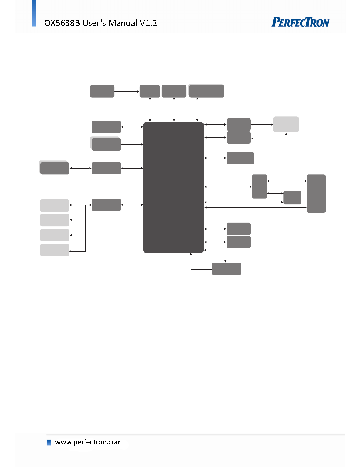
1.1 Block Diagram ..........................................................................................................................6
1.2 Key Features.............................................................................................................................7
1.3 Board Placement......................................................................................................................8
Chapter 2: Jumpers, Connectors and Switch .........................................................................................9
2.1 Jumpers and connectors list.....................................................................................................9
2.2 Onboard and mating connector types...................................................................................10
2.3 Jumper Setting .......................................................................................................................11
JP1901: LVDS Resolution ......................................................................................................11
JP1902: LVDS +5V/+3.3V Voltage Select...............................................................................11
JP1903: LVDS Backlight Control............................................................................................11
JP2701: .................................................................................................................................12
JP2702: .................................................................................................................................12
JP2703: .................................................................................................................................12
JP2704: .................................................................................................................................12
JP2707: LVDS Backlight +5V/+3.3V Voltage Select...............................................................13
JCMOS: CMOS Clear.............................................................................................................13
2.4 Connector...............................................................................................................................14
DCIN: DC-IN +12V.................................................................................................................14
AUDIO1.................................................................................................................................14
AUDIO...................................................................................................................................14
BAT1 .....................................................................................................................................15
LPC........................................................................................................................................15
SATA1....................................................................................................................................15
SATA2....................................................................................................................................15
SATA_PWR ............................................................................................................................16
DIO1 .....................................................................................................................................16
DIO2 .....................................................................................................................................16
COM1 : RS232/422/485 Select in BIOS ................................................................................17
3

OX5638B User's Manual V1.2
www.perfectron.com
COM2 : RS232 ......................................................................................................................17
COM3 : RS232 ......................................................................................................................17
COM4 : RS232 ......................................................................................................................17
USB45...................................................................................................................................18
USB67...................................................................................................................................18
JUSB1....................................................................................................................................19
LVDS......................................................................................................................................19
LVDS_PWR............................................................................................................................20
LAN12...................................................................................................................................20
LAN_LED...............................................................................................................................21
SIM_CARD1 ..........................................................................................................................21
SIM_CARD2 ..........................................................................................................................21
MINI_PCIE1 ..........................................................................................................................22
MINI_PCIE2 (support mSATA) ..............................................................................................22
FP1: HDD LED/Power LED/Reset BTN/Power BTN ...............................................................22
DP.........................................................................................................................................23
CPUFAN ................................................................................................................................23
DIMMA: 240-pin XR-DIMM Slot...........................................................................................24
DIMMB: 240-pin XR-DIMM Slot...........................................................................................24
STACKPC: Connector A Top...................................................................................................25
Chapter 3: AMI BIOS UTILITY ...............................................................................................................26
3.1 Starting...................................................................................................................................26
3.2 Navigation Keys ......................................................................................................................26
3.3 Main Menu.............................................................................................................................27
3.4 Advanced Menu .....................................................................................................................28
3.4.1 CPU Configuration.......................................................................................................29
3.4.2 Trust Computing..........................................................................................................30
3.4.3 ACPI Setting.................................................................................................................30
3.4.4 AMT Setting.................................................................................................................31
3.4.5 IT8786 Super IO Configuration....................................................................................31
3.4.5.1 Serial Port 1 Configuration...............................................................................32
3.4.5.2 Serial Port 2 Configuration...............................................................................32
3.4.5.3 Serial Port 3 Configuration...............................................................................33
3.4.5.4 Serial Port 4 Configuration...............................................................................33
3.4.6 Hardware Monitor ......................................................................................................34
3.4.7 F81216SEC Super IO Configuration.............................................................................34
3.4.8 SATA Configuration......................................................................................................35
3.4.9 USB Configuration.......................................................................................................35
4

OX5638B User's Manual V1.2
www.perfectron.com
3.4.10 Intel I218-LM Ethernet Controller.............................................................................36
3.4.10.1 NIC Configuration...........................................................................................36
3.4.11 Intel I210-IT Ethernet Controller...............................................................................37
3.4.11.1 NIC Configuration...........................................................................................37
3.5 Chipset Menu.........................................................................................................................38
3.5.1 System Agent (SA) Configuration ................................................................................38
3.5.1.1 Graphics Configuration ....................................................................................39
3.5.1.1.1 LCD Control ...........................................................................................39
3.5.1.2 Memory Configuration.....................................................................................40
3.5.2 PCH-IO Configuration..................................................................................................40
3.5.2.1 PCH Azalia Configuration .................................................................................41
3.5.2.2 BIOS Security Configuration.............................................................................41
3.5.2.3 Restore AC Power Loss.....................................................................................42
3.5.2.4 Wake on LAN (I218) .........................................................................................42
3.6 Security Menu ........................................................................................................................43
3.7 Boot Menu .............................................................................................................................44
3.7.1 Boot Option.................................................................................................................44
3.8 Save & Exit..............................................................................................................................45
5

OX5638B User's Manual V1.2
www.perfectron.com
Chapter 1: Product Information
1.1 Block Diagram
6
eDP
LVDS
UART1
UART2
UART3
UART4
USB 2.0
LAN
2x15pin
i218-LM
DDR3L 1333/1600
XR-DIMM
DP 2x15pin
CH7511B
LVDS
2x15 pin
i210-IT
SATA
SATA
nanoSSD
64GB
HDA
ALC888
Codec
COM1
RS232/422/485
COM2
2x5 pin RS232
COM3
2x5 pin RS232
COM4
2x5 pin RS232
IT8786E
Super IO
SATA
Connector
mPCIe
mPCIe/mSATA
PEX8606
USB 2.0
PCIe x1
PCIe x1
PCIe x1
PCIe x1
4 x PCIe
PCIe x4
USB
2x5 pin
USB 2.0
USB 2.0 USB
2x5 pin
USB 2.0
USB 3.0 Box Header
2x10 pin
Broadwell-U
FCBGA1168
40x24mm
DDI DDR3L
PCIe/104
(Stack PC)
PCIe x1
Audio
1 x 10 pin

OX5638B User's Manual V1.2
www.perfectron.com
1.2 Key Features
System
CPU Type
Intel® CoreTM i3-5010U (3M Cache, up to 2.10GHz, 15W)
Intel® CoreTM i5-5350U (3M Cache, up to 2.90GHz, 15W)
Intel® CoreTM i7-5650U (4M Cache, up to 3.20GHz, 15W)
Memory Type
2 x XR-DIMM up to 16 GB
NAND Drive
64 GB SATA NAND Onboard
BIOS
AMI® UEFI BIOS
Watchdog
1-255 sec. or 1-255 min. software programmable
Can generate system reset
Expansion
PCIe104 (StackPC): 1 x PCIe_4, 4 x PCIe_1
2 x mPCIe (1 with mSATA supported)
Display
Chipset
Intel® HD Graphics
LVDS
Dual Channel 24-bit LVDS
Display Type
LVDS, DP
Audio
Codec
Realtek ALC888S High Definition Audio Codec
Ethernet
Chipset
1 x Intel® I210-IT
1 x Intel® I218-LM
WOL
Yes
Boot from LAN
Yes for PXE
Internal I/O
SATA
2 x SATAIII
COM
3 x RS232 with 5V/12V selection
1 x RS232/422/485 with 5V/12V selection
Ethernet
2
USB 3.0
2
USB 2.0
4
SIM card holder
2
DIO
2
LPC
1
LVDS
1
Audio
2 x (1 x 10)pin for Line-out, Line-in, 2 x Mic-in(optional)
Mechanical and Environment
Form Factor
EPIC SBC
Power Type
12V DC-in
Dimension
180 mm x 115 mm
Operating Temp.
-40 to 85°C
Storage Temp.
-40 to 85°C
Relative Humidity
10% to 90%, non-condensing
*All specifications and photos are subject to change without notice.
7

OX5638B User's Manual V1.2
www.perfectron.com
1.3 Board Placement
8

OX5638B User's Manual V1.2
www.perfectron.com
Chapter 2: Jumpers, Connectors and Switch
2.1 Jumpers and connectors list
Label
Function
JP1901
LVDS Resolution
JP1902
LVDS Voltage
JP1903
LVDS Backlight Control
JP2701
COM1 RI-/+5V/+12V Selection
JP2702
COM2 RI-/+5V/+12V Selection
JP2703
COM3 RI-/+5V/+12V Selection
JP2704
COM4 RI-/+5V/+12V Selection
JP2707
Backlight Control Power
JCMOS
CMOS Clear
SW1
Power type and delay On/Off Selection
DCIN
4P Power Input Connector
AUDIO1
Mic, Line-in
AUDIO
Mic, Line-in, Line-out
BAT1
Battery connector
LPC
LPC
SATA1
SATAIII connector
SATA2
SATAIII connector
SATA_PWR
SATA Power
COM1
RS232/422/485
COM2
RS232
COM3
RS232
COM4
RS232
DIO1
8-bit DIO
DIO2
8-bit DIO
USB45
2 x USB2.0
USB67
2 x USB2.0
JUSB1
2 x USB3.0
LVDS
24-bit LVDS
LVDS_PWR
LVDS Power
LAN12
2 x GbE LAN
LAN_LED
LAN LED
MINI_PCIE1
Full-size mPCIe slot
MINI_PCIE2
Full-size mPCIe/mSATA slot
SIM_CARD1
Standard SIM card holder
9

OX5638B User's Manual V1.2
www.perfectron.com
SIM_CARD2
Standard SIM card holder
FP1
Front Panel
DP
2 x DisplayPort
CPUFAN
CPU Fan
DIMMA
240-pin XR-DIMM Slot
DIMMB
240-pin XR-DIMM Slot
STACKPC
PCIe/104 Connector Top
2.2 Onboard and mating connector types
Connector
Onboard Connector
Mating Connectors/Cables
Manufacturer
Type Number
Manufacturer
Type Number
DCIN
PHOENIX
1776715
PHOENIX
1786857
LPC
YIMTEX
501MW1*10ST-1R
MOLEX
51021-1000
SATA_PWR
PINREX
743-81-04TW00
Perfectron Cable
(200mm)
0C5020014070300L
COM1, COM2,
COM3, COM4
YIMTEX
501MW1*10ST-1R
MOLEX
51021-1000
Perfectron Cable
(DB9, 150mm)
0C5020005101100L
AUDIO1, AUDIO
YIMTEX
501MW1*10ST-1R
MOLEX
51021-1000
DIO1, DIO2
PINREX
520-90-10GB00
JST
PHDR-10VS
USB45, USB67
PINREX
712-73-10TWE0
MOLEX
51021-1000
Perfectron Cable
(100mm)
0C50200YBW1611EL
JUSB1
PINREX
52X-40-20GU52
Perfectron Cable
(150mm)
0C50200YBW1611DL
LVDS
ACES
87216-3004
ACES
87219-3004
LVDS_PWR
PINREX
712-73-10TWE0
MOLEX
51021-1000
LAN12
MOLEX
501190-3017
MOLEX
501189-3010
LAN_LED
YIMTEX
501MW1*10ST-1R
MOLEX
51021-1000
FP1
PINREX
222-97-05GBE2
JST
PHDR-10VS
DP
MOLEX
501190-3017
MOLEX
501189-3010
CPUFAN
FOXCONN
HF2704E-M1
AMP
1375820-4
10

OX5638B User's Manual V1.2
www.perfectron.com
2.3 Jumper Setting
JP1901: LVDS Resolution
HA
(Pixel)
VA
(Line)
Color
depth
Channel
Setting
Drawing
Jumper
1-2
Jumper
3-4
Jumper
5-6
Jumper
7-8
800
600
18-bit
Single
Shorted
Shorted
Shorted
Shorted
1024
768
18-bit
Single
Shorted
Shorted
Shorted
Opened
1024
768
24-bit
Single
Shorted
Shorted
Opened
Shorted
1280
800
18-bit
Single
Shorted
Shorted
Opened
Opened
1280
1024
24-bit
Dual
Shorted
Opened
Shorted
Shorted
1366
768
24-bit
Single
Shorted
Opened
Shorted
Opened
1440
900
24-bit
Dual
Shorted
Opened
Opened
Shorted
1920
1080
24-bit
Dual
Shorted
Opened
Opened
Opened
JP1902: LVDS +5V/+3.3V Voltage Select
Jumper
Function description
Setting
1-2
3.3V
2-3
5.0V
Default setting: 2-3
JP1903: LVDS Backlight Control
PIN
DEFINITION
1
GND
2
Backlight UP
3
Backlight Down
4
GND
11

OX5638B User's Manual V1.2
www.perfectron.com
JP2701:
PIN
DEFINITION
PIN
DEFINITION
1
COM1_RI-
2
COM1P9SEL
3
+5VS
4
COM1P9SEL
5
12V
6
COM1P9SEL
Default setting: 1-2
JP2702:
PIN
DEFINITION
PIN
DEFINITION
1
COM2_RI-
2
COM2P9SEL
3
+5VS
4
COM2P9SEL
5
12V
6
COM2P9SEL
Default setting: 1-2
JP2703:
PIN
DEFINITION
PIN
DEFINITION
1
COM3_RI-
2
COM3P9SEL
3
+5VS
4
COM3P9SEL
5
12V
6
COM3P9SEL
Default setting: 1-2
JP2704:
PIN
DEFINITION
PIN
DEFINITION
1
COM4_RI-
2
COM4P9SEL
3
+5VS
4
COM4P9SEL
5
12V
6
COM4P9SEL
Default setting: 1-2
12

OX5638B User's Manual V1.2
www.perfectron.com
JP2707: LVDS Backlight +5V/+3.3V Voltage Select
Jumper
Function description
Setting
1-2
3.3V
2-3
5.0V
Default setting: 1-2
JCMOS: CMOS Clear
Jumper
Function description
Setting
1-2
Default
2-3
Clear CMOS
13

OX5638B User's Manual V1.2
www.perfectron.com
2.4 Connector
DCIN: DC-IN +12V
[Phoenix 1776715]
PIN
DEFINITION
1
+VIN
2
+VIN
3
GND
4
GND
AUDIO1
[YIMTEX 501MW1*10ST-1R]
1 x 10 pin, pitch = 1.25 mm
PIN
DEFINITION
1
GND
2
MIC2_JD
3
MIC2_R
4
MIC2_L
5
N/A
6
N/A
7
N/A
8
LINE2_JD
9
LINE2_R
10
LINE2_L
AUDIO
[YIMTEX 501MW1*10ST-1R]
1 x 10 pin, pitch = 1.25 mm
PIN
DEFINITION
1
GND
2
MIC1_JD
3
MIC1_R
4
MIC1_L
5
FRONT_JD
6
FRONT_R
7
FRONT_L
8
LINE1_JD
9
LINE1_R
10
LINE1_L
14

OX5638B User's Manual V1.2
www.perfectron.com
BAT1
[PINREX 712-73-02TWR0]
PIN
DEFINITION
1
1
GND
2
+3v
LPC
[YIMTEX 501MW1*10ST-1R]
1 x 10 pin, pitch = 1.25 mm
PIN
DEFINITION
1
GND
2
TPM_IRQ
3
+3.3VSB
4
LPC_AD0
5
LPC_AD1
6
LPC_AD2
7
LPC_AD3
8
LPC_FRAME#
9
PLTRST#_BUF1
10
LPC_CLK_1
SATA1
SATA2
PIN
DEFINITION
1
GND
2
TXP
3
TXN
4
GND
5
RXN
6
RXP
7
GND
15

OX5638B User's Manual V1.2
www.perfectron.com
SATA_PWR
[PINREX 743-81-04TW00]
PIN
DEFINITION
1
+5V
2
GND
3
GND
4
+12V
DIO1
[PINREX 520-90-10GB00]
2 x 5 pin, pitch = 2 mm, 2 mm
PIN
DEFINITION
PIN
DEFINITION
1
DIO0
2
DIO1
3
DIO2
4
DIO3
5
DIO4
6
DIO5
7
DIO6
8
DIO7
9
+5V
10
GND
DIO2
[PINREX 520-90-10GB00]
2 x 5 pin, pitch = 2 mm, 2 mm
PIN
DEFINITION
PIN
DEFINITION
1
DIO8
2
DIO9
3
DIO10
4
DIO11
5
DIO12
6
DIO13
7
DIO14
8
DIO15
9
+5V
10
GND
16

OX5638B User's Manual V1.2
www.perfectron.com
COM1 : RS232/422/485 Select in BIOS
[YIMTEX 501MW1*10ST-1R]
1 x 10 pin, pitch = 1.25 mm
PIN
DEFINITION
Mode
RS232
RS422
RS485
1
+5V
+5V
+5V
2
Ground
Ground
Ground
3
RI(Default)/+5V/+12V
4
DTR-
RXD-
5
CTS-
6
TXD
RXD+
7
RTS-
8
RXD
TXD+
D+
9
DSR-
10
DCD-
TXD-
D-
COM2 : RS232
COM3 : RS232
COM4 : RS232
[YIMTEX 501MW1*10ST-1R]
1 x 10 pin, pitch = 1.25 mm
PIN
DEFINITION
1
+5V
2
Ground
3
RI(Default)/+5V/+12V
4
DTR-
5
CTS-
6
TXD
7
RTS-
8
RXD
9
DSR-
10
DCD-
17

OX5638B User's Manual V1.2
www.perfectron.com
USB45
[PINREX 712-73-10TWE0]
1 x 10 pin, pitch = 1.25 mm
PIN
DEFINITION
1
+5V
2
USB4_D-
3
USB4_D+
4
Ground
5
Ground
6
+5V
7
USB5_D-
8
USB5_D+
9
Ground
10
Ground
USB67
[PINREX 712-73-10TWE0]
1 x 10 pin, pitch = 1.25 mm
PIN
DEFINITION
1
+5V
2
USB6_D-
3
USB6_D+
4
Ground
5
Ground
6
+5V
7
USB7_D-
8
USB7_D+
9
Ground
10
Ground
18

OX5638B User's Manual V1.2
www.perfectron.com
JUSB1
[PINREX 52X-40-20GU52]
PIN
DEFINITION
PIN
DEFINITION
1
+5V_UBS0
11
USB1_D+
2
USB3_P1_RX_N
12
USB1_D-
3
USB3_P1_RX_P
13
GND
4
GND
14
USB3_P2_TX_P
5
USB3_P1_TX_N
15
USB3_P2_TX_N
6
USB3_P1_TX_P
16
GND
7
GND
17
USB3_P2_RX_P
8
USB0_D-
18
USB3_P2_RX_N
9
USB0_D+
19
+5V_UBS1
10
id
LVDS
[ACES 87216-3004]
# Mated with [ACES 87219-3004]
PIN
DEFINITION
PIN
DEFINITION
1
LVDS_BCLK
2
GND
3
LVDS_BCLK#
4
LVDS_A3
5
GND
6
LVDS_A3#
7
LVDS_B3
8
GND
9
LVDS_B3#
10
LVDS_ACLK
11
LVDS_B2
12
LVDS_ACLK#
13
LVDS_B2#
14
GND
15
LVDS_B1
16
LVDS_A2
17
LVDS_B1#
18
LVDS_A2#
19
LVDS_B0
20
LVDS_A1
21
LVDS_B0#
22
LVDS_A1#
23
GND
24
LVDS_A0
25
LVDS_DDC_SC
26
LVDS_A0#
27
LVDS_DDC_SD
28
GND
29
LVDS_VDD
30
LVDS_VDD
19
Table of contents
Other PerfecTron Motherboard manuals

PerfecTron
PerfecTron OXY5313A User manual

PerfecTron
PerfecTron OXY5740C User manual

PerfecTron
PerfecTron OXY5737A User manual

PerfecTron
PerfecTron OXY5363A User manual

PerfecTron
PerfecTron OXY5316A User manual

PerfecTron
PerfecTron INS8365B User manual

PerfecTron
PerfecTron INS8143A User manual

PerfecTron
PerfecTron INS8370A User manual

PerfecTron
PerfecTron OXY5320A User manual

PerfecTron
PerfecTron INS8145A User manual