ELGO Electric SERIES P8721-000-P User manual

SERIES P8721-000-P
P8721-000-P-E_25-04.doc Doku Art. Nr. 799000143
Single Axis Position Controller
− PID-analog output (+/- 10 V)
and
2 or 3 switched speed positioning
− 200 address line program memory
− manual operation
− single set operation
− auxiliary functions

2
1. SHORT DESCRIPTION 4
2. FUNCTIONS 5
2.1 Two speed operation (switched) 5
2.2 Three speed operation (switched) 5
2.3 Option PID-analog +/- 10 V output (regulated) 6
2.4 Setting Datum/Reference 6
2.4.1 Operation of Go to Datum 6
2.6 Encoder monitoring 7
2.7 Batch counter 7
2.8 Program counter 7
2.8.1 Auxiliary Functions 8
2.9 Fault monitoring 8
3. FRONT PANEL 9
3.1 Functions of Display 9
3.2 Functions of LED’s 9
3.3 Function of the Keypad 10
4. CONTROLLER IN OPERATION 12
4.1 Single set operation 12
4.2 Program Operation (R8/4 = 0) 12
4.2.1 Selection of a Program Block 12
4.2.2 Enter a program 13
4.3 Table operation mode (R8/4 =1) 13
4.3.1 Operation in Table mode 13
4.4 Manual operation 14
5. REGISTER INPUT 14
5.1 Unlocking Registers by Security Code 14
5.2 Setting and Changing Register Values 15

3
5.3 Locking of Registers 15
6. REGISTER LIST 16
7. DESCRIPTION OF REGISTERS 17
R8 - System Register 1 18
7.1 Backlash positioning 19
7.2 Output configurations 20
R18 - System Register 2 24
R24 – Forced loop range window 25
R25 - Fixed Position (PID only) 25
R28 - System Register 3 26
Parameters for Analog (PID) Control (R50-R58): 28
R88 - System Register 4 30
R99 - ONLY FOR SERVICE 31
8. POSITIONING WITH ANALOG PID OUTPUT 32
8.1. Offset adjustment of closed loop analog system 32
8.2 SETTING OF ANALOG PARAMETERS 33
9. FUNCTIONS OF THE INPUTS (CONNECTOR ST3) 34
10. FUNCTIONS OF THE OUTPUTS 35
11. CONNECTIONS 36
11.1 Connector assignment (Rear) 37
12. TECHNICAL SPECIFICATIONS 37
13. INSTALLATION/WIRING 38
14. TYPE DESIGNATION 39
15. LIABILITY EXCLUSION / GUARANTEE 40

4
1. Short Description
Whilst the P8721-000-P with option Analog-output is specifically designed to provide closed loop
(proportional, integral, differential) analog control of 4 quadrant drives, it also serves the purpose of
operating as a 2 or 3 speed controller, as the P8721-000-R.
When used as a closed loop controller, it is essential that:
A 4 quadrant drive – usually a high dynamic servo drive, is used.
The drive is capable of accepting a +/- reference signal for direction, without a dead-band.
The encoder is torsional rigidly coupled to motor.
The mechanics of the machine are backlash-free.
Whilst it is possible to use lower specification drives and mechanics, it may then not always be possible to
achieve the performance and accuracy which is commonly expected of a closed loop system.
When using a simple inverter driven AC motor, it is essential to use the drive in F/V or FCC mode, rather
than the full Flux Vector (which tends to fight the position controller at low speeds).
Physically, the P8721-000-P connections are compatible with the “old” 87P/P8721PID 2 or 3 switched
speed controller. It may also be more attractive when coupled to a PLC, when relays are not required. It
is necessary to use this model, when Auxiliary Functions are required.
As a 2 or 3 speed positioning system, it has the following features: -
• Absolute and incremental positioning modes
• Operation in 200 lines program mode
• Single set operation
• Manual operation, slow and fast mode
• Batch counter with completed output
• Auxiliary outputs
• Pulse multiplicator
• Datum/reference setting routines
• Tool offset compensation in incremental mode
• Incremental error compensation
• Backlash/Spindle compensation
• Tolerance window blanking
• Encoder monitoring
• max. input frequency 20 kHz
The unit is suitable for operation with any type of 2 or 3 speed bi-directional drive or any variable speed
drive with 1, 2 or 4 quadrant of control.
The performance and accuracy obtained is dependent on the type of drive chosen.
The outputs for stepped speed drives are transistors. These outputs can be configured in a number of
ways to suit all types of control circuits. Actual position is monitored by an incremental Encoder. The
power supply unit is external. If relays are required, an external relay card can be provided. The
controller can be used to position machinery to any desired absolute position. Alternatively, the controller
can be used to feed material through a process.
As an analog closed loop controller, it has the additional features of :-
• PID- analog output +/- 10 V
• Top speed setting
• Acceleration/Deceleration rate settings
• PID term optimisation
• Go to Datum routines
5
2. Functions
The P8721-000-P can be configured for switched speed or regulated PID-analog output.
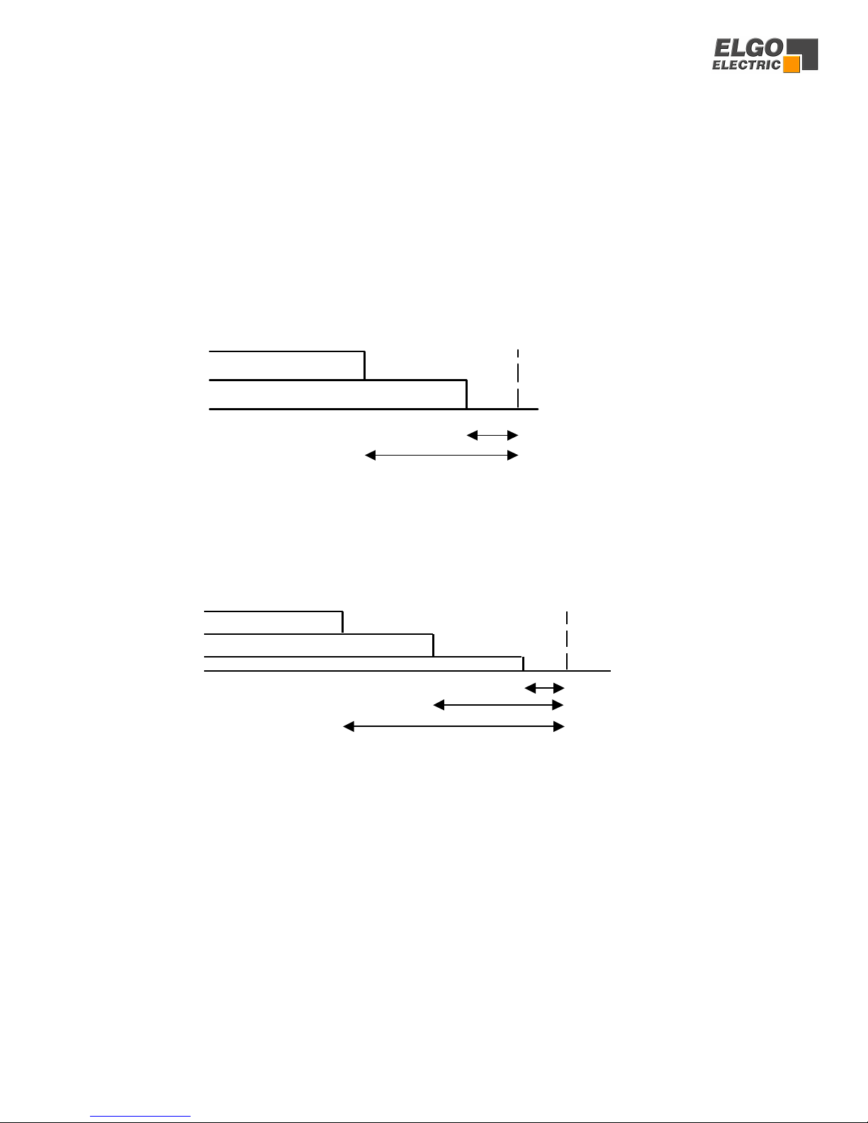
2.1 Two speed operation (switched)
NB: R1 = R2 > R3 The value in Register 1 must be the same value as R2
2.2 Three speed operation (switched)
NB: R1 > R2 > R3 The value in Register 1 must be larger than R2
Notice: The stop offset is only effective when R8 = 1xxxxx.
slow poin
t
Fast (and slow)
creep
target position
stop offset R 3
R 1
target position
fast
slow
creep
stop offset
slow point
creep point
R 3
R 2
R 1

6
2.3 Option PID-analog +/- 10 V output (regulated)
(see pages 32/33 for full description)
The setting is effected using Registers R50 to R66
2.4 Setting Datum/Reference
Datum can be set in a variety of ways. The method is selected in Register R8/3
R8 = xx0xxx Datum to R7
Closing input St 3 / 4 transfers the value set in R7
into Actual Value Display
R8 = xx1xxx Setting to Preset
Closing input St 3 / 4 transfers the Demand display
value into Actual Value Display
R8 = xx2xxx Automatic reference + (positive direction)
R8 = xx3xxx Automatic reference – (negative direction)
R8 = xx4xxx Datum with keypad alone
The value of R7 is transferred to Actual Display by
accessing R7, typing in value and then pressing E.
2.4.1 Operation of Go to Datum
After switch on of unit, initiating “Start” or “Datum” will cause the axis to move in the direction
set in R8/3. The output “going to datum” St5/7 is on.
When the Axis activates the respective end limit switch, it will stop for a time as set in R10. It will
then move slowly in the opposite direction. When it comes off the limit switch, the Encoder
marker input St1/8 is enabled. When the next marker pulse is detected, the Axis stops and value
of R7 is loaded into actual value display. The going to datum output is now turned off.
The speeds for going to Datum are set as follows:;
1. Analog control
First phase (from start to hitting end limit)
Speed set in R67 (rpm)
Second phase (from reversal to marker pulse)
Speed set in R68 (rpm)
2. Switched speed control
First phase (from start to hitting end limit)
Speed set in R69
For Creep speed R69 = xxxxx0
For Slow speed R69 = xxxxx1
For Fast speed R69 = xxxxx2
Second phase (from reversal to marker pulse)
Speed is always equal to Creep speed

7
2.6 Encoder monitoring
If after positioning is activated, no Encoder pulses are received after a time set in R19 (0.1 to 9.9
sec), positioning will be aborted and fault 01 will be displayed. Setting R19 to 0.0 sec, disables this
feature.
2.7 Batch counter
Register R18/6 sets the method of counting whether adding or subtracting
R18 = xxxxx0 No Quantity counter
R18 = xxxxx1 Automatic subtracting
R18 = xxxxx2 Automatic adding
R18 = xxxxx3 Manual subtracting
R18 = xxxxx4 Manual adding
R18 = xxxxx5 Automatic add/subtract
R18 = xxxxx6 Manual add/subtract
R18 = xxxxx7 Automatic subtracting, STOP when “zero”
R18 = xxxxx8 Manual subtracting, STOP when “zero”
With adding function, the counter starts from zero. When the set quantity is reached, the quantity
complete output will be pulsed. With subtracting function, counting from pre-set to zero takes
place. When zero is reached, the quantity complete output will be pulsed.
With add/subtract function, subtracting will take place if a pre-set value is entered. On reaching
zero, adding will ensue. The quantity complete output will still be pulsed at zero count.
2.8 Program counter
The program counter will be active when R46 > 0.
R 47 will be incremented after a complete program-operation. If R47 >= R46, a message „Count“
is shown in the actual-value-window (after program-operation) and the counting value (R47) is
shown in the Target-value-window.
Simultaneously with this message the output ST5Pin8 will be activated. If R48 = 0 the output
works “static”. If R48 > 0 the output will be reset after selected pulse-time in R48. The message
(display and output ST5Pin8 ) will be cleared after pressing any key (also when time in R48 not
ran off). In R47, the counter value can be deleted respective set to a new value.
Parameter:
R46 PCC-Limit - releases when reached (Access always possible)
R47 PCC-Counter - value (Access always possible)
R48 PCC-Timer - for output-signal (Access protected by R98)

8
2.8.1 Auxiliary Functions
When operating in program mode, an auxiliary function can be selected on each address line.
The setting is 0 – 9. The outputs appear on St5/18 to 21, binary coded. The output is set when
the appropriate address line is selected and start given. It will remain active on until the new line
is selected and start activated. When “Program End” is reached, all Auxiliary outputs are reset.
2.9 Fault monitoring
When a fault occurs, it’s number flashes in Actual Value Display
Fault number 01 = Encoder
02 = End Limit minimum
03 = End Limit maximum
04 = Actual position < min software limit (R13) Hand
Target position < min software limit (R13) Single
05 = Actual position > max software limit (R14) Hand
Target position > max software limit (R14) Single
*07 = External stop activated or wire break
08 = Number of Program lines greater than 99
The fault message is cleared by pressing any button.
“07” also flashes if Stop on front panel is activated in middle of any move.
*Notice for 07: The external stop input must be linked before system can operate. Therefore, if
external n/c pushbutton is not fitted, then insert a permanent wire link.
9
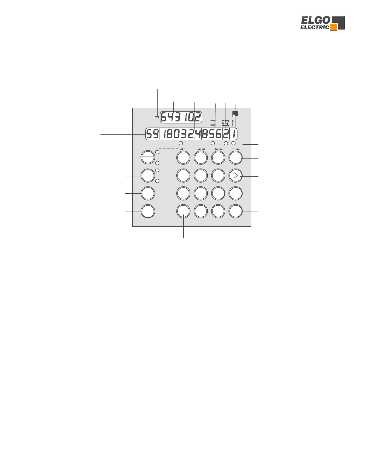
3. Front Panel
3.1 Functions of Display
Address Window : Shows address line of Program (or Register Nr)
Actual Position : Shows the Actual Position of the axis
Demand Position : Here you can enter the required position (or Register value)
Quantity Window : Shows how many pieces are left to be cut (or have been cut)
or how many incremental moves yet to be completed.
Abs/Incr Window : Defines Target window
0 = Absolute dimension
1 = Incremental + positive direction
2 = Incremental - negative direction
3 = Incremental from zero
4 = Incremental from zero – tool offset
3.2 Functions of LED’s
LED “Hand” : Illuminates after selecting “Single” mode by “Hand/Single” button
LED “Single” : Illuminates after selecting “Hand” mode by “Hand/Single” button
LED “Prog” : Illuminates when “Program” mode is selected.
LED “P-End” : Illuminates when program operation is complete (program end)
LED 1 - 4 : Indicate which input window is selected. Windows can be changed by button >
5
NR. mm
Prog
Start
Stop
4
Hand
Single
Prog
P-End
OUT
1 -
4
2-
1+
0
ELECTRIC
ELGO
>>>>
6
3
T
E
R
Hand
Single 89NR7
1
C
2
0
TYP P8721
()
sign symbol
demand
position
actual
position Quantity
absolute/in
cremental
selection
Auxiliary function
Select single / manual
Select programme
operation
Start positioning
Stop positioning
LED 1-4
Address number selector
Cursor
Set programme end
Selector for parameter
Clear Reset
Adress

10
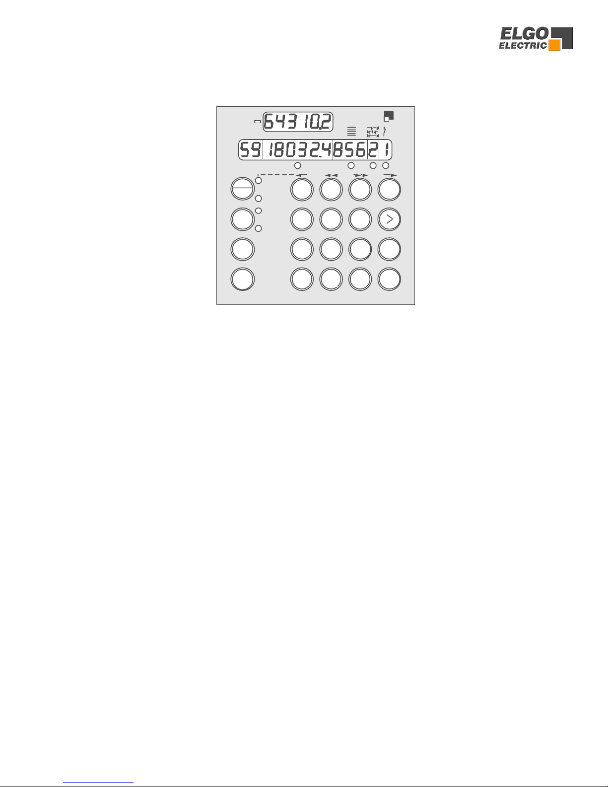
3.3 Function of the Keypad
Hand/Single
1. Alternate pressing will select “Single”.
A Demand position can be entered. Using Cursor > Button enables quantity to also be set.
2. Alternate pressing will select “Hand”.
The Buttons 7/8/9/NR can be used for manual positioning at fast and creep
speeds in both directions.
Prog Selects Program mode.
Execute the desired program by pressing “Start”.
(or Press R, to access Registers)
Start Starts positioning action
The Start Button is inhibited when programming or setting of Registers
is selected – also in Hand mode.
Stop Motion is stopped.
NR This Button is only active in Program mode. It has the following functions.
1. Start the programming action. Thereafter, only the Cursor Button > needs pressing
2. Checks existing program. Pressing “NR” repeatedly scrolls through the program.
3. Selects the required address in Table mode (see section 4.3).
5
NR. mm
Prog
Start
Stop
4
Hand
Single
Prog
P-End
OUT
1 -
4
2-
1+
0
ELECTRIC
ELGO
>>>>
6
3
T
E
R
Hand
Single 89NR7
1
C
2
0
TYP P8721
()
11
>The Cursor Button selects the Target windows sequentially.
On completion of a line, the next press of “>” will select the next Address line.
LEDs 1 – 4 indicate the selected Window.
EThis Button will :
• Set the end of program and reset the controller into operation mode.
This Button should be pressed only when the last window is selected (LED3)
• Stop the entered Register values.
• End Register setting at any point.
RSelector for entry of Register values. Only active when “Prog” selected.
TReset Button : Resets all Target windows to zero in Program mode.
CClears selected Target window value.
0 – 9 Numerical keys for data entry.
5
NR. mm
Prog
Start
Stop
4
Hand
Single
Prog
P-End
OUT
1 -
4
2-
1+
0
ELECTRIC
ELGO
>>>>
6
3
T
E
R
Hand
Single 89NR7
1
C
2
0
TYP P8721
()

12
4. Controller in Operation
Switch on conditions: On switch on, the controller assumes the same conditions as at time of
switch off. The Actual position is memorised.
In “Hand” and “Prog”, the Target windows are set to zero.
In “Single” the Demand value is made to equal Actual value.
When automatic datum routine feature is selected,R8/3 = 2 or 3 the controller will not operate,
until the datum routine has been carried out.
4.1 Single set operation
In addition to Program operation, a Single dimension can be set.
In Single operation, only an Absolute dimension and quantity can be entered. The Windows
“Abs/Incr” and “Aux” are inactive.
Press Hand/Single Till LED “Single” is illuminated alone.
Use Keys 0 – 9 To enter desired position.
Press > LED under Quantity Window illuminates.
Use Keys 0 – 9To enter desired quantity.
Press > LED under Target window illuminates.
Press Start The Axis moves to required position.
Enter new Position and Quantity and start as required.
4.2 Program Operation (R8/4 = 0)
4.2.1 Selection of a Program Block
The P8721 has a Program memory of 200 Address lines. These can be divided into several Blocks
of equal quantity of lines (see Register R41). Each Block can store a different Program, which
can be selected for operation, at will. If for example, 8 Blocks of 25 Lines is set, selecting a Block
higher than 8, will result in Block 8 being selected.
To select the required Block for operation.
Press Prog Selects Program mode
Press R The Nr (Address) Window flashes.
Key in 40 40 appears in Nr Window (flashing).
Press > The previously selected Program Block is displayed in Target window.
Press C Clears value to zero.
Key in (say) 3 3 appears in Target window.
Press E Program Block 3 is called up and sequence is ended.
controller returns to Operation mode.
Now the Block can be used with the existing program, or a new program can be entered.

13
4.2.2 Enter a program
The required Program Block is selected in accordance with section 4.2.1.
Press Prog Selects Program mode
Press Nr “01” appears in Nr Window.
ÆLED illuminates under Target window.
Press C Clears existing value.
Use Keys 0 – 9 To enter new dimension.
Press > LED illuminates under Quantity Window.
Press C Clears existing value.
Use Keys 0 – 9 To enter required quantity.
Press > LED illuminates under Abs/Incr Window
Press C Clears existing value.
Press : 0 Absolute Position
Incremental move in positive direction
ÆIncremental move in negative direction
Press > LED illuminates under Auxiliary window
Press C Clears existing value
Use Keys 0 – 9 to enter required function (i.e. 10 max)
One line of program is now complete. The Operator can now end programming or continue to
next Address line.
To end programming - Press E
To move to next line - Press >
4.3 Table operation mode (R8/4 =1)
If R8/4 is set to 1, then the Controller operates in 99 selectable address Table mode.
Programming is exactly the same as in 4.2.2.
4.3.1 Operation in Table mode
An address line of the stored program can be called up and positioning effected to that setting.
Press Prog Selects Program mode
Press T Resets Controller.
Press Nr The Nr Window flashes “0”.
Key in (say) 58 “58” flashes in Nr Window.
Press > The programmed values of address 58 are displayed.
Press Start The Axis executes the demanded settings.

14
4.4 Manual operation
Press T Resets target windows to zero
Use the Button “Hand/Single” to select “Hand”. LED “Hand” illuminates.
Buttons 7/8/9/NR can be used to move the axis forward and backwards at high and low
speeds (whilst the button is depressed). The remaining buttons are inhibited in manual mode.
The Buttons have the following functions :
Button 7Slow Reverse
Button 8Fast Reverse
Button 9Fast Forwards
Button NR Slow Forwards
If a 3 speed drive is used, the Fast and Creep speeds are used. Physical direction of movement
can be reversed by setting of Register R64.
When operating in switched speed mode ( i.e. without Analog output) the outputs
Fast/Slow/Creep/Reverse are set according to the button pressed.
When closed loop analog control is used, the respective speeds are set in R60-63 in rpm. The
proportional analog output voltage is given when the button is pressed.
5. Register Input
5.1 Unlocking Registers by Security Code
The values of Registers R1 to R97 can be changed after the Security Code 250565
has been entered into Register R98. (Note that Register R40/R6/R7 are accessible without the
need for the security-code). Accessing Registers can only take place when the Controller is in
Program Mode. In Register input mode, the decimal point is extinguished. All Registers are
entered in the target position window.
Use Button Eto : a) Store Register values b) End editing
Press Prog Controller is set to Program mode. LED “Prog” illuminates.
Press R The Nr Window flashes
Press C Clears display to zero.
Key in “98” Value 98 appears in Nr Window with “8” flashing.
Press > The Target window shows “000000” without decimal point.
Press C Clears display to zero.
Key in “250565” Display shows 250565 (The Security Code).
Press E The Controller is now set to data entry mode. All Windows are
set to zero. Decimal point is reinstated.

15
5.2 Setting and Changing Register Values
Example: The Slowdown Point of 20.0 mm needs to be entered.
Assuming that Registers have been unlocked as above :
Press R The Nr Window flashes.
Press C Clears display to zero.
Press 1 1 (flashing) is displayed in Nr Window i.e. Register 01.
Press > The existing value of R01 is displayed in Target window
decimal point is extinguished.
Press C Clears old value to zero.
Key in “200” Window shows 200 (i.e. 20.0 mm).
Press EThe new value is memorised. All Windows are reset to
zero and decimal point is reinstated.
Any Register from 1 to 97 can be selected and changed in the above manner. If sequential
Registers are to be set, Press > twice instead of E and continue editing Register by Register.
Press E on completion.
It is possible to run the Controller with Registers unlocked, e.g. having set the Stop offset
Register R03, you may now execute a “Single” move and then go back to edit R03.
5.3 Locking of Registers
Once all the values have been set, it is necessary to relock the Registers to avoid accidental
changes. There are two methods to do so.
a) Use Security Code
Press R
Key in 98
Press > 000000 is displayed
Press C Locks Registers
Press E
b) Switch off Controller.

16
6. Register List (Registers signed as * can be changed without security code)
No. Function Range Default setting Customers setting
R 1 Slow speed distance 0.1 mm 200
R 2 Creep speed distance 0.1 mm 100
R 3 Stop offset 0.1 mm 0
R 4 Backlash compensation 0.1 mm 50
R 5 Retract distance 0.1 mm 500
R 6 * Tool Width 0.1 mm 0
R 7 Datum/reference value 0.1 m 1000
R 8 System Register 1 See page 18 100000
R 9 Position reached pulse 0.1 s 10
R 10 Backlash dwell time 0.1 s 10
R 11 Quantity reached pulse 0.1 s 10
R 12 Tolerance window 0.1 mm 0
R 13 Min software limit 0.1 mm 0
R 14 Max software limit 0.1 mm 500000
R 15 Software limit selection See page 23 0
R 17 Display brightness 0-15 10
R 18 System Register 2 See page 24 0
R 19 Encoder pulse monitor time 0.1 s 0
R 20 Decimal point See page 25 0
R 21 Slow speed distance (backwards only) 0,1 mm 200
R 22 Creep speed distance (backwards only) 0,1 mm 100
R 23 Stop offset (backwards only) 0,1 mm 0
R 24 Forced loop range window 0.1 mm 0
R 25 Fixed Position 0.1 mm 1000
R 28 System Register 3 See page 26 0
R 29 Time delay for Drive inhibit 0,1 sec 10
R 30 Program end pulse 0,1 sec 10
R 31 Closed loop inhibit time in Hand 0,1 sec 10
R 33 Controller switch on condition 0,1 sec 0
R 34 Start time delay time 0,1 sec 0
R 40* Program Block selection See page 12 0
R 41 Number of lines in Prog Block 1-99 20
R 46 Program counter Limit 1-99 0
R 47 Program cycle counter 0 - 9999 0
R 48 Pulse time for program counter output 0.1 sec 0
R 50 Speed UPM 1-10000 2000
R 51 Acceleration/Deceleration revs/sec2 30
R 52 P term 1-3000 20
R 53 I term 1-1000 1
R 54 D term 1-1000 1
R 55 I limit 1-1000 1
R 56 Encoder edge multiplier 1,2,4 4
R 57 Encoder pulses per rev 1-10000 250
R 58 Stop-ramp selection 1-3 213222
R 60 Speed back hand slow Rpm 100
R 61 Speed back hand fast Rpm 1000
R 62 Speed forward hand fast Rpm 1000
R 63 Speed forward hand slow Rpm 100
R 64 Direction of manual buttons 0.1 0
R 65 Speed to fixed position Rpm 500
R 66 Acceleration for fixed position revs/sec2 5
R 67 Speed datum sequence phase 1 Rpm 100
R 68 Speed datum sequence phase 2 Rpm 10
R 69 Speed datum sequence with relays phase 1 0,1,2 0
R 88 System Register 4 See page 30 0
R 90 Button enable in service mode 0,1,2 0
R 94 Inch / factor multiplier 0.0… 9.99999 100000
R 96 Pulse scaling factor 0.00001… 9.99999 0.0… 9.99999 100000
R 97 Inch / mm selection 0, 1, 2, 3 0
R 98 Security code 250565 -
R 99 Service, see chapter 14. - - -
Logical sequence values such as these must always be present, regardless whether 3 speed, 2 speed or 1 speed drive is used.
R1 > R2 > R3 for 3 s
p
eed drive R1 = R2 > R3 for 2 s
p
eed or 1 s
p
eed drive.

17
7. Description of Registers
R1 - Slow speed distance
Distance to demand position at which the controller switches from high speed to slow speed. The output
high speed will be switched off.
R2 - Creep speed distance
Distance to demand position at which the controller switches from slow to creep speed
R3 - Stop offset distance
The over run distance can be programmed to compensate for distance from the switch-off point of the
motor to standstill. For exact positioning, the over run distance should be very small (0.0 to 0.5 mm).
Therefore the mechanical friction should be steady and the creep speed should be very slow.
During commissioning, first set R12 to zero (to eliminate Tolerance window blanking),
then set the value of R03 to 0.0 and execute a number of moves in both directions. Note
the average overrun distance and then set R03 to that value. Then set R12 to suit.
Notice: Stop offset is only functional when R8/1 = 1
R4 - Backlash overrun
To correct for screw or pinion backlash, the Demand position should be approached from one direction
only. In positive direction therefore, the Demand position will be overrun by the value of R4 and driven
back at creep speed after a time delay of R10, to the Demand position.
R5 - Retract distance
There are different modes available in the P8721, selectable by Register R18/2.
If R18/2 = 0 Retract Position = Actual + R5
If R18/2 = 1 Retract Position = Value of R5
Whilst the input St3/8 is held on, the slide will move to the “Retract” position. On release of input, slide
will return to the original position. (Value 0)
When input St3/8 is activated, the slide moves to position as set in R5 but will not return to original
position on release of input. (Value 1)
R6 - Tool offset compensation
This Register can be accessed without Security Code. When moving in incremental, it is often the case
that the subsequent function is a cut that removes part of the material. Thus to cut the correct pre-set
lengths, it is necessary to move the demanded distance plus the “Tool Offset”. This feature is active in
incremental mode only.
R7 - Datum/Reference
This Register can be accessed without Security Code.
The Datum value is stored in this Register. The value is used in different ways, in accordance with setting
of P8/3. Input St3/8 initiates loading.

18
R8 - System Register 1
This Register sets the basic operating functions of the unit.
Target window
Spindle compensation
0 = no spindle compensation
1 = negative spindle compensation
2 = positive spindle compensation
3 = negative spindle compensation with forced loop (R24)
4 = positive spindle compensation with forced loop (R24)
5 = negative spindle compensation with backlash
6 = positive spindle compensation with backlash
Relay output configuration
0 = 3 speed operation
1 = Forwards + Backwards
2 = 2 speed Run + Reverse
3 = 2 speed separate output operation
4 = Fast only in reverse
5 = 3 speed Binary coded
6 = 3 speed operation forwards + backwards
Program Memory
0 = Program line operation mode
1 = Table operation mode
Datum/reference
0 = Datum to R7 with external pulse by key-switch
1 = Datum to the target value window with external key-switch
2 = Reference run +
3 = Reference run –
4 = Datum to R7 by key-board only
Display windows (program mode only)*
0 = All windows in use
1 = Target alone
2 = Target + Batch counter
3 = Target + Batch counter + Abs/Incr.
Type of positioning
0 = Analog positioning
1 = Fast/slow/stop mode
* Display selection for single mode see R28/6

19
7.1 Backlash positioning
Adjustable in register R8/6
R8 = XXXXX5 Backlash with negative spindle compensation
R8 = XXXXX6 Backlash with positive spindle compensation
If the actual value after positioning is inside the range of the backlash window, with next START
a new positioning (if necessary with forced loop) will be proceeded to the old target position.
Single mode = START to the target value
Program mode = No address line stepping, START to the present target value
R24 R24
R12 R12
Backl. window TARGET Backl. window
(see example below)
Backlash window:
Target = 100,0
Tolerance window R12 = 1,0
Loop window R24 = 2,0
Example:
The window range for the backlash positioning = 98,0… 99,0 and 101,0… 102,0
- If the actual value is in the range of this values, a backlash positioning will be proceeded
- If the actual value is in the range of the tolerance window 99,0 - 101,0, thus in the single mode no
START is activated. In the program line mode, it will be stepped to the next address line and
positioned to new target.
- Outside of the tolerance and backlash windows, it will be positioned to the target value (Single mode). In
the program line mode, it will be stepped to the next address line and positioned to new target.
Example of the window ranges, with above settings:
Tar
g
et Æ
ÆÆ
Æ100,0
Actual Æ
ÆÆ
Æ98,0 99,0 101,0 102,0
Backlash window Tolerance window Backlash window

20
7.2 Output configurations
These depend on setting of Register R8/5
Value 0 3 speed operation (Elgo standard default)
3 speeds selected by relays 1,2 & 3
output 4 sets direction reverse
OUTPUT ST5/ 1 2 3 4
Creep forwards X
Slow forwards X X
Fast forwards X X X
Creep reverse X X
Slow reverse X X X
Fast reverse X X X X
R1 = Run, R2 = Slow & R3 = Fast combined with Run.
If used with 2 speed, R2 or R3 = Fast.
Can also be used with single speed.
Value 1 2 speed operation
Independent outputs forward and reverse
Independent outputs fast and slow
OUTPUT ST5/ 1 2 3 4
Creep forwards X X
Slow forwards
Fast forwards X X
Creep reverse X X
Slow reverse
Fast reverse X X
R1 = Run forwards, R4 = Run reverse, R2 = Creep, R3 = Fast
Value 2 2 speed operation
Speed set by Relays 2 & 3
Direction set by Relay 4
OUTPUT ST5/ 1 2 3 4
Creep forwards X X
Slow forwards
Fast forwards X X
Creep reverse X X X
Slow reverse
Fast reverse X X X
R1 = Positioning (drive inhibit or brake)
R2 = Creep, R3 = Fast (both independent)
Other manuals for SERIES P8721-000-P
1
Table of contents
Other ELGO Electric Controllers manuals


