manuals.online logo
Brands
  1. Home
  2. •
  3. Brands
  4. •
  5. BZ PRODUCTS
  6. •
  7. Controllers
  8. •
  9. BZ PRODUCTS BZ 7/12 User manual

BZ PRODUCTS BZ 7/12 User manual

BZ PRODUCTS, INC.
INSTALLATION MANUAL
VERSION 1.0
MODEL BZ 7/12
BZ 7/24
BZ 7/36
BZ 7/48
PWM SOLAR CHARGE CONTROL
CAUTION! READ ALL INSTRUCTIONS PRIOR TO
INSTALLING OR USING THIS EQUIPMENT.
SAFETY INSTRUCTIONS:
Refer service to qualified service personal. Incorrect installation may result in risk
of fire. Remove all sources of electrical power, photovoltaic and battery before servicing
this equipment. Never charge a frozen battery. Warning batteries produce explosive
gasses during normal operation. Install batteries in a well ventilated location. Follow
battery manufactures maintenance and operational recommendations. Install properly
rated fuses.
MISWIRING THE BZ 7 WILL DAMAGE THE CONTROLLER AND VOID THE WARRANTY
DESCRIPTION: The BZ 7 PWM charge controller is a high efficiency, shunt type charge controller
capable of charge currents of 7 amps. Features include a low loss Schotkey diode to prevent night time
battery discharge, easily adjusted float voltage, MOV lightning protection, battery voltage temperature
compensation, float LED, easy installation, epoxy potted and five year limited warranty. Made in USA
SYSTEM LAYOUT: Plan your installation. Install the BZ 7 near the battery bank. Avoid installing the
controller in wet, damp or confined locations. Do not install the BZ 7 in direct sunlight. Use short direct
wiring to the controller, batteries and PV panels. Install the controller in accordance with all state, local and
national electrical codes. Securely fasten the controller to a wall or other suitable structure. Provide support
for all wiring. Provide proper ventilation for the batteries.
WIRE AND WIRING: Use high quality stranded wire in all installations. Solid wire is not
recommended. Use #10 or #12 wire to wire the PV panels and batteries. Protect wire from damage.
Carefully plan the installation. Clearly labeling all wiring will simplify installation and help prevent wiring
errors. Permanent wire markers are recommended for labeling all wiring. Rout wiring as directly as
possible to the PV panels and battery. Take care to follow the wiring diagram exactly. Properly seal all
wiring against water leaks. Provide proper ventilation for the batteries.
CAUTION DISCONNECT ALL SOURCES OF ELECTRICAL POWER BEFORE CHANGING FUSES.
FUSES: Install a 10 amp fuse and fuse holder in the Battery + wire within 9” of the Battery + terminal.
Install a 10 amp fuse and fuse holder in the PV + wire. See wiring diagram for details. Warranty is void if
no fuses are installed.
OPERATION: Operation of the BZ 7 is fully automatic. When the battery voltage is lower than the float
voltage, full PV charge current is applied to the battery. When the battery voltage equals the float voltage
the BZ 7’s PWM circuitry activates and maintains the float voltage. During PWM operation battery charge
current will diminish. The PV array voltage will vary greatly during normal operation.
DURING OPERATION THE BZ 7 MAY FEEL WARM.
THE BZ 7 FLOAT VOLTAGE IS PRE-CALIBRATED.
NO ADJUSTMENT IS NEEDED WHEN USING WET LEAD ACID BATTERIES.
FLOAT VOLTAGE CALIBRATION: (Twelve volt nominal system. Refer to specifications for float
voltage set points for 24, 36 and 48 volt systems). Battery float voltage is the voltage that the BZ 7 allows
the battery to charge up to and not exceeded. Battery float voltage is pre-calibrated to 14. 1 volts.
In most installations the float voltage needs no adjustment. Check battery manufactures
recommendations for proper charge voltage.
Do not attempt to adjust the float voltage on cloudy or overcast days. To properly adjust the battery float
voltage a Digital Volt Meter is required. Locate the float voltage adjustment control, refer to the wiring
diagram. Connect the Digital Volt Meter to the battery. A 1/8” wide screw driver is needed to adjust the
float voltage. Adjust the float voltage control in small increments, turning the float voltage control clock
wise to increases the float voltage and counter clockwise to lower the float voltage, until the desired float
voltage is displayed on the Digital Volt Meter. The YELLOW Float LED will light when the float voltage
is reached. Disconnect the Digital Volt Meter from the battery.
MAINTENANCE: The BZ 7 requires little maintenance. Periodically clean the BZ 7 with a damp cloth.
Inspect all wire and wire connections. Tighten and clean all connections as required. Recalibrate float
voltage if required. Visually inspect the entire PV system for damage. Keep the PV array clean and
properly aligned. Keep batteries clean. Follow battery manufactures maintenance recommendations.
WARRANTY: BZ Products, INC. Model BZ 7 is warranted to be free of defects in material and
workmanship for five years from the date of purchase. Failure to provide correct installation, operation or
care for this product, in accordance with this instruction manual, will void the warranty. Product liability
shall be limited to repair or replacement, at the discretion of the manufacture. The manufacture is not
responsible for the labor or other charges necessitated by the removal, transportation, or reinstallation of
any defective product. Warranty does not cover damage due to, mishandling, abusive conditions, lightning,
or exposure to weather. No specific claim of merchantability shall be assumed or implied beyond what is
printed in this manual. No liability shall exist from circumstances arising from the inability to use this
product, or it’s inappropriateness for any specific purpose. In all cases, it shall be the responsibility of the
customer to insure a safe installation in compliance with local, state and national electrical codes.
RETURN PROCEDURE: To return a model BZ 7 for repair provide the following information.
Name/Company name, return address, daytime phone number, description of failure, copy of sales receipt.
Include $7.00 for return postage. Return to BZ Products, INC.
BZ PRODUCTS, INC.
7614 MARION Ct. St. LOUIS MO 63143 USA (314) 644-2490 [email protected]
SPECIFICATIONS:
PV charge current 7 amps continuous Surge current 10 amps 15 min
Array voltage 12 Volts 30 volts open circuit Control PWM shunt control
Array voltage 24 Volts 60 volts open circuit Voltage drop < 0.5 volts @ 7 amps
Array voltage 36 Volts 80 volts open circuit Temp. Comp. -18mV/°C
Array voltage 48 Volts 100 volts open circuit Battery size 120 amp hour min
Float voltage range 12 to 15 volts Float voltage 14.1 VDC (12 volt nom)
Float voltage range 25 to 31 volts Float voltage 28.2 VDC (24 volt nom)
Float voltage range 37 to 45 volts Float voltage 42.3 VDC (36 volt nom)
Float voltage range 48 to 60 volts Float voltage 56.4 VDC (48 volt nom)
Operating current .02 amps nominalFloat regulation ± .05 volts nominal
Wire size # 16 AWG Wire length 18” stranded
Reverse current .01 amps nominalSize 4” X 3.5” X 1”
Operating temp. -30 to + 50°C Storage temp. -30 to + 70°C
Lightning Protection 10MM MOV Wight 8 ounces
Specifications subject to change without notice. Made in USA 1/05

This manual suits for next models

3

Other BZ PRODUCTS Controllers manuals

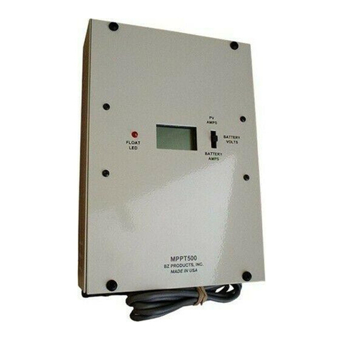
BZ PRODUCTS MPPT500 User manual

BZ PRODUCTS

BZ PRODUCTS MPPT500 User manual

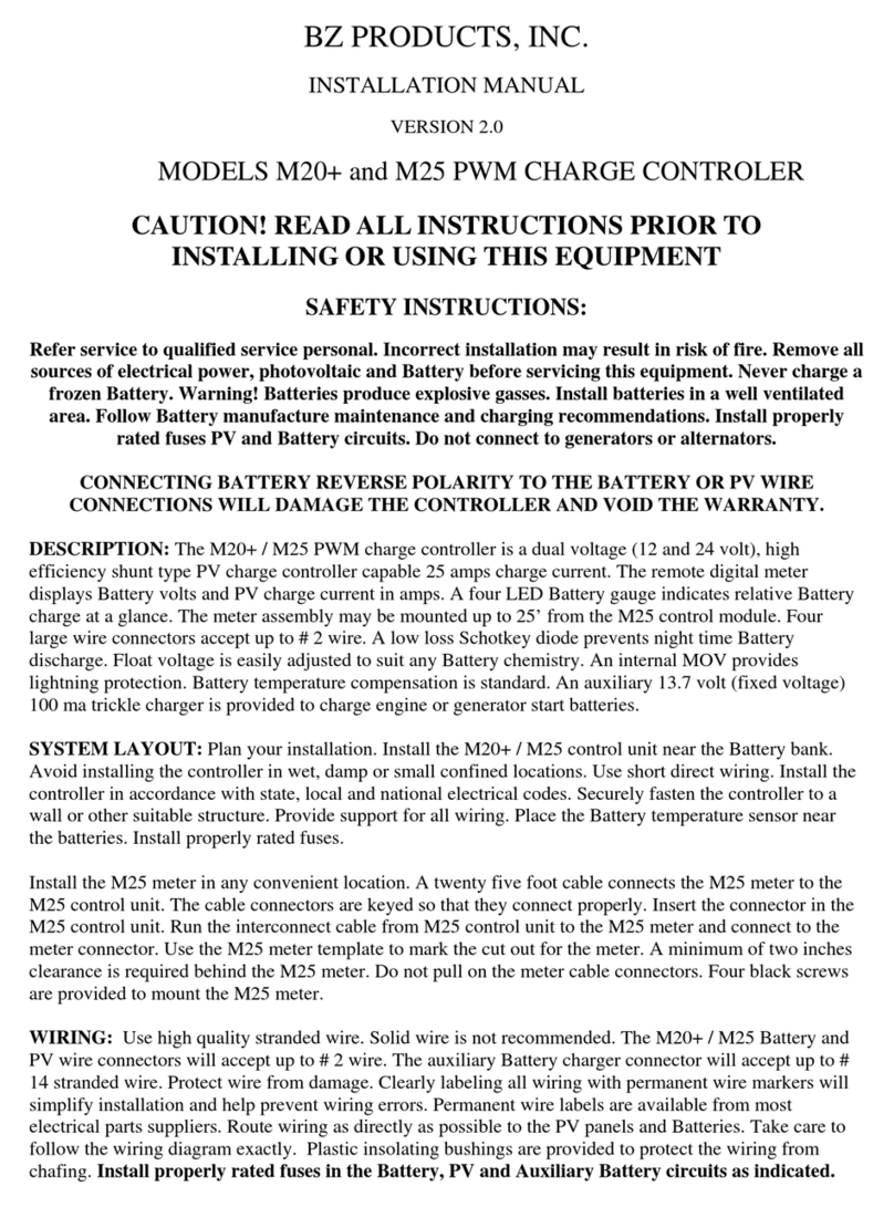
BZ PRODUCTS M20+ User manual

BZ PRODUCTS

BZ PRODUCTS M20+ User manual

BZ PRODUCTS MPPT250 User manual

BZ PRODUCTS

BZ PRODUCTS MPPT250 User manual

Popular Controllers manuals by other brands

Airflow Uno hab Installation and operating instructions

Airflow

Airflow Uno hab Installation and operating instructions

Eliwell ID 985 LX manual

Eliwell

Eliwell ID 985 LX manual

SOMFY Animeo IB+ installation guide

SOMFY

SOMFY Animeo IB+ installation guide

WebDT WebDT 133 manual

WebDT

WebDT WebDT 133 manual

Emerson Fisher 1066 instruction manual

Emerson

Emerson Fisher 1066 instruction manual

ABB i-bus SA/S 2.6.2.1 product manual

ABB

ABB i-bus SA/S 2.6.2.1 product manual

Philips 9290 014 61062 installation guide

Philips

Philips 9290 014 61062 installation guide

American Standard Gold 824 user guide

American Standard

American Standard Gold 824 user guide

IBM MTM 2145-SV1 Hardware installation guide

IBM

IBM MTM 2145-SV1 Hardware installation guide

CVS Controls 67AFR product manual

CVS Controls

CVS Controls 67AFR product manual

Agromehanika AG-TRONIK S1 Instructions for use

Agromehanika

Agromehanika AG-TRONIK S1 Instructions for use

Dynamite DYNM3865 instruction manual

Dynamite

Dynamite DYNM3865 instruction manual

Adaptec GDT8546RZ - ICP Vortex RAID Controller Installation and user guide

Adaptec

Adaptec GDT8546RZ - ICP Vortex RAID Controller Installation and user guide

Omron SYSMAC C200H-FZ001 Operation manual

Omron

Omron SYSMAC C200H-FZ001 Operation manual

Evco EVJ 200 quick start guide

Evco

Evco EVJ 200 quick start guide

Aspira S-0241.02 manual

Aspira

Aspira S-0241.02 manual

SUPMEA U-SUP-EC8.0-EN2 user manual

SUPMEA

SUPMEA U-SUP-EC8.0-EN2 user manual

Mitsubishi AL2 Series Programming manual

Mitsubishi

Mitsubishi AL2 Series Programming manual

manuals.online logo
manuals.online logoBrands
  • About & Mission
  • Contact us
  • Privacy Policy
  • Terms and Conditions

Copyright 2025 Manuals.Online. All Rights Reserved.