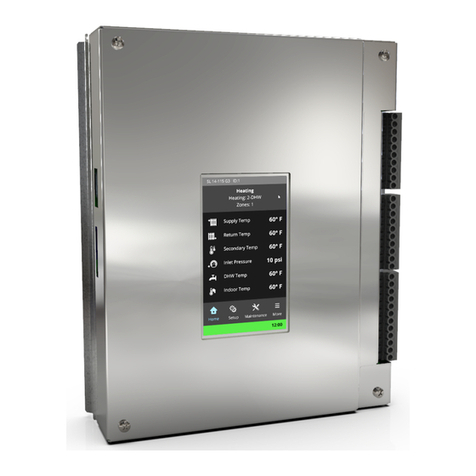
IBC V-10 User manual

OPERATING INSTRUCTIONS
www.ibcboiler.com
V-10 TOUCH SCREEN
BOILER CONTROLLER
This Manual is also available in French - contact IBC or visit our web site www.ibcboiler.com


INSTALLATION AND OPERATING INSTRUCTIONS
V-10 TOUCH SCREEN BOILER CONTROLLER
1.0 IBC MODEL V10 TOUCH SCREEN CONTROLLER ..................................1
1.1 GENERAL ...............................................................1
1.2 CONTROL ...............................................................1
1.3 CONTROL INTERFACE.....................................................2
1.3.1 BOILER STATUS BAR ................................................2
1.3.2 NAVIGATION OVERVIEW .............................................3
1.3.2.1 MENU SCREENS .............................................3
1.3.2.2 STATUS DISPLAY SCREENS....................................3
1.3.2.3 SETTING SCREENS...........................................3
1.3.2.4 PASSWORD POP-UP WINDOW .................................4
1.3.2.5 LEFT SIDE SLIDE BAR.........................................4
1.3.2.6 COMMON BUTTON ICONS .....................................4
1.4 HOME SCREEN ...........................................................5
1.5 MAIN MENU..............................................................5
1.5.1 MAIN MENU SELECTIONS ............................................5
1.5.2 EXPRESS SETUP ...................................................6
1.5.3 LOAD STATUS ......................................................7
1.5.4 USER SETUP.......................................................7
1.5.5 INSTALLER SETTINGS ...............................................8
1.5.5.1 LOAD SETTINGS ............................................8
1.5.5.2 SYSTEM SETTINGS .........................................10
1.5.6 DIAGNOSTICS.....................................................10
1.6 SEQUENCE OF OPERATION ...............................................12
1.6.1 STANDBY.........................................................13
1.6.2 PURGING.........................................................13
1.6.3 IGNITION .........................................................13
1.6.4 HEATING .........................................................14
1.6.5 CIRCULATING . . . . . . . . . . . . . . . . . . . . . . . . . . . . . . . . . . . . . . . . . . . . . . . . . . . . .14
1.6.6 ERROR MODE.....................................................15
1.7 OTHER OPERATING FEATURES............................................15
1.7.1 PRIORITY.........................................................15
1.7.2 LOAD COMBINING .................................................16
1.7.2.1 CONSIDERATIONS FOR COMBINING LOADS .....................17
1.7.3 RESET HEATING ...................................................18
1.7.4 TEMPERATURE DIFFERENTIAL SETTINGS .............................19
1.7.5 DAILY TEMPERATURE OVERRIDES . . . . . . . . . . . . . . . . . . . . . . . . . . . . . . . . . . .19
1.7.6 UNOCCUPIED MODE ...............................................20
1.7.7 SUMMER SHUTDOWN ..............................................20
1.7.8 EXTERNAL CONTROL ..............................................21
1.7.9 ALARM CONTACTS.................................................21
1.7.10 MULTI-BOILER OPERATIONS ........................................21
1.7.11 INTERNET NETWORKING ...........................................22
1.7.12 WEB BROWSER INTERFACE.........................................23
1.7.13 BACnet SUPPORT..................................................23
2.0 DIAGRAMS .................................................................24
2.1 ELECTRICAL WIRING DIAGRAM ............................................24
2.2 INTERNAL WIRING DIAGRAM ..............................................26
2.3 CONTROLLER BOARD LAYOUT ............................................27
2.4 SEQUENCE OF OPERATION ...............................................28
CONTENTS


1
OPERATING INSTRUCTIONS
V-10 TOUCH SCREEN BOILER CONTROLLER
GENERAL
The IBC V-10 Boiler Controller is available for all VFC and SL series condensing
boilers. The touch screen controller is engineered to be backward compatible
with previous IBC 5 button boiler controllers.
The controller is equipped to provide:
• Control of up to 5 pumps – 1 boiler pump + 4 separate load pumps
• Outdoor Reset control
• Set Point temperature regulation
• Domestic Hot Water (DHW)
• External control via 0-10VDC or 4-20mA signaling
• Alarm dry contacts
•
Load Combining – simultaneous operation of 2 similar water temperature loads
• The control can manage and/or operate in a network of up to 24 IBC VFC or
SL boilers
Some of the new features available in the touch screen control include:
• Express Setup Menu for simple, quick programing
• Software updatable in the eld with a SD card or a USB stick
• Setup conguration back-up and cloning using SD card or USB stick
• Superior warning messages while setting up the control
• Advanced Error messages with visual display on the Home Screen
• Internet/LAN connectivity
• BACnet (with activation)
CONTROL
When the boiler is rst energized, the controller will go through a power up
sequence that will take approximately 90 seconds. During this time the controller
is completing a self-diagnostic and loading all previous settings. In the event of a
power interruption the boiler will automatically resume operation when power is
restored with all the previously stored values.
The controller provides overall management of the boiler operations including;
• Power-up, self-diagnostics, easy load parameter adjustments
• Burner operation, safety management systems, call for heat management and
load priority
• Real time boiler data
• Temperature and throttle operation
• Maintenance of operational and error service logs
• 2-way communication between other IBC boilers and controls
IBC MODEL V-10 TOUCH
SCREEN BOILER CONTROLLER
1.0
1.0
1.2
NOTE
To view the software version
on the controller go to Main
Menu, Diagnostics, Boiler
Information.

OPERATING INSTRUCTIONS
2
V-10 TOUCH SCREEN BOILER CONTROLLER
Operational and historical data may be accessed at any time using the System
Status and Load Proles sections of the control. Error logs are available in the
Diagnostics section and the controller is capable of recording any or all errors
since original power-up complete with the date and time of the error.
CONTROL INTERFACE
This section explains the general structure of the control interface and,
• how to navigate through the screens
• how to display information
• how to enter settings
The specic purpose and effect on boiler operation of the various parameters that
can be displayed and adjusted will be explained later in this manual.
The control interface is provided through a 2-1/4 x 4 inch, colour Touch Screen
display. The Touch Screen responds to a light nger touch on the screen. You
can also use a stylus or similar device to operate the touch controls. Do not use
a sharp or metallic object such as a screw driver to operate the control as it could
damage the touch screen.
The controller display is divided into two areas, the screen active area and the
boiler status bar. All screens have an active area consisting of the screen title bar
at the top and a boarder surrounding the active area. At the bottom of the display
there is space reserved for the boiler status bar.
Prior to any interaction with the touch screen the display will be showing the
Home screen that includes details of the current boiler status. If the controller
has been left on the Home screen long enough (user adjustable, 10 minutes by
default) the display with be dimmed to save power.
The control will automatically return to the home screen if left unattended.
The screens will step back one screen at a time in 10 minute increments if the
touch screen has not been touched. The pop-up windows will also step back
automatically in 2 minute intervals.
1.3.1 Boiler Status Bar
The boiler status bar indicates if the boiler is in a normal, warning or alarm
state. When no warning or alarm state is present, the bar will be green and the
time will be displayed inside the green area. The bar can also be yellow or red
corresponding a warning or alarm state. Text inside the bar will indicate the
specic warning or alarm present. If more than one alarm is present the text
display will slowly change, rotating though whatever alarms that are present.
CAUTION
No sharp or metallic object
should be used on the touch
screen as this will cause
damage. Use only a Stylus or
your clean nger
1.3
Status Bar Graphics

3
OPERATING INSTRUCTIONS
V-10 TOUCH SCREEN BOILER CONTROLLER
1.3.2 Navigation Overview
Navigating through the controller touch screen interface is designed to be simple,
consistent and intuitive.
There are three screen types; Menu Screens, Status Display Screens and
Setting Screens. The display can be split in some cases to show a Menu Screen
and a Setting Screen at the same time.
1.3.2.1 MENU SCREENS
Menu screens are a list of choices that lead to other screens. The screen
is divided into evenly spaced button icons each labeled with a choice to be
selected. At the bottom of the active screen will be a Back button to return to the
previous page.
1.3.2.2 STATUS DISPLAY SCREENS
These screens are self-explanatory. Text describing various parameters is listed
along with the current value for each. Data cannot be entered or values changed
on these screens. If there are no buttons on the screen, touching the screen
anywhere in the active area will exit the screen.
1.3.2.3 SETTING SCREENS
A Setting Screen presents various parameters and setting options to allow new
values to be entered and saved as necessary.
There are four ways new settings are entered;
• an Entry Box
• an Entry Button
• a Radio Button
• a Check Box
An entry box is used in most cases to adjust parameter settings. Entry buttons
are used to set the load type. Radio buttons are used to select a setting from a
list of options and can be used in conjunction with entry boxes. A check box is
used to select whether a specic function or capability is turned on or off, enabled
or disabled.
To change the value in an Entry Box or Entry Button, touch the current entry and
a pop up window will appear. If the entry type is a number, the pop-up window will
show a numeric keypad with the current entry value displayed above it. Touching the
numbers on the keypad will change the value displayed. The back arrow button will
delete the last digit entered. If the value is not numeric the popup window will show a
list of options to choose from with a radio button adjacent to each choice. Select the
option required by touching it and the radio button will light indicating the selection.
At the bottom of the pop-up window will be an OK button and a Cancel button.
Pressing the OK button accepts the value or selection displayed and closes the pop-
up window displaying the new value in the entry box. The Cancel button disregards
any value changed and closes the pop-up window, making no adjustments.
Any changes entered will be displayed on the settings screen for review. The
Save button at the bottom of the settings screen must be pressed for the
changes to implemented. NOTE: Any changes entered will not be saved
unless the Save button is pressed.
Entry Box
Entry Button
Check Box
Numeric Key Pad
Radio Buttons

OPERATING INSTRUCTIONS
4
V-10 TOUCH SCREEN BOILER CONTROLLER
1.3.2.4 PASSWORD POP-UP WINDOW
Access to setup areas that allow operational parameters to be changed can be
restricted by requiring a password to be entered. If the Security mode is on then
the password pop-up window with will appear as soon as a button is pressed that
provides access to a restricted area. The password is factory set and cannot be
changed.
The password window shows 4 digits with an up arrow and down arrow
button above and below the digit. The password graphic looks similar to some
combinations locks. Touching the arrow button above or below the digit will cause
the digit to increment up or down respectively. Tap the appropriate buttons until
the desired password is displayed. Pressing OK will close the popup and then
grant access. Access to secure areas will remain available for 15 minutes without
having to reenter the password.
1.3.2.5 SLIDE BAR
The Slide Bar (left side) allows the viewing of a list that is longer than will t
inside the active display area. For example, while editing a load in the installer
menu, the list of items is longer than can t on one screen. Simply touch and hold
the Slide Bar until it turns blue and slowly drag it down. As you do the list of items
viewable will scroll with the side bar. You can also tap the arrows at either end of
the Slide Bar to move the bar up or down.
1.3.2.6 COMMON BUTTON ICONS
Save will save the displayed settings and return you to the previous screen. This
button is found at the bottom left on all Setting Screens.
Back will return you to the previous screen without saving any changes. This
button is found at the bottom right on all Setting Screens and all menu screens.
OK will accept the settings displayed in a pop-up window and close the window.
This button is only found at the bottom left of a pop up window.
Cancel will ignore the settings displayed in a pop-up window and close the
window. This button is only found at the bottom right of a pop-up window.
Edit is only available in the Installer Settings menu and only active on loads
that have been dened. Pressing Edit will enter the settings screen for the
corresponding load or setting.
Close appears at the bottom of a Warning pop-up window.
View is only available in the Error Log to display the particular Minor errors, Major
errors or System faults associated with the logged error event.
The single Up and Down arrow is available in the Error Log menu and enables
you to scroll through the list of event records one at a time.
The single Left and Right arrow is available in the Load Proles screen to scroll
through the 4 separate loads plus the remote load if the boiler is operating as part
of a multi boiler network.

5
OPERATING INSTRUCTIONS
V-10 TOUCH SCREEN BOILER CONTROLLER
HOME SCREEN
The Home Screen displays basic boiler status information. The title bar shows
the boiler model number and boiler ID number if set higher than zero. Just
below the title bar a line of bold text indicates the current operating state and
immediately below that the load currently being serviced, if any, is displayed.
Up to 8 of the current operating values are listed on the balance of the active
screen. If there is no current value for a given parameter, for example when no
corresponding temperature sensor is connected, then there is no line of text for
that value.
MAIN MENU
To enter the Main Menu screen simply press anywhere on the Home screen. If
the display has been dimmed you will need to touch the screen twice.
The Main Menu displays 5 possible selections allowing quick and easy
access to all areas of the controller interface. The selections support the
display of extensive operational and diagnostic information and provide a
structured interface for the adjustment of control settings. The User Setup
selection provides a relatively simple interface allowing for the adjustment of
settings relevant to the user while Installer Setup gives eld access to the full
functionality of the system for the appropriately trained heating professional.
The split access also allows a layer of security against “nger trouble”, including
accidental adjustment to settings that could lead to inefcient operation (e.g.
excessive cycling) or dangerous conditions.
1.5.1 Main Menu Selections
Express Setup gives the installer a simplied and fast way to setup and enable
any or all of the 4 Loads. This easy to use feature walks the installer through the
basic settings of the controller and sets parameters to default (typical) values
that will work for the selected load type and can be adjusted if required. Error
messages are displayed if the installer sets the values incorrectly. All Loads are
factory set to OFF allowing the installer to easily choose a type for each load
when the controller is rst powered on.
Touching Load Status will bring up a menu screen with six possible selections
to display the current status details for the 4 individual loads, operating Load
Statistics and the operational Load Proles (graphs) for each load.
1.4
1.5

OPERATING INSTRUCTIONS
6
V-10 TOUCH SCREEN BOILER CONTROLLER
User Setup leads to the User Settings screen where the installer or end user can
set the time and date, overrides, screen brightness, hot water tank temperature,
occupied status and choose Imperial or Metric units.
The Installer Setup selection gives access to all congurable settings for the
advanced installer. If security is turned on, an Enter Password window will
appear requiring the correct password to be entered before access is granted. All
4 Loads can be set to any of the available types with all possible parameters for
each load available for editing. Menu buttons provide further access to settings
for Load Combining and Multi-Boiler operation. The System Settings selection
leads to the Systems Settings menu screen where Site Settings, Network
Settings, Security, Licensing, Backup & Restore and Boiler Information are
available.
The Diagnostics menu screen includes Error Log, Temperature Sensors,
Pressure Sensors, Fan Operation, Network Information, Clean the Screen,
and Advanced Diagnostics selections. Most selections provided information
only. The Clean the Screen section allows the touch screen to be de-activated
for 60 seconds while the screen is being cleaned. Advanced Diagnostics is
where the installer can view advanced diagnostic information, do a Software
Update, Clear Error messages, Restart the boiler, Reset Factory Defaults
and calibrate the touch screen.
1.5.2 Express Setup
Express Setup is a quick and simple method to set all the necessary parameters
for most single boiler installations. Express Setup sets parameters to default
values including all the appropriate values to operate each load type under most
operating conditions. A Settings Screen will present the default values for review
and if necessary the settings can be adjusted. The controller checks entries for
compatibility and displays an error prompt to advise the installer to correct a
mistake.
Begin Express Setup by touching the Express Setup button. If the boiler has
never had any programming done previously. or if all loads are set to Off, this
will display the Express - Site Settings screen. This screen allows you to
choose Imperial or Metric units, enter the Design Outdoor Temperature, view
your altitude and set the clock. The Design Outdoor Air Temperature must be set
correctly for your geographic location if Reset Heating is to be used for any of
the loads. This temperature is available from a number of sources including the
local IBC wholesaler. The Design Outdoor Air Temperature can also be found in
the heat loss calculation documentation used in the design of the heating system.
The boiler controller is equipped to automatically detect altitude so this value will
be set for you.
The Time and Date settings can be changed by touching the Set Clock button
and entering desired settings. If the boiler is connected to the Internet then
selecting NTP Server will automatically set the time. Once the desired entries
have been made press the Save button and the display will change to the
Express – Loads menu screen.

7
OPERATING INSTRUCTIONS
V-10 TOUCH SCREEN BOILER CONTROLLER
The Express – Loads screen displays a selection button for each of the 4
possible loads. All loads are set to OFF from the factory allowing the system to
be programmed to correspond to the installation’s specic wiring connections. If
Load 1 has been piped and wired - (Load 1 = P/V1 & Therm.1) to heat something
press the Load 1 button. Next, select the type of load being heated with Load
1; Reset Heating, Setpoint, DHW (Domestic Hot Water), or External control.
If Setpoint, DHW or External Control is selected a settings screen will be shown
with the values pre-programmed appropriately for typical residential applications.
If Reset Heating is selected then the emitter type must be selected and then
the settings screen will be displayed. The pre-programmed values should be
carefully reviewed to be sure they will work for the intended application. The
values can be changed if necessary by following the methods described in
section 1.3.2.2 Setting Screens in this manual. When all the values are set as
required, press Save at the bottom of the screen to save the changes and the
Select a Load Screen will return. Pressing the Back button will return to select a
Load Screen with no load type being assigned.
These steps can be repeated for all loads connected to the boiler.
Express Setup can be used at any time after the controller has been programmed
to reset or alter the current settings of a load or to add settings for a programmed
load. Outdoor design temperature can be adjusted in the Installer Menu.
1.5.3 Load Status
Touching one of the Load 1 to 4 buttons will bring up a status display screen
listing specic operational information about that load in real time. If a sensor
is not connected to the controller, for example a DHW sensor or the Outdoor
sensor then the display will show n/c for Not Connected. Cycles/Day is a running
tally of the number of calls for heat that load has received in the last 24 hours. In
general, fewer cycles per day = better efciency and usually better comfort.
Touching the Load Statistics button will access a status screen that will list run
time statistics for the boiler including specics for each load.
Load Proles will give access to screens for each load that show a bar graph
prole of the time the boiler is ring at various throttle levels.
1.5.4 User Setup
The User Settings screen is a combination menu and settings screen. Date &
Time, Overrides and Backlight are the three available menu buttons. The water
Tank Temperature can be changed by touching the entry box. Radio buttons are
used to select the Occupied status and Units.
On the Time and Date settings screen NTP Server or Internal can be chosen.
The controller must be connected to the Internet for the NTP Server selection to
work properly. Choosing NTP Server will make the controller, when connected to
the Internet; automatically update its internal clock from an Internet time service.
If Internal is selected then the time must be set manually. The Time Zone and
Auto DST should be set appropriately in either case.

OPERATING INSTRUCTIONS
8
V-10 TOUCH SCREEN BOILER CONTROLLER
The Overrides screen allows the override programming for each load to be
enabled or disabled and by touching the Edit button the override temperatures
with corresponding start and end times can be set for each load by day of the
week. There are two override programs for each day of the week. (Refer to
section: 1.7.5)
The Backlight Settings screen provides a slide bar to set the screen backlight
level (brightness) and a Dim Time setting to control the length of time, with no touch
screen interaction, the controller waits before dimming the screen to save power.
1.5.5 Installer Settings
The Installer Settings screen gives access to all congurable settings for the
advanced installer.
There is an Entry Button for each of the 4 available loads used to assign the
load types. Once a type is assigned all the load’s parameters can be edited
independently. Setting the load type to Off means that load is disabled and will
not be used.
The Multi-Boiler, Load Combining and System Settings menu buttons
complete the selections available on the Installer Settings screen.
• Multi-Boiler provides access to settings required for the boiler to operate as
part of a multi-boiler system. (Refer to section: 1.7.10)
• Load Combining provides access to settings for required to enable the
boiler’s Load Combining (previously known as Load Pairing) feature. (Refer to
section: 1.7.2 )
• System Settings leads to a menu screen where the Site Settings, Network
Settings, Security, Licensing and Backup & Restore selections are
available.
1.5.5.1 LOAD SETTINGS
Most load settings available to adjust are self-explanatory to the experienced
installer but listed below are ones that may be new to some installers:
Boiler Pump – This feature is available for all load types and allows the installer
to have the Boiler Pump (primary loop pump) off while this load is running. The
load pump must be piped in such a way (series piping) as to ensure adequate
ow through the boiler without needing the Boiler Pump to provide ow through
the heat exchanger. When you set the Boiler Pump to Off a warning message will
appear as a reminder. If the load is a radiant oor then it is strongly recommended
to use primary/secondary piping and leave the Boiler Pump set On.
Ramp Speed – Ramp Speed allows the installer to adjust how fast the boiler
tries to raise the water temperature owing though the heat emitters. With a n
tube baseboard radiator you may want the water temperature to rise quickly to
provide heat as quickly as possible. This type of heat emitter has very little mass
so it can heat up quickly and when the call for heat is removed, cools down
quickly. A radiant oor, on the other hand, has signicant mass therefore takes a
long time to heat up. When the call for heat is removed, the oor is still warm and
will continue to add heat to the space for a signicant period of time.

9
OPERATING INSTRUCTIONS
V-10 TOUCH SCREEN BOILER CONTROLLER
Depending on the settings it’s possible for the indoor temperature to overshoot
the desired indoor temperature. Reducing the Ramp Speed Value will help
reduce this overshooting issue.
The factory Ramp Speed setting is Auto. While set to Auto the controller uses
the selected heat emitter type to automatically determine an appropriate ramp
speed. The installer can manually set the Ramp Speed by choosing a value from
1 to 10. A setting of 1 will raise the water temperature very slowly and 10 will
raise the water temperature very quickly. Auto, the factory setting, is generally
the best setting to choose.
Priority – Each load has a priority value between 20 and 90, the Priority Value
has to be different for each load. A higher numerical value means a higher
priority. Consider these values as minutes. The difference between 2 load
priority values is the number of minutes the higher priority load will be allowed
to operate before switching back to the lower priority load. For example, if DHW
has a priority of 80 and the Set Point load has a priority of 50, the DHW load will
operate for (80-50) 30 minutes while the Set Point load is temporarily turned off.
Also see section 1.7.1.
Pump Post Purge (sec) – Each load pump can be operated for a period of time
after the call for heat has ended. This feature takes the heat left-over in the heat
exchanger and nearby boiler piping after the burner has turned off and pumps it
into the load. A good example of this is the indirect water heater DHW load. After
the tank has reached its target temperature, the boiler shuts down but allows
the load pump to operate for a period of time to transfer heat that is stored in
the boiler’s heat exchanger into the hot water tank. This feature is adjustable in
seconds from 0 to 900 (15 min). If the load has zone valves that close off the ow
to the load as the boiler shuts down then this can be set to 0 sec. Each load can
be set independently of each other to provide maximum exibility.
Boiler Pump Purge Time (Site Settings) is adjustable independently of the
4 load pumps. Many installations will use a primary (boiler) loop and it is
recommended that the boiler pump operate for 3 – 5 minutes after all calls for
heat have been satised.
Indoor ° From – The default setting is Indoor. If an indoor temperature sensor
is being used the sensor will normally be connected to the TB2 Indoor Sensor
terminals on the controller board. Alternatively the TB2 2nd Loop Sensor input
terminals can be wired to the indoor temperature sensor. To support this alternate
connection the Indoor ° From setting must be Sec. Loop.
Outdoor ° From – The Default setting is Outdoor. If an outdoor temperature
sensor is being used the sensor will normally be connected to the TB2 Outdoor
Sensor terminals on the controller board. Alternatively the TB2 2nd Loop Sensor
or the DHW Sensor input terminals can be wired to the outdoor temperature
sensor. To support these alternate wiring options the Outdoor ° From setting must
be set to Sec. Loop or DHW to correspond with the wiring.
Water ° From - The Default setting is Outlet. When set to Outlet the controller
will determine the supply water temperature from the outlet temperature sensor
on the boiler. Alternatively the 2nd Loop Sensor or the DHW Sensor input
terminals can be wired to a water temperature sensor. To support these alternate
wiring options the Water ° From setting must be set to Sec. Loop on DHW to
correspond with the wiring.

OPERATING INSTRUCTIONS
10
V-10 TOUCH SCREEN BOILER CONTROLLER
Burner On From – This feature is found on a load set to External Control. The
setting can be Therm. or Ext. Control so that the load will respond to a call for
heat from either the Thermostat or External Control. If set as Therm. then the
boiler will wait for a call for heat on the Thermostat terminal associated with the
load and then look at the Ext. Cont. terminals for the target water temperature
signal. If set to Ext.Cont., the controller only uses the Ext. Cont. terminals to
determine a call for heat. If the voltage at the Ext. Cont. terminals is below
2.1VDC there is no call for heat. If the voltage is at or above 2.1VDC, then there
is a call for heat.
Fail Safe Enable – Fail Safe Enable is only available in External Control and only
if the Burner On From is set to External Control. If this feature is active and the
External Control voltage drops below 0.25Vdc, the boiler will automatically turn
on the Boiler Pump (if selected “ON”), the load pump, and operate the boiler to
the Fail Safe Set Point temperature. This temperature set point is adjustable.
1.5.5.2 SYSTEM SETTINGS
Site Settings gives the installer access to boiler operating parameters that are
not specic to any load. Included are the load control type, primary pump purge
time, manual pump purge, and the variable speed output control settings.
The Network Settings screen is used to assign the boiler its ID, address and
network conguration to support multi-boiler operation and connection to internet
data networks.
The Security control setting allows the Security mode to be set On or Off. When
On is selected the User Password and Installer Password are displayed until
OK or Back are pressed.
Licensing is used to activate special add-on software packages.
Backup & Restore is used to backup or restore the boiler’s complete controller
conguration and settings to/from a USB memory stick or SD-Card inserted into
the controller. The Backup/Restore Type can be This Boiler or Boiler Model.
“This Boiler” creates or loads a copy of the conguration for the specic single
boiler. “Boiler Model” creates or loads a copy/clone of the conguration. This
feature facilitates the creation of a standard boiler conguration that can quickly
be loaded into another boiler of the same model.
1.5.6 - Diagnostics
The Diagnostics menu is a valuable tool for the installer and service provider.
Access to the following Diagnostics tools is available;
Each time an error condition happens a record for the error(s) is created
and stored in the controller memory. An error record includes the date, time,
classication, type(s) and the state of key boiler operating parameters at the time
the error event occurred. The controller can store a practically unlimited number
of error records.

11
OPERATING INSTRUCTIONS
V-10 TOUCH SCREEN BOILER CONTROLLER
The Error Log screen title bar shows “Error Log: (record no) (total no. of error
records)”. If there are no error records logged the title bar will show “Error Log:
1/0” and the Date will be shown as End of Log. An error record screen for an
actual error event will have a View button beside the type of error. Press the
VIEW button and the error or errors present at the time of the error event will be
displayed in a pop-up window. Errors are classied as Minor, Major and System
Faults. An Error record will include all the errors present at the time of the error
event.
The Clear button can be used to delete all entries in the error log. There is a Yes
or No check prompt to avoid accidental deletion
The Save button is used to save the error log to an SD card or USB ash
memory is inserted into the controller.
The Temperature Sensors status screen displays the current active value for
each of the temperature sensors. If a sensor is not connected to the controller it
will display n/c.
The Pressure Sensors status screen displays the current active value for each
of the pressure sensors, the water Flow Rate, VS Load Duty Cycle and the
Altitude. If a sensor is not connected to the controller it will display 0.
The Fan Operation screen displays specic information related to the current
fan operation and venting system. For testing purposes the Fan Test Heat
Out Entry Box allows the fan to be activated independently and set to speeds
corresponding to the entered Heat Out value. This test can be used to verify
proper fan operation and check venting for blocks or leakage. The test will stop
as soon as the screen is exited.
Boiler Information lists basic boiler information like the controller software
version and boiler model.
The Network Information screen displays information related to the web
interface and BACnet settings of the boiler. Also available here is the Multi Boiler
network information.
Clean the Screen - When activated the touch screen will not respond to touches
for a period of 60 seconds. Care must be taken not to scratch the screen while
cleaning. Use a damp soft cloth and do not spray cleaner directly onto the
screen.
The Advanced Diagnostics menu screen includes the following advanced level
selections for the experienced installer.

OPERATING INSTRUCTIONS
12
V-10 TOUCH SCREEN BOILER CONTROLLER
The Advanced Display status screen lists 17 key operational parameters and
their current readings.
Password protected, for use by IBC personnel.
Allows the Controller software to be updated via an SD memory card or USB
memory stick.
Displays the raw, unltered input values from the analog inputs.
Clears any currently latched error states and forces the controller to reassess the
boiler’s error status and determine if any error state is still present. This method
to clear errors is preferred and much faster than a power cycle.
Used to initiate a full boiler controller restart. A restart will take approximately 2
minutes to complete.
Used to return all boiler operating parameters to their factory default settings. This
includes all settings congurable in Installer Setup and User Setup except for
the Network and Date & Time settings. The error log and operating history is not
cleared. Reset Factory Defaults will take approximately 2 minutes to complete.
Over time the touch pad calibration can drift slightly resulting in the touch locations
being out of line with the displayed touch points such as buttons or entry boxes.
The Touch Pad Calibration procedure will resolve any such alignment issues.
SEQUENCE OF OPERATION
The control module has 5 states during normal operation, as well as an error
mode for problem detection:
1. Standby
2. Purging
3. Ignition
4. Heating
5. Circulating
6. Error mode
Each state is explained below. A ow chart for the sequence of operation can be
found in the back of the manual.
GLOSSARY OF TERMS
This glossary briey denes some terms used in the Sequence discussion.
Call for Heat: the thermostat indicates that room temperature is below the
thermostat setting.
Heat Required: temperature sensors on the boiler indicate that water
temperature is below the water temperature target or setpoint.
Heating Enabled: the boiler is powered and there is a Call for Heat, Heat is
Required. The boiler will start and enter the Heating Cycle unless it is in an error
mode.
1.6

13
OPERATING INSTRUCTIONS
V-10 TOUCH SCREEN BOILER CONTROLLER
1.6.1 Standby
Waiting for a Heating Enabled signal (as dened in the above glossary), the
burner and boiler pump are off during this time.
1.6.2 Purging
PREPURGE
On a Heating Enabled signal, the boiler automatically enters a prepurge cycle.
The fan starts and automatically adjusts to a level suitable for ignition. Ten
seconds later, the pump starts. After a total of 15 seconds, the ignition cycle
begins.
INTERPURGE
The boiler enters an interpurge cycle if ignition is unsuccessful. The fan and
pump continue to run, and ignition is delayed by an additional 15 seconds.
POSTPURGE
When the boiler exits a heating cycle the fan remains on for 20 seconds and then
reduces airow to an ultra-low ow mode for 90 minutes unless preempted.
The boiler pump and the last load pump remain on for 5 minutes (adjustable)
after the Heating cycle ends.
If the heating cycle ends as a result of water temperature exceeding the
postpurge will continue as normal but the boiler will enter the circulating mode.
(Current boiler target water temperature + 1/2 the Supply Differential.)
The cut off temperature levels are specic for each load; for space heating they
are determined using the preset target plus 1/2 of the Supply Differential setting.
Default values for such differentials are 20°F (+/- 10°F) for space heating with
outdoor reset and 20°F ( +/- 10°F) for DHW.
If there is a Heating Enabled signal any time during this cycle, the postpurge
ends and a prepurge begins, otherwise the boiler will enter Standby mode.
1.6.3 Ignition
After the prepurge, the gas ignitor starts sparking and the valve opens for a 4.0
second ignition trial.
If no ame is detected at the end of the trial, the interpurge cycle is entered. If
3 trial for ignition sequences fails, the boiler locks out for a 1 hour long interval,
after which the ignition cycle is refreshed (e.g. For 3 further attempts). Alternately,
the Clear Errors diagnostic button can be used to accelerate the retry sequence.
The homeowner should follow up persistent recurrence of the 1 hour reset
routine by contacting a qualied service technician, to evaluate the cause of such
ignition irregularity.
With a successful ignition, the output of the boiler decreases to a low level after
7-10 second burner warmup period and the heating cycle begins.

OPERATING INSTRUCTIONS
14
V-10 TOUCH SCREEN BOILER CONTROLLER
1.6.4 - Heating
The heating cycle lasts until the Heating Enabled state ends (for all loads) or
until water temperature exceeds the target temperature by 1/2 of the supply
differential for the last served load and the throttle has fallen to the minimum
output. At the end of the heating cycle the boiler enters a postpurge.
During the heating cycle, the boiler addresses the multiple dened loads
in accordance with its Prioritization algorithm. See Section 1.7.1. Boiler
output changes to meet heating demands as indicated by the temperature
characteristics of the boiler supply and return water. Boiler supply water
temperature targets vary according to the set up parameters entered and are
subject to further variation for loads where outdoor reset has been selected.
Where thermal loads are within the boiler’s minimum to maximum MBH throttle
range, the control algorithm seeks to regulate the boiler supply temperature
within ±3°F of the target temperature. On/off differentials apply to loads below the
minimum MBH input rating.
1.6.5 Circulating
This cycle operates when water temperature exceeds target by 1/2 of the supply
differential for that load at minimum output, and call for heat is still present. After
entering a postpurge, the system pump remains on until water temperature is 1/2
of the supply differential below setpoint temperature.
The boiler can also enter the Circulating mode during transition from any high
temperature load (e.g. DHW at 180°F) to the cooler target (e.g. radiant oor on
outdoor reset, at perhaps 90°F). In the case where the boiler loop temperature
is outside the applicable differentials, the burner will shut off while the pump
remains on until the loop drops 1/2 the differential below the new load target
temperature. NOTE: if there is no place to sink heat during this type of Circulating
Mode, this phase will continue indenitely, affecting heat delivery.
Thermal shock avoidance is key. Wherever two or more loads are used and
settings could permit supply temperature differences greater than 20°F, external
3-way motorized mixing valve, thermostatic mixing valve, or injection mixing is
recommended.
A thermal shock avoidance routine is employed to avoid undesirable effects of
large temperature swings: the hot load pump remains on until the boiler’s return
water sensor detects temperature stability - to sink excess heat. For example,
upon satisfaction of a DHW call the DHW load pump will remain running until the
boiler return water temperature falls to the DHW tank target temperature. This
deposits legacy heat from the primary loop into the water tank before activation
of a cooler load.
Always ensure that loads sensitive to high temperatures are protected using
appropriate means - e.g. a three way mixing valve set to restrict entering water
temperature to 130°F.

15
OPERATING INSTRUCTIONS
V-10 TOUCH SCREEN BOILER CONTROLLER
1.6.6 Error Code
The controller continually checks sensors to see that they are operating within
normal parameters. If sensors indicate the boiler is operating outside it limits, it
will declare an error condition.
Two types of error conditions can occur:
• Minor Errors: result when an abnormal condition exists which does not
present an immediate safety hazard. The boiler shuts off the fuel and enters
an extended purge, followed by the error cycle of 5 minutes for all conditions
other than maximum ignition trials (a modied Major error which locks out for
1 hour after 3 unsuccessful ignition attempts). Following the purge, the fan
and pump are stopped until the end of the error cycle. Normal operation then
resumes.
• Major Errors: result when a condition exists that may be a safety hazard.
The boiler enters an extended purge then the fan and pump are stopped.
The boiler is in a lockout, and must be checked and restarted by a service
technician.
See the Troubleshooting section 5.3.1 of the boiler’s Installation and Operating
Instructions for a list of errors and their likely causes. Note that other problems
such as disconnected wires or defective sensors may be the cause of the error.
Always check connections and wiring rst.
OTHER OPERATING FEATURES
1.7.1 Priority
The control module hosts a scheduling routine to manage the boiler’s operation
when more than one load has been dened. Typically, loads declared as DHW
receive signicant - but not absolute - priority. Multiple heating loads - with varying
temperature targets - are run sequentially as opposed to simultaneously (with
a mixing valve). The objective is to serve each load at the minimum possible
temperature, as opposed to running hot then mixing down – with hardware, saving
the related hardware and fuel cost. The approach optimizes the low temperature
combustion benets of direct cool running of a radiant oor. The large throttle
turndown range coupled with outdoor reset means that several loads can receive
heat in-turn, with less on/ off duty cycling than would occur with other heat sources.
The boiler is shipped with default values for each type of declarable load (e.g.
DHW, radiant oor). The preset variables for DHW (a value of 85-87 on a 20-
90 scale) give it substantial priority, which declines over time if another load is
calling. Spacing heating loads (with Outdoor Reset) are given default values
starting at a low of 28, while other Set Point loads start with 62. Over time, such
points are transferred between the loads in accordance with the system rules.
The boiler will automatically shift between loads once the points totals reach an
upset value. Upon a load transfer, the burner will modulate down to its base level
and will then throttle up as required for the new load. If competing loads have not
been satised at the load switch stage, the control will register the ring rate and
will return rapidly to such rate on the next rotation.
1.7

OPERATING INSTRUCTIONS
16
V-10 TOUCH SCREEN BOILER CONTROLLER
Heat-apportioning can be altered in the Installer Settings input section. For
instance if Baseboards (set up with Outdoor Reset as Load 3) are not providing
the desired heat, the on-time of the baseboards can be increased by increasing
the Priority value relative to the other declared channels (e.g. moving the Load 3
preset value from 43 to 50 or reducing another load’s value). Temperature targets
for the under-served load could also be raised in this example. The basic function
is that the difference between settings equals the run time (in minutes, for the
initial cycle) of the higher load setting before switch-over to the simultaneously
calling load, e.g. DHW with priority set to 80 will run for approx. 35 min. before
switching to a clashing load set with priority 45. Following such initial cycle, the
competing loads will switch back and forth after further 10 min. intervals pending
satisfaction of one or both loads.
To cause repeated unequal run times (for example, constant 35 vs 5 min. runs) it
is necessary to integrate an external load removing relay or timer on one of the
heat calls (contact the Factory for details). Do not set each load to the top value,
and it is generally better to avoid equal ratings. NOTE: the priority scale values
do not need to add up to 100 – they are relative only to each other.
1.7.2 Load Combining
The controller allows two loads of compatible temperature settings to be run
together.
Access to enable the feature and enter the required settings is done by selecting
Load Combining on the Installer Settings screen.
There are 5 parameter settings associated with Load Combining:
PARAMETER DEFAULT MINIMUM MAXIMUM
Primary Load Disabled Load1 Load 4
Secondary Load Disabled Load1 Load 4
Initial Delay 5 2 15
Off Delay 5 2 15
Retry Delay 10 5 60
Maximum Throttle % 75 50 90
1. Primary Load: Set to the load that will control the boiler operation while
Load Combining is active. This load must have a higher initial priority
than the Secondary Load and should have a higher water temperature
requirement. The Load Combining feature is disabled when this parameter is
set to Disabled.
2. Secondary Load: Set to the load that will be serviced simultaneously, in
combination with the Primary Load, if the conditions for Load Combining are
met. Load Combining conditions are met;
• if the supply temperature requirements for the Primary Load are being met,
• if the supply temperature is within the temperature range requirements of
the Secondary Load and,
• if the boiler has the capacity to service the Secondary Load as determined
by the Maximum Throttle % setting.
The Load Combining feature is disabled when this parameter is set to
Disabled.
Other manuals for V-10
1
Table of contents
Other IBC Controllers manuals
Popular Controllers manuals by other brands

Keba
Keba ServoA SA52.075 Operation manual

Cross Technologies
Cross Technologies 2082-14 Series instruction manual

Savant
Savant SmartMedia 6 Quick reference guide

FRANCE ETUVES
FRANCE ETUVES C3030 Original instructions

Anaheim Automation
Anaheim Automation MDCSL100-050301 user guide

Controlli
Controlli NR9003 Mounting instructions