ELGO Electronic EMAX-RO Series User manual
- 1 -
Operation Manual
SERIES EMAX-RO
Rotative Magnetic Absolute Encoder
Magnetic Single-turn Absolute Encoder
Bearing-less encoder for rotative applications
Distance monitoring by LED
High resolution, 16000 steps per turn
Additional incremental signals for highly dynamic drives
Diverse interfaces available:
Standard: SSI or CANopen
On request: RS422, RS422 (addressable), RS232, CAN BASIC ELGO
In preparation: BISS-C
799000708 / Rev. 3 / 2016-11-17
Translation of the original Operation Manual


Content
- 3 -
1Content
1Content....................................................................................................... 3
2General, Safety, Transport and Storage .................................................... 4
2.1 Information Operating Manual ........................................................................................... 4
2.2 Explanation of Symbols...................................................................................................... 4
2.3 Statement of Warranties..................................................................................................... 5
2.4 Demounting and Disposal.................................................................................................. 5
2.5 General Causes of Risk ..................................................................................................... 5
2.6 Personal Protective Equipment ............................................................................................ 5
2.7 Conventional Use ............................................................................................................. 6
2.8 Safety Instructions for Transport, Unpacking and Loading ....................................................... 6
2.9 Handling of Packaging Material.......................................................................................... 6
2.10 Inspection of Transport ...................................................................................................... 6
2.11 Storage ........................................................................................................................... 6
3Product Features ........................................................................................ 7
3.1 Functional principle........................................................................................................... 7
4Technical Data ........................................................................................... 8
4.1 Identification .................................................................................................................... 8
4.2 Dimensions of Sensor ........................................................................................................ 8
4.3 Dimensions of Magnetic Ring ............................................................................................. 9
4.4 Technical Data Sensor ..................................................................................................... 10
4.5 Technical Data Magnetic Ring .......................................................................................... 10
5Installation and First Start-Up ................................................................. 11
5.1 Operating Area .............................................................................................................. 11
5.2 Installing of the Sensor Head ............................................................................................ 12
5.3 Magnetic Ring mounting suggestions ................................................................................. 14
6Interfaces and Assignment ...................................................................... 15
6.1 Pin Assignment ............................................................................................................... 15
6.2 Interfaces....................................................................................................................... 16
7Disturbances, Maintenance, Cleaning ..................................................... 18
7.1 Fault Clearance.............................................................................................................. 18
7.2 Re-start after Fault Clearance ........................................................................................... 18
7.3 Maintenance .................................................................................................................. 19
7.4 Cleaning ....................................................................................................................... 19
8Type Designation ..................................................................................... 20
8.1 Type Designation Sensor.................................................................................................. 20
8.2 Accessories .................................................................................................................... 21
8.3 Type Designation Magnetic Ring ....................................................................................... 21
9Index ........................................................................................................ 23

General, Safety, Transport and Storage
- 4 -
2General, Safety, Transport and Storage
2.1 Information Operating Manual
This manual contains important information regarding the handling of the device. For your own safety and operational safety, please ob-
serve all safety warnings and instructions.
Precondition for safe operation is the compliance with the specified safety and handling instructions. Moreover, the existing local accident
prevention regulations and the general safety rules at the site of operation have to be observed.
Please read the operating manual carefully before starting to work with the device! It is part of the product and should be kept close to the
device and accessible for the staff at any time. The illustrations in the manual are for better demonstration of the facts. They are not neces-
sarily to scale and can slightly differ from the actual design.
2.2 Explanation of Symbols
Special notes in this manual are characterized by symbols. The notes are introduced by signal words which express the magnitude of danger.
Please follow this advice and act carefully in order to avoid accidents, damage, and injuries.
Warning notes:
DANGER!
This symbol in connection with the signal word “Danger” indicates an immediate danger for the life and health of
persons. Failure to heed these instructions can result in serious damage to health and even fatal injury.
WARNING!
This symbol in connection with the word „Warning” means a possibly impending danger for the life and health of
persons. Failure to heed these instructions can result in serious damage to health and even fatal injury.
CAUTION!
This symbol in connection with the signal word “Caution” indicates a possibly dangerous situation. Failure to heed
these instructions can lead to minor injuries or damage of property.
Special safety instructions:
DANGER!
This symbol in connection with the signal word “Danger” indicates an immediate danger for the life and health of
persons due to voltage.
Failure to heed these instructions can result in serious damage to health and even fatal injury. The operations may
only be carried out by a professional electrician.
Tips and recommendations:
NOTE!
… points out useful tips and recommendations as well as information for an efficient and trouble-free operation.
Reference marks:
Marks a reference to another chapter of this manual.
Marks a reference to another chapter of another document.
General, Safety, Transport and Storage
- 5 -
2.3 Statement of Warranties
The statement of warranties is enclosed separately in the sales documents.
Guarantee:
The producer guarantees the functional capability of the process engineering and the selected parameters. The period of warranty is one
year and begins with the date of delivery.
2.4 Demounting and Disposal
Unless acceptance and disposal of returned goods are agreed upon, demount the device considering the safety instructions of this manual
and dispose it with respect to the environment.
Before demounting, disconnect the power supply and secure against re-start. Then disconnect the supply lines physically and discharge
remaining energy. Remove operational supplies and other material.
Disposal:
Recycle the decomposed elements: Metal components in scrap metal, Electronic components in electronic scrap, Recycle plastic compo-
nents. Dispose the remaining components according to their material consistence
CAUTION!
Wrong disposal causes environmental damages!
Electronic scrap, electronic components, lubricants and other auxiliary materials are subject to special refuse and can
only be disposed by authorized specialists!
Local authorities and waste management facilities provide information about environmentally sound disposal.
Sicherheit
CAUTION!
Please read the operating manual carefully, before using the device! Observe the installation instructions! Only start
up the device if you have understood the operating manual. The operating company is obliged to take appropriate
safety measure.
The initial operation may only be performed by qualified and trained staff.
Selection and installation of the devices as well as their embedding into the controlling system require qualified
knowledge of the applicable laws and normative requirements on the part of the machine manufacturer.
2.5 General Causes of Risk
This chapter gives an overview of all important safety aspects to guarantee an optimal protection of employees and a safe and trouble-free
operation.
Non-observance of the instructions mentioned in this operating manual can result in hazardous situations.
2.6 Personal Protective Equipment
Employees have to wear protective clothing during the installation of the device to minimize danger of health.
Therefore:
Change into protective clothing before performing the works and wear them throughout the process.
Additionally observe the labels regarding protective clothing in the operating area.
Protective clothing:
PROTECTIVE CLOTHING
… is close-fitting working clothing with light tear strength, tight sleeves and without distant parts. It serves preliminari-
ly for protection against being gripped by flexible machine parts.
Do not wear rings, necklaces or other jewelry.
PROTECTIVE GLOVES
… for protecting the hands against abrasion, wear and other injury of the skin.
PROTECTIVE HELMET
… for protection against injuries of the head.
General, Safety, Transport and Storage
- 6 -
2.7 Conventional Use
The ELGO-device is only conceived for the conventional use described in this manual.
The EMAX-RO - ELGO- length measuring system only serves to measure lengths.
CAUTION!
Danger through non-conventional use!
Non-intended use and non-observance of this operating manual can lead to dangerous situations.
Therefore:
Only use the device as described
Strictly follow the instructions of this manual
Avoid in particular:
Remodeling, refitting or changing of the construction or single components with the intention to alter the
functionality or scope of the device.
Claims resulting from damages due to non-conventional use are not possible.
Only the operator is liable for damages caused by non-conventional use.
2.8 Safety Instructions for Transport, Unpacking and Loading
CAUTION!
Transport the package (box, palette etc.) professionally.
Do not throw, hit or fold it.
2.9 Handling of Packaging Material
Notes for proper disposal: 2.4.
2.10 Inspection of Transport
Check the delivery immediately after the receipt for completeness and transport damage.
In case of externally recognizable transport damages:
Do not accept the delivery or only accept under reserve.
Note the extent of damages on the transportation documents or delivery note.
File complaint immediately.
NOTE!
Claim any damage immediately after recognizing it. The claims for damage must be filed in the lawful reclaim peri-
ods.
2.11 Storage
Store the device only under the following conditions:
Do not store outside
Keep dry and dust-free
Do not expose to aggressive media
Protect from direct sun light
Avoid mechanical shocks
Storage temperature (4 Technical Data) needs to be observed
Relative humidity (4 Technical Data) must not be exceeded
Inspect packages regularly if stored for an extensive period of time (>3 months)

Product Features
- 7 -
3Product Features
The angle measuring system EMAX-RO is a combination of a sensor and a mag-
netic ring. The magnetic ring is mounted directly to an engine shaft or an axle
(see mounting suggestions 5.3). This ensures a quick and easy installation.
EMAX-RO is especially suited for measuring rotative angles.
The sensor head with high protection class is resistant against any kind of dust
and dirt and works completely without wear. Furthermore, the rotative measuring
system EMAX-RO has the advantage of absolute measurement and therefore
belongs in the category of single turn encoders.
Important features:
Rotative angle measuring system
Resolution of 16000 measuring steps over 360° (other resolutions on request)
Absolute measurement
Different interfaces are available
Absolute:
- Standardly: SSI or CANopen DS406;
- On request: RS422, addressable RS422, RS232, CAN BASIC ELGO
- In preparation: BISS-C
Incremental:
- 90° phase shifted square-wave signals TTL or HTL
- Sine/cosine signal 1Vss
Direct measurement on engine shaft or axle possible
3.1 Functional principle
A Hall sensor and a magneto-resistive impedance measuring bridge are guided over a two-track magnetic tape
with a fine-interpolation trace and an absolute trace. Together with the sensor line the absolute track provides
an absolute value and the fine-interpolation trace provides together with the interpolation electronic the measur-
ing systems high resolution. The figure shows two magnetic traces, with North Pole and South Pole magnetiza-
tion. The fine interpolation trace encloses alternately north and South Pole traces with a distance of 5 mm, these
are scanned with resistance bridges and provide a resolution of 16000 steps per turn. The absolute value pro-
vides the sensor line with 16 single Hall sensors. These sensors are scanning the code sections of the north and
south poles. The absolute value on the magnetic ring repeats once per revolution.
For easier illustration were the tracks of the magnetic ring shown as a tape
Figure 1: Functional principle
Absolut track
Non magnetized track
Fine interpolation track
N S N S N SS N S N S
N N N NS S S S N N N NS S S S N NS S

Technical Data
- 8 -
4Technical Data
4.1 Identification
The type label serves for the identification of the unit. It is located on the housing of the sensor and gives the
exact type designation (=order reference, see chapter type designation with the corresponding part number.
Furthermore, the type label contains a unique, traceable device number.
When corresponding with ELGO always indicate this data.
4.2 Dimensions of Sensor
Figure 2: Sensor dimensions
50.00
64.50
85.00
Ø3.40
27.00
40.50
28.50
3.75
20.00
3.50
Technical Data
- 9 -
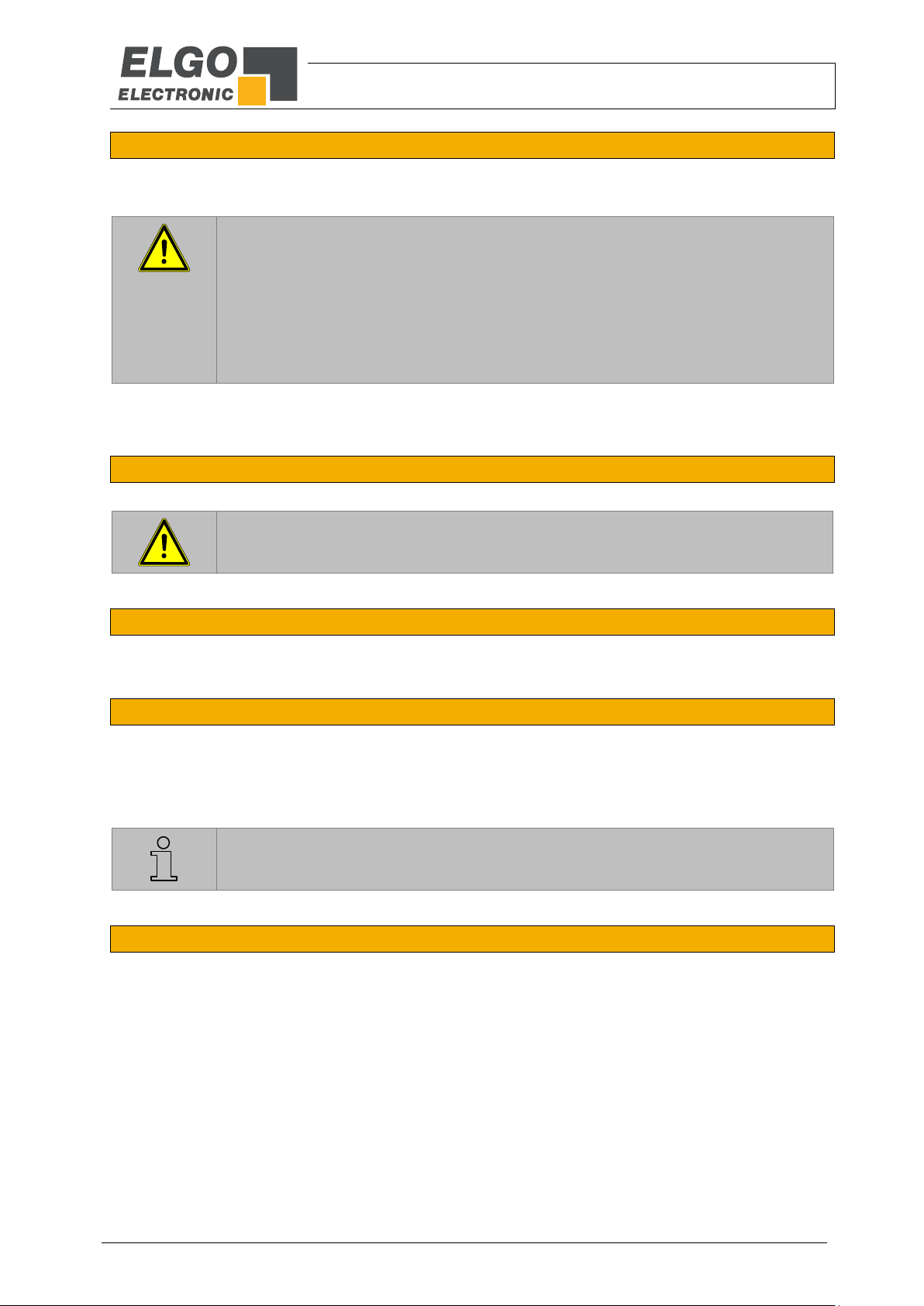
4.3 Dimensions of Magnetic Ring
4.3.1 Dimensions of Magnetic Ring without Protection Ring
Figure 3: Magnetic ring dimensions (without protection ring)
Usage up to maximum 1000 rpm
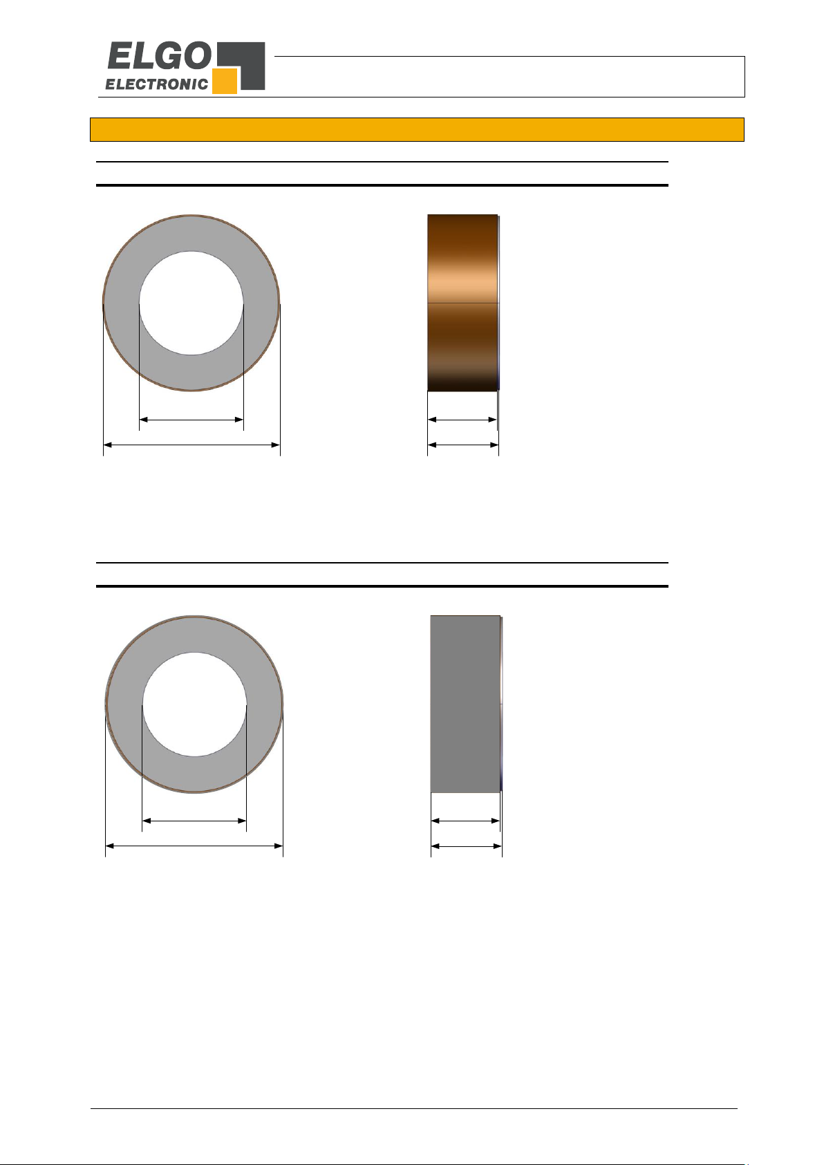
4.3.2 Dimensions of Magnetic Ring with Protection Ring
Figure 4: Magnetic ring dimensions (with protection ring)
Usage up to maximum 20000 rpm
Ø 50.95
Ø 30H7
20.60
20.00
Required shaft / tolerance: Ø 30h6
Ø 51.50
Ø 30H7
20.60
20.00
Required shaft / tolerance: Ø 30h6

Technical Data
- 10 -
4.4 Technical Data Sensor
EMAX-RO (standard version)
Mechanical Data
Measuring principle
Absolute
Repeat accuracy
+/- 1 Increment
System accuracy in µm at 20 °C
+/- (150 + 20 x L) / + / - 0.35° (type designation 010)
+/- (50 + 20 x L) / + / - 0.16° (type designation F10)
L = length in meter
Sensor distance to magnetic ring
max.1.0 mm without protection ring, max.0.45 mm with protection ring
Basic pole pitch
5mm
Sensor housing material
Aluminium
Sensor housing dimensions
L x B x H = 64.5 x 40.5 x 20 mm
Required magnetic ring
MR 00 051 030 206 0032 050 2 14021 (without protection ring)
MR 00 052 030 206 0032 050 2 14021 (with protection ring)
Max. measuring range
360°
Connection
Circular male plug 12-pin M12 outboard
Weight
ca. 90 g
Cable (Accessory): ca. 60 g per meter
Sensor cable
5 m standard length accessory (other on request)
Electrical Data
Power supply
10 ... 30 VDC
Ripple
< 5 %
Current consumption
max. 150 mA
Interfaces
SSI or CANopen (DS406) / on request: CAN BASIC ELGO (CN0),
RS422, addressable RS422, RS232 / in preparation: BISS-C
Resolution
16000 steps per turn
Max. speed
20000 rpm (dependent on interface)
0 to 1000 rpm without protecting ring
1000 to 20000 rpm with protecting ring
Cable length
max. 30 m (dependent on interface)
Ambient Conditions
Storage temperature
-25... +85 °C
Operation temperature
-10... +70 °C (-25... +85 °C) on request
Humidity
max. 95 %, not condensing
Protection class
IP50 (standard), IP65 (option V); higher protection class on request
4.5 Technical Data Magnetic Ring
Mechanical Data
Outer Ø
50.95 mm without protection ring
51.50 mm with protection ring
Inside Ø
30H7 (required shaft: 30h6)
Width
20.6 mm
Number of Poles / P
32
Basic pool pitch
5 mm
Material
Martensitic stainless steel (magnetic, hardenable), material
1.4021(X20Cr13)
Weight
ca. 190 g
Installation and First Start-Up
- 11 -
5Installation and First Start-Up
CAUTION
Please read the operating manual carefully before using the device! Strictly observe the In-
stallation instructions!
In case of damage caused by failure to observe this operating manual, the warranty expires.
ELGO is not liable for any secondary damage and for damage to persons, property or as-
sets.
The operator is obliged to take and to realize appropriate safety measures.
The first start-up may only be performed by staff that has been trained and authorized by the
operator.
5.1 Operating Area
WARNING!
Do not use the device in explosive or corrosive environments!
The device must not be installed close to sources of strong inductive or capacitive interfer-
ence or strong electrostatic fields!
CAUTION!
The electrical connections must be made by suitably qualified personnel in accordance with
local regulations.
The device may be designed for switchboard mounting. During work on the switchboard, all
components must be de-energized if there is a danger of touching the energized parts!
(protection against contacts)
Wiring works may only be performed in the de-energized state!
Thin cable strands have to be equipped with end sleeves!
Before switching on the device, connections and plug connectors have to be checked!
The device must be mounted in a way that it is protected against harmful environmental
influences such as splashing water, solvents, vibration, shock and severe pollution and the
operating temperature must not be exceeded.
WARNING!
Influence of external magnets
External magnetic fields must not exceed 64 mT (640 Oe; 52 kA/m) on the surface of the
magnetic ring as this could damage or destroy the code on the tape.

Installation and First Start-Up
- 12 -
5.2 Installing of the Sensor Head
5.2.1 Installing Tolerances
Note!
Distance between magnetic ring and active sensor area of the measuring system is between
0.50 mm and 1.00 mm without protection ring, and max. 0.45 mm with protection ring.
Observe the given tolerances when installing the system! Outside this area, proper function-
ing of the device cannot be guaranteed!
Install sensor with M3 screws, see Chapter “Dimensions of Sensor and Magnetic ring”
Table 1 Installing Tolerances
Tolerances
Ride height Sensor/Magnetic Ring
0.5 mm ... max. 1.0 mm without protection ring,
resp. max. 0.45 mm with protection ring
Roll/Pitch
The max. distance of 1 mm must not be exceeded
With protection ring the max. distance of 0.45 mm must not be exceeded
Lateral offset
+/- 1 mm
Figure 5: Installation tolerances of the sensor
5.2.2 Mounting direction of EMAX-RO Sensor to Magnetic Ring
Sensor and magnetic ring have to be mounted to the same direction (direction of arrow). The direction arrows
indicate the positive direction.
Abstand Sensor / Magnetring
Versatz
Kippwinkel
Rollwinkel
Pitch
Ride height /
Magnetic Ring
Lateral offset
Roll

Installation and First Start-Up
- 13 -
Figure 6: Mounting direction of EMAX-RO Sensor to Magnetic Ring
5.2.3 Offset
After the installation of the magnetic tape and the measuring system (EMAX-RO) a value is transmitted by the
interface. Because this value does not conform to the machine zero point, an offset should to be deposited at
the controller side.
NOTE!
The offset should be arranged at any change from measurement system (sensor head) or
magnetic ring.
5.2.4 Activation of the device
The device starts automatically after operation voltage application. Depending on the interface may be addi-
tional steps required to activate the EMAX-RO.
EMAX-RO Sensor
Distance detection via
LED
Symbolic illustration
Fine interpolation track
Direction arrow
for assembly Absolute track

Installation and First Start-Up
- 14 -
5.3 Magnetic Ring mounting suggestions
The magnetic ring may be mounted in various ways on a shaft. The examples will below show non-binding pro-
posals how the magnetic ring can be installed.
5.3.1 Example for adhesive mounting:
Figure 7: Magnetic ring: example for adhesive mounting
5.3.2 Example for screw mounting
Figure 8: Magnetic ring: example for screw mounting
Ø 30h6
Steel shaft with h6 fit
EMAX RO magnetic ring
Loctite 648 adhesive
Ø 30h6
Shaft shoulder with h6 fit and
female thread on the face
Steel shaft
EMAX RO magnetic ring A little space
for tensioning
Cover and tension disc
with centred drill hole
Fixing and tensioning screw

Interfaces and Assignment
- 15 -
6Interfaces and Assignment
6.1 Pin Assignment
Table 2 Pin Assignment SSI / optionally with incremental signals
The colours are valid with the DKA signal cable which is available as accessories.
Cable Plug 12 pol M12x1
PIN-Nr.
Function
34
5
6
78 9
11
12 10
2
1
1 (white)
0 V/GND
2 (brown)
10 …30 VDC
3 (green)
CLK+
4 (yellow)
CLK–
5 (grey)
DATA+
6 (pink)
DATA–
7 (blue)
COS+ or B+
8 (red)
COS–or B–
9 (black)
SIN+ or A+
10 (violet)
SIN–or A–
11 NC
NC
12 NC
NC
Table 3 Pin Assignment CA0 / optionally with incremental signals
The colours are valid with the DKA signal cable which is available as accessories.
Cable Plug 12 pol M12x1
PIN-Nr.
Function
34
5
6
78 9
11
12 10
2
1
1 (white)
0 V/GND
2 (brown)
10 …30 VDC
3 (green)
CAN-LOW
4 (yellow)
CAN-HIGH
5 (grey)
NC
6 (pink)
NC
7 (blue)
COS+ or B+
8 (red)
COS–or B–
9 (black)
SIN+ or A+
10 (violet)
SIN–or A–
11 NC
NC
12 NC
NC

Interfaces and Assignment
- 16 -
6.2 Interfaces
The following chapters give detailed information about the connections and interfaces.
6.2.1 Interface SSI (option SB0 and SG0)
If the clock is not interrupted for the time Tm-T/2 (output of further 25 periods), the shift register clocks once
again the same data value (error recognition in evaluation).
Some encoders contain a Power Failure Bit (PFB):
With EMAX-RO the PFB is always „LOW“.
Figure 9SSI Interface
6.2.2 Interface CANopen (option CA0)
As standard the EMAX-RO measuring system is equipped with a CANopen standard interface DS406, when
ordering option CA0.
The following identifiers are given:
CAN - Identifier
(4 Byte telegram)
180 (16) = Identifier
First 4 bytes = Position
Baud rate = 250 KB / s
Figure 10: CAN Interface
ABS-Position
xxh
LSB
xxh
xxh
MSB
xxh
Not inverted SSI Clock
Interfaces and Assignment
- 17 -
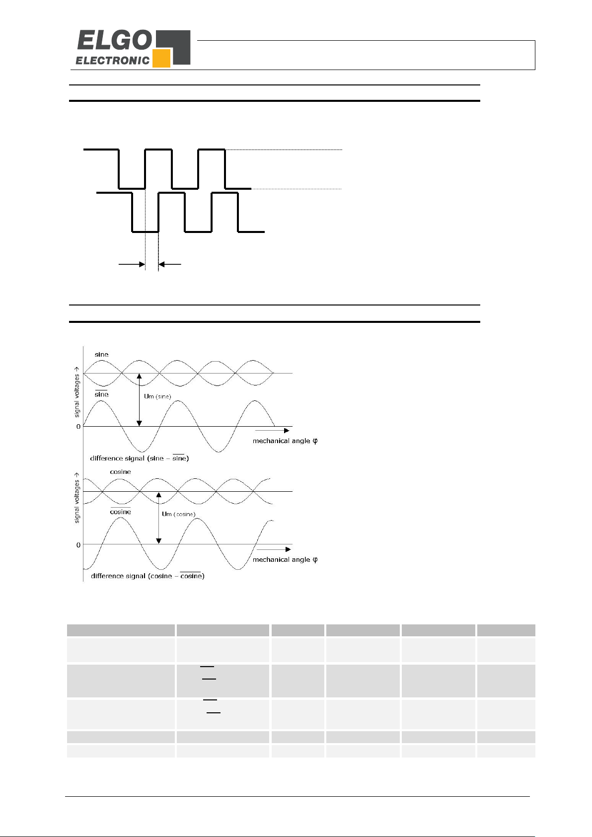
6.2.3 Incremental Signal TTL / HTL
As an option, there are two 90 ° phase shifted rectangle signals (compatible to rotary encoders) with HTL or TTL
output level (push-pull, push / pull).
Figure 11: A / B - Incremental Signal TTL / HTL
6.2.4 Sine-Cosine Incremental Signal (Option SC50)
Sine-Cosine signals with 1 Vss are available as an option (push-pull output stage, short-circuit proof)
Parameter
Description
min.
typ.
max.
unit
Medium voltage
at (sin),
at (cos)
2.4
2.5
2.6
V
Amplitude
sin –sin
cos - cos
400
500
600
mV
proportion
(sin –sin) /
(cos –cos)
0.9
1.0
1.1
-
Phase shift
φ
89
90
91
° degrees
Distortion factor
K
-
-
2
%
90°
HTL (10 …30 V)
TTL (5 V)
0 VDC
Figure 12: Sine-Cosine signals
Disturbances, Maintenance, Cleaning
- 18 -
7Disturbances, Maintenance, Cleaning
This chapter describes possible causes for disturbances and measures for their removal. In case of increased disturbances, please follow the
measures for fault clearance in chapter 7.1.
In case of disturbances that cannot be eliminated by following the advice and the fault clearance measures given here, please contact the
manufacturer (see second page).
7.1 Fault Clearance
CAUTION!
The device, the connection line and the signal cable must not be installed next to sources of interference that emit
strong inductive or capacitive interference or strong electrostatic fields.
External perturbations can be avoided thorough suitable cable routing.
The screen of the signal output cable should only be connected to the following circuit on one side. The screens
should not be grounded on both sides. Signal cables always have to be routed separately from the load power line.
A safety distance of at least 0,5 m has to be kept from inductive and capacitive sources of interference such as con-
tactors, relays, motors, switching power supplies, clocked controllers etc!
If interferences occur in spite of all the items stated above being observed, please proceed as follows:
1. Installation of RC-circuits via contactor coils of AC-contactors (e.g. 0,1 µF / 100 Ω)
2. Installation of recovery diodes via DC-inductors
3. Installation of RC-circuits via the different motor phases (in the terminal box of the motor)
4. Do not connect protective earth and ground
5. Connect a mains filter ahead of the external power pack
7.2 Re-start after Fault Clearance
After the fault clearance:
1. Reset the emergency stop mechanism if necessary
2. Reset the error report at the super-ordinate system if necessary.
3. Ensure that there are no persons in the danger area.
4. Follow the instructions from chapter 5.
WARNING!
Danger of injury through non-conventional fault clearance!
Non-conventional fault clearance can lead to severe injuries and damage of property.
Therefore:
Any work to clear the faults may only be performed by sufficiently qualified staff
Arrange enough space before starting the works
Make sure that the mounting area is clean and tidy. Loose components and tools are sources of accidents.
If components need to be replaced:
Pay attention to a correct installation of the spare parts.
Reinstall all the fixing elements properly
Before turning on the device, ensure that all covers and safety equipment is installed correctly and functions
properly

Disturbances, Maintenance, Cleaning
- 19 -
7.3 Maintenance
The device is maintenance-free.
WARNING!
Danger through non-conventional maintenance!
Non-conventional maintenance can lead to severe injuries and damage of property.
Therefore:
Maintenance works may only be completed by staff that has been authorized and trained by the operator.
7.4 Cleaning
WARNING!
The device can only be cleaned with a damp cloth, do not use aggressive cleanser!
Type Designation
- 20 -
8Type Designation
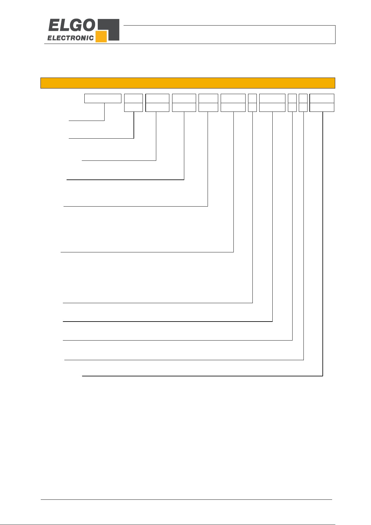
8.1 Type Designation EMAX-RO
Figure 13: Type designation EMAX-RO
RMAX XX XXX XXX XXX XXXX X XXXX X X XXXX
AA BBB CCC DDD EEEE F GGGG H I JJJJ
Series/Type:
RMAX = EMAX RO measuring system
SN-number:
00 = standrad
Signal cable length:
000 = without cable (standard)
Resolution:
010 =10 µm
Interface:
SB0 = SSI Interface (25 Bit Binary code)
SG0 = SSI Interface (25 Bit Gray code)
CA0 = CANopen (DS 406)
CN0 = CAN BASIC ELGO (on request)
420 = RS422 (on request)
A20 = addressable RS422 (on request)
230 = RS232 (on request)
Bit rate:
09k6 = 9600 Bit/s-standard bit rate with RS422 (420)
19k2 = 19200 Bit/s with RS422
38k4 = 38400 Bit/s with RS422
125k = 125000 Bit/s with CAN
250k = 250000 Bit/s with CAN
500k = 500000 Bit/s with CAN
1MHz = 1000000 Bit/s with CAN
Options:
F = device address 0...F standard configuration address: 0)
Options:
---- = standard version (always with 12-pole M12 connector)
Options:
V = sealed version
Incremental signals:
H2N5 = incremental square-wave signals HTL with 2,5 µm resolution
H005 = incremental square-wave signals HTL with 5 µm resolution
H010 = incremental square-wave signals HTL with 10 µm resolution
H025 = incremental square-wave signals HTL with 25 µm resolution
T2N5 = incremental square-wave signals TTL with 2,5 µm resolution
T005 = incremental square-wave signals TTL with 5 µm resolution
T010 = incremental square-wave signals TTL with 10 µm resolution
SC50 = sine-cosine signals 1 Vss, 5 mm pole-pitch
*Refers to the absolute position and not on the optional incremental position
Options :
A = without terminating resistor
Table of contents
Other ELGO Electronic Media Converter manuals

ELGO Electronic
ELGO Electronic LIMAX02 Series User manual

ELGO Electronic
ELGO Electronic EMSC2 Series User manual

ELGO Electronic
ELGO Electronic PMIX Series User manual

ELGO Electronic
ELGO Electronic GMIX1A Series User manual

ELGO Electronic
ELGO Electronic GMIX2 Series User manual

ELGO Electronic
ELGO Electronic FMax Series User manual


