Elgo LIMAX Safe SG User manual
Operating Manual
LIMAX Safe SG/SC
Magnetic Absolute Shaft Information System with Safety Functions
D-100988 / Rev. 9 / 2020-04-09
799000965


- 3 -
Contents
1General.............................................................................................. 8
1.1 Information Operating Manual .............................................................................8
1.2 References.........................................................................................................8
1.3 Terms and Abbreviations......................................................................................8
1.4 Explanation of Symbols......................................................................................10
1.5 Statement of Warranties.....................................................................................11
1.6Demounting and Disposal..................................................................................11
2Safety ............................................................................................... 12
2.1 General Causes of Risk......................................................................................12
2.2 Personal Protective Equipment.............................................................................12
2.3 Conventional Use .............................................................................................13
3Transport and Storage .................................................................... 14
3.1 Safety Instructions for Transport, Unpacking and Loading ........................................14
3.2 Handling of Packaging Material ..........................................................................14
3.3 Inspection of Transport ......................................................................................14
3.4 Storage ...........................................................................................................14
4Product Features .............................................................................. 15
5Technical Data ................................................................................. 16
5.1 Identification ....................................................................................................16
5.2 Dimensions Safe Box .........................................................................................17
5.3 Technical Data Safe Box ....................................................................................18
6Constraints for Use .......................................................................... 20
6.1 General constraints for LIMAX Safe SG/SC, 110 V / 230 V......................................20
6.2 Additional constraints for LIMAX Safe SC...............................................................20
6.3 Additional constraints for LIMAX Safe SG ..............................................................21
6.4 Special constraints for 110 V Version ...................................................................21
6.5 Special constraints for 230 V Version ...................................................................21
6.6 Prevention against external door contact bridging ..................................................21
7Type Designation ............................................................................. 23
7.1 Available Versions.............................................................................................23
8Installation....................................................................................... 24
8.1 Operating Area ................................................................................................24
8.2 Mechanical Installation ......................................................................................25
8.3 Electrical Installation..........................................................................................25
9Commissioning................................................................................. 38
9.1 Check of door monitoring ..................................................................................38

Contents
- 4 -
9.2 Operation modes of the Safe Box........................................................................39
9.3 Learning of the floor image ................................................................................40
10 Design and Functions ...................................................................... 45
10.1 Basic Design ....................................................................................................45
10.2 Guidelines for the Implementation in the Control ...................................................46
10.3 Safety Functions................................................................................................48
10.4 Operating Modes .............................................................................................53
10.5 Signaling of the Safe Box....................................................................................54
10.6Connectors and Interfaces..................................................................................55
11 During operation ............................................................................. 58
11.1 Relay Test ........................................................................................................58
11.2 Readjusting the floor levels .................................................................................59
11.3 Triggering the safety functions.............................................................................59
11.4 Settable Parameters...........................................................................................62
11.5 Error Status due to System Error...........................................................................63
11.6 Error Codes .....................................................................................................63
11.7 Reset to Delivery State........................................................................................66
11.8 The Fault Register .............................................................................................66
11.9 Direct Relay Access (Option)...............................................................................68
11.10 Contact Test (Option) ........................................................................................68
12 Safety Function Check ...................................................................... 71
12.1 Software Identification .......................................................................................71
12.2 Correct Wiring due to Type SG/SC......................................................................71
12.3 Door Monitoring and Capacitive Coupling ...........................................................71
12.4 Examination of Door Switches and Locking Switches ...............................................71
12.5 Set Nominal Speed ...........................................................................................71
12.6 Flush Positions of the Floors................................................................................72
12.7 Positions..........................................................................................................72
12.8 Inspection Speed ..............................................................................................72
12.9 Final Limit Switches ...........................................................................................73
12.10 Inspection........................................................................................................73
12.11 Inspection Limit Switches ....................................................................................73
12.12 Setting Error Level 4 ..........................................................................................74
12.13 Deceleration Control towards the Shaft End...........................................................74
12.14 Unintended Car Movement ................................................................................74
12.15 Malfunction of the SGC Feedback.......................................................................75
12.16 Door Zone Indicator..........................................................................................75
12.17 Test of Motor Brake...........................................................................................75
12.18 Tripping of Safety Gear......................................................................................75
12.19 Initial and annual examination of LIMAX33 RED/LIMAX44 RED ................................75
12.20 Not tested Safety Functions.................................................................................76

Contents
- 5 -
13 Disturbances .................................................................................... 77
13.1 Fault Clearance................................................................................................77
13.2 Re-Start after Fault Clearance .............................................................................78
14 Repairs / Maintenance .................................................................... 78
15 Replacing Components .................................................................... 79
15.1 Replacing LIMAX33 RED/LIMAX44 RED ................................................................79
15.2 Replacing Magnetic Tape...................................................................................79
15.3 Replacing the Safe Box ......................................................................................79
16 Cleaning........................................................................................... 80
AOver-speed Curve Calculation......................................................... 81
A.1 Final tripping speed...........................................................................................81
A.2 Pre-tripping speed.............................................................................................82

Contents
- 6 -
List of Figures
Figure 1: Type label for identification of the Safe Box ................................................................................. 16
Figure 2: Info label with additional information ......................................................................................... 16
Figure 3: Safe Box dimensions ................................................................................................................. 17
Figure 4: Neutral conductor connection to avoid door contact bridging by indicator circuit ........................... 22
Figure 5: PCB Layout to avoid door contact bridging by indicator circuit...................................................... 22
Figure 6: Type designation ...................................................................................................................... 23
Figure 7: Installation circuit diagram for LIMAX Safe SC with (semi-)guided Sensor ....................................... 27
Figure 8: Installation circuit diagram for LIMAX Safe SC with unguided Sensor ............................................. 28
Figure 9: Circuit diagram of LIMAX Safe SG with (semi)guided sensor, SGC connected to an
electromechanically driven blocking device on the speed governor ................................................. 29
Figure 10: Circuit diagram of LIMAX Safe SG with unguided sensor, SGC connected to an electromechanically
driven blocking device on the speed governor............................................................................... 30
Figure 11: Circuit diagram of LIMAX Safe SG, SGC connected to an electromechanically driven safety gear
(guided Sensor) .......................................................................................................................... 31
Figure 12: Circuit diagram of LIMAX Safe SG, SGC connected to an electromechanically driven safety gear
(unguided Sensor) ...................................................................................................................... 32
Figure 13: Example of an installation which should be avoided (top) and an advantageous installation (bottom).
................................................................................................................................................. 34
Figure 14: Connection diagram for power, CAN communication and reset input ......................................... 35
Figure 15: SGC integration diagram for LIMAX Safe SG ............................................................................ 36
Figure 16: SGC integration diagram for LIMAX Safe SC............................................................................. 36
Figure 17: Connection of door zone indicator ........................................................................................... 37
Figure 18: Operation modes ................................................................................................................... 39
Figure 19: Components of the Safe Box.................................................................................................... 46
Figure 20: Behavior of the upper limit switches.......................................................................................... 51
Figure 21: LED signals visible through the window ..................................................................................... 54
Figure 22: Electrical sensor connection..................................................................................................... 57
Figure 23: Dependency final tripping speed as a function of rated speed..................................................... 81
Figure 24: Dependencies of pre-tripping and final tripping speed as functions of rated speed ....................... 82
List of Tables
Table 1: Pin assignment PIO cable........................................................................................................... 26
Table 2: Pin assignment SCA cable .......................................................................................................... 26
Table 3: Wire assignment of OC.............................................................................................................. 33
Table 4: Wire assignment of NOC and DCS............................................................................................. 33
Table 5: Wire assignment inspection control ............................................................................................. 34
Table 6: Wire assignment power supply and battery supply......................................................................... 35
Table 7: Wire assignment reset input ........................................................................................................ 35
Table 8: Wire assignment of SGC output und SGC-FB input ...................................................................... 35
Table 9: Wire assignment door zone indication ......................................................................................... 37
Table 10: Wire assignment CAN.............................................................................................................. 37
Table 11: Overview safety functions ......................................................................................................... 48
Table 12: Limit switch behavior ................................................................................................................ 50
Table 13: Safety output states in pre-commissioning mode......................................................................... 53
Table 14: Meaning of LED signals............................................................................................................ 54
Table 15: Wire assignment power supply and battery supply....................................................................... 55
Table 16: Wire assignment CAN.............................................................................................................. 55
Table 17: Wire assignment of safety relevant actuators .............................................................................. 56
Table 18: Wire assignment door contact input .......................................................................................... 56
Table 19: Wire assignment inspection control ........................................................................................... 56
Table 20: Wire assignment door zone indication ....................................................................................... 57
Table 21: Wire assignment reset input ...................................................................................................... 57
Table 22: Pin assignment sensor connector............................................................................................... 57
Table 23: Triggering of the safety functions ............................................................................................... 60

Contents
- 7 -
Table 24: Settable parameter values ........................................................................................................ 62
Table 25: Error codes ............................................................................................................................. 63
General
- 8 -
1General
1.1 Information Operating Manual
This manual contains important information regarding the handling of the device.
For your own safety and operational safety, please observe all safety warnings and instructions.
Precondition for safe operation is the compliance with the specified safety and handling instructions.
Moreover, the existing local accident prevention regulations and the general safety rules at the site of operation
have to be observed.
Please read the operating manual carefully before starting to work with the device!
It is part of the product and should be kept close to the device and accessible for the staff at any time. The illus-
trations in the manual are for better demonstration of the facts. They are not necessarily to scale and can slightly
differ from the actual design.
1.2 References
/CO_SPECS/ LIMAX Safe SG/SC CANopen Specifications https://support.elgo.li/man/D-100968
/SENS_MANUAL/ Operating Manual LIMAX33 RED https://support.elgo.li/man/D-100218
Operating Manual LIMAX44 RED https://support.elgo.li/man/D-103836
/CiA DR303-3/ CiA Draft Recommendation 303, Part 3: Indicator specification; CAN in Automation
1.3 Terms and Abbreviations
Abbreviation / Term
Explanation
LSB
Least Significant Bit
MSB
Most Significant Bit
Floor
Synonym: landing
Shaft image
Number of floors and positions of the floors of the lift where LIMAX Safe SG/SC is installed
Synonym: floor image
Inspection control
Synonym: inspection control, inspection pod
Remark: the EN81 talks about “inspection control station”
Recall panel
Synonym: recall control, emergency control, recall pod
Remark: one will not find this term in the EN81.
There one can find: “means of emergency electrical operation”, “emergency electrical oper-
ation switch”, “emergency electrical operation button” for the devices an “emergency electri-
cal operation” for the process. These terms are not used here because they are very long
Control
Synonym: lift control, elevator control
LIMAX Safe SG/SC
Complete system (Safe Box, LIMAX33 RED/LIMAX44 RED and magnetic tape).
A device may be a LIMAX Safe SG or a LIMAX Safe SC. The type of the device (SG or SC)
cannot be changed. The type SG/SC is noted on the identification label. Some con-
straints/hints/instructions for use are each only applicable for LIMAX Safe SG respectively
LIMAX Safe SC.
These special paragraphs in this manual are clearly marked. The instructions for the present
device must be followed. The instructions for the other type cannot be followed.
LIMAX Safe SG
Concrete type of the LIMAX SG/SC: SGC must be connected to an external electromechani-
cal actor. This actuator may operate a suitable safety gear directly or it may operate a con-
ventional safety gear indirectly by blocking the speed governor.
LIMAX Safe SC
Concrete type of the LIMAX SG/SC: SGC must be wired in the safety circuit. No operation of
safety gear- neither directly not indirectly –is provided by LIMAX Safe SC.
LIMAX33 RED
Component of the overall system LIMAX Safe, safe position sensor up to 262 m
LIMAX44 RED
Component of the overall system LIMAX Safe, safe position sensor up to 786 m
General
- 9 -
Abbreviation / Term
Explanation
Magnetic tape
Magnetized tape with absolute coding, part of the position sensor system
Safe Box
Component of the overall system LIMAX Safe SG/SC, carries out the specified safety func-
tions and additional functions based on position information coming from LIMAX33
RED/LIMAX44 RED and on the state of additional inputs.
The Type SG or SC is determined by the Safe Box (Safe Box SG or Safe Box SC). The LI-
MAX33 RED/LIMAX44 RED is identical for LIMAX Safe SG and LIMAX Safe SC as well.
Sight glass
Window on top of Safe Box. LEDs can be seen through the sight glass. It is prohibited to
remove the sight glass.
Synonym: window
PIO cable
Power and I/O cable; contains wires for power supply, digital I/O and communication inter-
face to the control.
SCA cable
Safety circuit and actuators cable; contains wires for interfacing the door contact input (DCS)
and the safety actuators/relays.
Pre-commissioning mode
Operation mode of Safe Box. The shaft image is empty in pre-commissioning mode.
Teach mode
Operation mode of Safe Box. The shaft image is learned in teach mode
Adjustment mode
Operation mode of Safe Box. The floor positions can be adjusted in adjustment mode.
Normal mode
Normal operation mode
Temporary reference posi-
tions
Reference positions used to determine positions of final limit switches and inspection limit
switches in teach mode. Calculation of the positions of the final limit switches and inspection
limit switches in teach mode is based on the temporary reference position because the lowest
and highest floors are not known yet (in normal and adjustment mode, the lowest and high-
est floor are the basis for the calculation of the positions of the final limit switches and in-
spection limit switches).
The temporary reference positions can be learned in teach mode.
Technician
Suitably trained person entrusted with installation and commissioning of LIMAX Safe SG/SC
or suitably trained person entrusted with troubleshooting
Auditor
Person of a notified body responsible for initial inspection of a lift where LIMAX Safe SG/SC
is installed or responsible for the annual inspection
SC
Safety circuit
Rated speed
The rated (nominal) speed of the Safe Box and the elevator where the Safe Box is installed in
must fit. The rated speed is noted on the identification label. It cannot be changed.
Synonym: nominal speed
NOC
Non bridgeable relay contact
Relay contact to be wired in the safety circuit due to the instructions given in this manual.
OC
Bridgeable relay contact
Relay contact to be wired in the safety circuit doe to the instructions given in this manual
SGC
Relay contact to be wired:
To an external electromechanical actuator in case of LIMAX Safe SG
In the safety circuit in case of LIMAX Safe SC
SGC-FB
feedback contact from the switch served by the safety gear or the blocking device on the
speed governor, only used for LIMAX Safe SG
DCS
Door contact state
UPS
Uninterruptible power supply
General
- 10 -
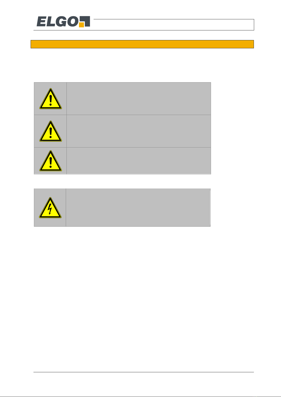
1.4 Explanation of Symbols
Special notes in this manual are characterized by symbols.
The notes are introduced by signal words which express the magnitude of danger.
Please follow this advice and act carefully in order to avoid accidents and damage and injuries.
Warning notes:
DANGER!
This symbol in connection with the signal word “Danger” indicates an
immediate danger for the life and health of persons.
Failure to heed these instructions can result in serious damage to
health and even fatal injury.
WARNING!
This symbol in connection with the word „Warning” means a possibly
impending danger for the life and health of persons.
Failure to heed these instructions can result in serious damage to
health and even fatal injury.
CAUTION!
This symbol in connection with the signal word “Caution” indicates a
possibly dangerous situation. Failure to heed these instructions can
lead to minor injuries or damage of property.
Special safety instructions:
DANGER!
This symbol in connection with the signal word “Danger” indicates an
immediate danger for the life and health of persons due to voltage.
Failure to heed these instructions can result in serious damage to
health and even fatal injury. The operations may only be carried out by
a professional electrician.
References:
(1.2) Marks a reference to chapter 1.2 of this manual.
(DOC 3.4) Marks a reference to chapter 3.4 of the document DOC
General
- 11 -
Tips and recommendations:
NOTE!
…points out useful tips and recommendations as well as information
for an efficient and trouble-free operation.
Implementation guidelines:
This comment appears wherever there are certain requirements on the lift control which have
to be implemented in the CANopen protocol so that LIMAX Safe SG/SC can function proper-
ly. Further details can be found in the CANopen specs.
At certain points it is necessary that the technician can read out certain internal values, which
are received by the control via CANopen from LIMAX Safe SG/SC. If this is clear from the
context, the control programmer must implement the ability to output these values in the lift
control. Details such as the menu navigation of the control are not covered in this document,
but can be found in the documentation of the controls manufacturer.
It is strictly prohibited to implement things marked by this symbol in the lift control.
1.5 Statement of Warranties
The statement of warranties is enclosed separately in the sales documents.
Guarantee:
The producer guarantees the functional capability of the process engineering and the selected parameters. The
period of warranty is one year and begins with the date of delivery.
1.6 Demounting and Disposal
Unless acceptance and disposal of returned goods are agreed upon, demount the device considering the safety
instructions of this manual and dispose it with respect to the environment.
Before demounting:
Disconnect the power supply and secure against re-start. Then disconnect the supply lines physically and dis-
charge remaining energy. Remove operational supplies and other material.
Disposal:
Recycle the decomposed elements:
Metal components in scrap metal
Electronic components in electronic scrap
Recycle plastic components
Dispose the remaining components according to their material consistence
CAUTION!
Wrong disposal causes environmental damages!
Electronic scrap, electronic components, lubricants and other auxiliary
materials are subject to special refuse and can only be disposed by
authorized specialists!
Local authorities and waste management facilities provide information about environmentally sound disposal.
Safety
- 12 -
2Safety
CAUTION!
Please read the operating manual carefully, before using the device!
Observe the installation instructions!
Only start up the device if you have understood the operating manual.
The operating company is obliged to take appropriate safety measure.
The initial operation may only be performed by qualified and trained
staff.
Selection and installation of the devices as well as their embedding into
the controlling system require qualified knowledge of the applicable
laws and normative requirements on the part of the machine manufac-
turer.
2.1 General Causes of Risk
This chapter gives an overview of all important safety aspects to guarantee an optimal protection of employees
and a safe and trouble-free operation. Non-observance of the instructions mentioned in this operating manual
can result in hazardous situations.
2.2 Personal Protective Equipment
Employees have to wear protective clothing during the installation of the device to minimize danger of health.
Therefore:
Change into protective clothing before performing the works and wear them throughout the process.
Additionally observe the labels regarding protective clothing in the operating area.
Protective clothing:
PROTECTIVE CLOTHING
… is close-fitting working clothing with light tear strength, tight sleeves
and without distant parts. It serves preliminarily for protection against
being gripped by flexible machine parts.
Do not wear rings, necklaces or other jewellery.
PROTECTIVE GLOVES
…for protecting the hands against abrasion, wear and other injury of
the skin.
PROTECTIVE HELMET
…for protection against injuries of the head.
Safety
- 13 -
2.3 Conventional Use
The product described in this manual was developed to execute safety-related functions as a part of an entire
assembly or machine. It is the responsibility of the manufacturer of a machine or installation to ensure the prop-
er operation of the system. The ELGO-device is conceived only for the intended use described in this manual.
The LIMAX Safe SG/SC - ELGO- length measuring system serves only to meas-
ure lengths and to fulfil the safety functions in (see 10.3)
CAUTION!
Danger through non-conventional use!
Non-intended use and non-observance of this operating manual can
lead to dangerous situations.
Therefore:
Only use the device as described
Strictly follow the instructions of this manual
Avoid in particular:
Remodelling, refitting or changing of the construction or single
components with the intention to alter the functionality or
scope of the device.
Claims resulting from damages due to non-conventional use are not possible.
Only the operator is liable for damages caused by non-conventional use.
Transport and Storage
- 14 -
3Transport and Storage
3.1 Safety Instructions for Transport, Unpacking and Loading
CAUTION!
Transport the package (box, palette etc.) professionally.
Do not throw, hit or fold it.
3.2 Handling of Packaging Material
Notes for proper disposal: 1.6
3.3 Inspection of Transport
Check the delivery immediately after the receipt for completeness and transport damage.
In case of externally recognizable transport damages:
Do not accept the delivery or only accept under reserve.
Note the extent of damages on the transportation documents or delivery note.
File complaint immediately.
NOTE!
Claim any damage immediately after recognizing it. The claims for
damage must be filed in the lawful reclaim periods.
3.4 Storage
Store the device only under the following conditions:
Do not store outside
Keep dry and dust-free
Do not expose to aggressive media
Protect from direct sun light
Avoid mechanical shocks
Storage temperature (5 Technical Data) needs to be observed
Relative humidity (5 Technical Data) must not be exceeded
Inspect packages regularly if stored for an extensive period of time (>3 months)

Product Features
- 15 -
4Product Features
LIMAX Safe SG/SC is a safety device fulfilling various safety function named in EN81.
In order to do this, LIMAX Safe SG/SC needs several pieces of information:
Position of lift cabin determined by the subsystem LIMAX33 RED/LIMAX44 RED - a safe position sensor -
Velocity of the lift cabin, is derived by LIMAX Safe SG/SC from the position values
Shaft image, learned by LIMAX Safe SG/SC during commissioning
Various inputs from safety circuit, inspection control, an external button and an external feedback
switch. The external elements are wired as described in chapter 8.3 to the corresponding inputs of
LIMAX Safe SG/SC
Nominal speed of the lift in which LIMAX Safe SG/SC is installed. The nominal speed is adjusted in the
factory and marked on the Safe Box. Changing the nominal speed is strictly prohibited.
LIMAX Safe SG/SC contains three potential-free contacts as safety relevant actuators: OC, NOC and SGC:
The bridgeable relay contact (OC) is intended to open the safety circuit on a spot, which can be
bridged by recall panel
The non-bridgeable relay contact (NOC) is intended to open the safety circuit which cannot be bridged
at all
The safety gear relay contact (SGC) is intended:
to open the supply circuit of the trip coil of the blocking device on the speed governor (in case the
option with electronic trigger of speed governor is chosen). This applies to LIMAX Safe SG. The trip
coil and the blocking device do not belong to the certificate of LIMAX Safe SG/SC.
to open the supply circuit of the trip coil of the electromechanically triggered safety gear (in case
the option with electromechanically triggered safety gear). This applies to LIMAX Safe SG. The trip
coil and the mechanical part of the safety gear do not belong to the certificate of LIMAX Safe
SG/SC.
to open the safety circuit which cannot be bridged at all. This applies to LIMAX Safe SC
They have to be integrated into the lift as described in chapter 8.3.
Additional LIMAX Safe SG/SC contains a potential free contact in order to signalize door zones as emergency
rescue aid.
LIMAX Safe SG/SC is connected with the lift control by CAN interface. LIMAX Safe SG/SC provides position and
velocity of the lift cabin to the control via the CAN interface.
Additional data is transferred via CAN interface used for:
Diagnostics
Comparing the shaft image stored in lift control and shaft image stored in LIMAX Safe SG/SC
Signals for door bridging
Learning temporary reference positions in order to keep the technician safe during teach mode
Signals to learn and readjust the shaft image
Request to carry out a relay test
Changing of values of safety-relevant parameters (only within allowed limits)
For details refer to /CO_SPECS/.
Dependent on the safety circuit voltage the suitable version of the Safe Box as a component of the LIMAX Safe
SG/SC system has to be installed.
There is one variant for each of the following safety circuit voltages:
110 VAC, 50 Hz (with Sensor: LIMAX33 RED)
230 VAC, 50 Hz (with Sensor: LIMAX33 RED or LIMAX44 RED)
Technical Data
- 16 -
5Technical Data
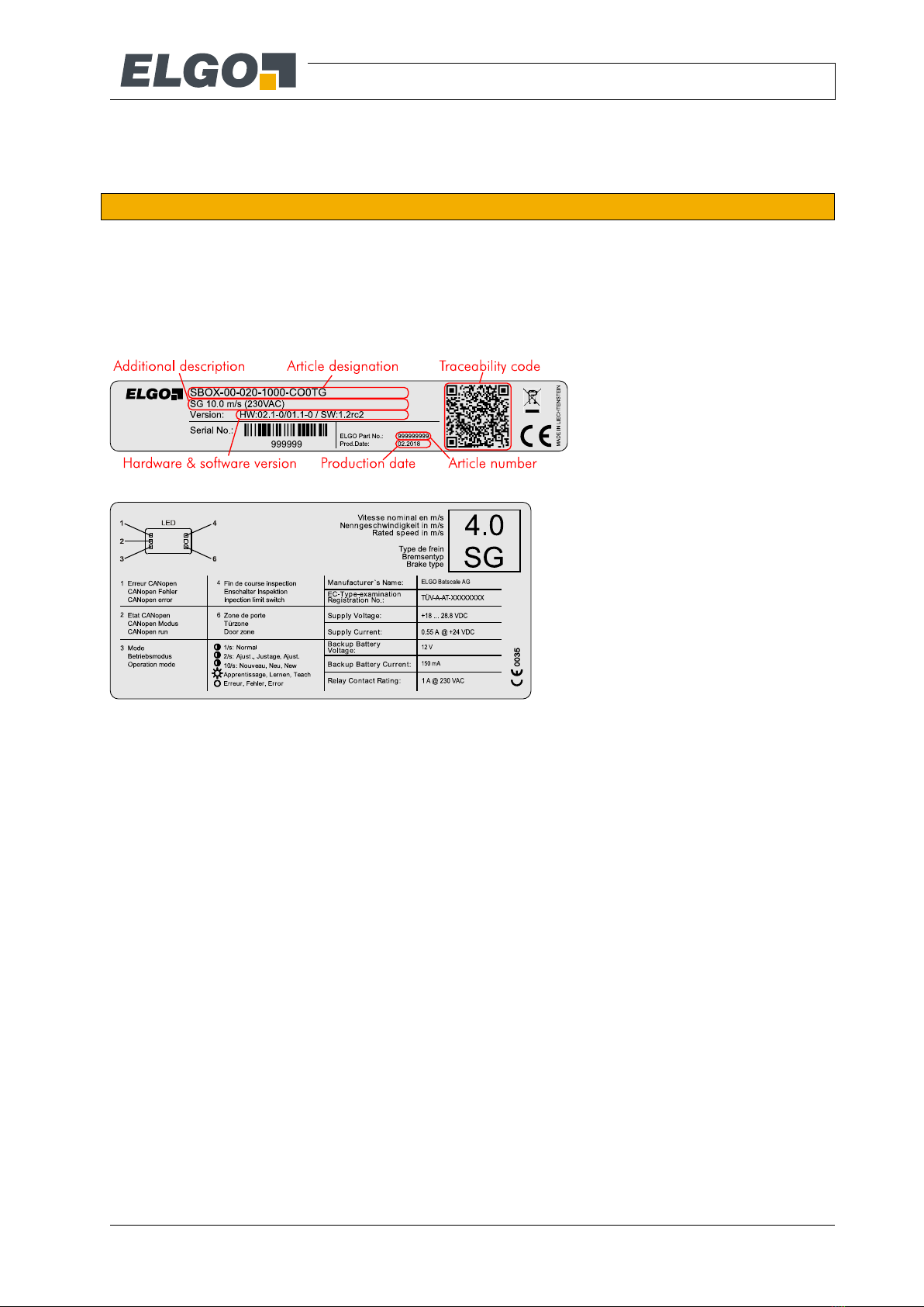
5.1 Identification
The type label serves for the identification of the unit. It is located on the housing of the sensor and gives the
exact type designation (Article designation = order reference, see type designation, chapter 7) with the corre-
sponding part number (ELGO Part No.).
Furthermore, the type label contains the hardware and software versions, a unique, traceable device number
(Serial No.), the production date (Batch No.) as well as (if available) the customer part number (Ident No./Type).
When corresponding with ELGO always indicate this data.
Figure 1: Type label for identification of the Safe Box
Figure 2: Info label with additional information
Concerning Figure 2, the rated speed (here: 4.0) and the “Brake type” (here: SG) are only examples.
Technical Data
- 17 -
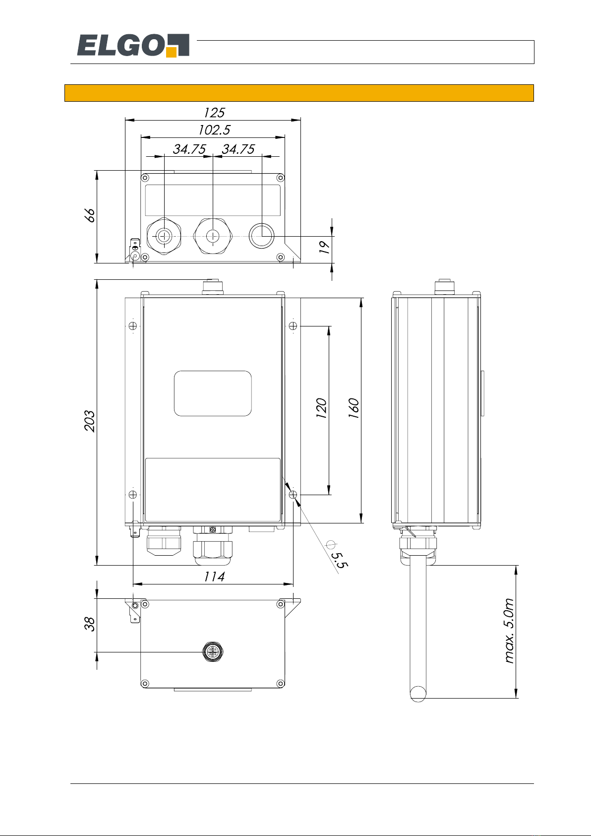
5.2 Dimensions Safe Box
Figure 3: Safe Box dimensions

Technical Data
- 18 -
5.3 Technical Data Safe Box
LIMAX Safe SG/SC (General technical data)
Mechanical Data
Maximum lifting height:
Sensor LIMAX33 RED:
125 m / 262 m (6.4 Special constraints for 110 V Version)
Sensor LIMAX44 RED:
786 m (only for 230 V Version)
Maximum number of floors:
127
Maximum nominal speed:
10 m/s
Measuring principle:
absolute
Resolution:
7 Type Designation
Repeat accuracy:
+/- 1 Increment
System accuracy in µm at 20°C:
+/- (1000 µm + 100 µm x L) L = measuring length in meters
Dimensions (without cable):
L x B x H = 203 x 125 x 66 mm
Housing material:
aluminium
Connection:
7 Type Designation
Cable length:
7 Type Designation
Weight:
2 kg without connector, cable length 5 m
Environmental Conditions
Storage temperature:
-20 °C … +70 °C
Operation temperature:
-0 °C … +65 °C
(others on request)
Humidity:
max. 95 %, non-condensing
Protection class:
IP54 (according to EN 60529)
Operation height:
max. 2000 m absolute altitude
EMC transient emission/immunity:
according to EN 12015 / EN 12016
Vibration/shock resistance:
according to EN 60068-2-6 / EN60068-2-27, EN60068-2-29
Deceleration by motor brake:
> 1.7 m/s2
Deceleration by lift controller:
< 1.2 m/s2
Buffer dimensioning
> 0.63 m/s (inspection speed)
Electrical Data
Supply voltage:
+ 24 VDC -25% / +20% (stabilized)
Residual ripple:
< 100 mVpp
Battery voltage
12 VDC ±20 %
Reverse voltage protection:
integrated
Power input:
max. 500 mA @ 24 VDC
Digital input voltage:
(Reset, SGC-FB)
0 … 30 VDC
External protection needed for
digital inputs:
Fused with max. 1 A
Door zone indicator contact:
0 … 30 VDC, max. 0.1 A
Interfaces:
CANopen (DS406)
Protection of the outputs/ interfac-
es:
SQW: short-circuit-proof
others: not short-circuit-proof
Cable length:
max. 5 m
Others
Maximum operating time:
20 years

Technical Data
- 19 -
Safety relay contact reaction time:
< 55 ms
LIMAX Safe SG/SC with 110 VAC safety circuit
Safety circuit
Voltage:
105 … 150 VAC
Frequency:
50 Hz
Relay contact rating:
OC, NOC: 0 … 150 VAC, max. 1 A
SGC: 0 … 150 VAC, max. 1 A or
0 … 24 VDC, max. 1 A (only LIMAX Safe SG)
LIMAX Safe SG/SC with 230 VAC safety circuit
Safety circuit
Voltage:
210 … 230 VAC
Frequency:
50 Hz
Relay contact rating:
OC, NOC: 0 … 230 VAC, max. 1 A
SGC: 0 … 230 VAC, max. 1 A or
0 … 24 VDC, max. 1 A (only LIMAX Safe SG)

Constraints for Use
- 20 -
6Constraints for Use
6.1 General constraints for LIMAX Safe SG/SC, 110 V / 230 V
The general constraints for use of LIMAX Safe SG/SC (applicable for LIMAX Safe SG and for LIMAX Safe SC,
each in both safety circuit variants (110 V / 230 V variant) are listed below.
Application only in case of mechanically coupled car and landing doors.
In case of reduced headroom respectively pit, additional measures are necessary to provide safe spac-
es.
To prevent any shortcut between the 24V connector signals of the inspection control and adjacent cir-
cuits, the requirements of EN81-50:2015 §5.15 must be met.
Constraints concerning the lift control must be observed (more details on the constraints for the lift con-
trol in the next chapter).
Further constraints see 5.3 Technical Data Safe Box.
The rated (nominal) speed of the Safe Box and the elevator where the Safe Box is installed in must fit.
The rated speed is noted on the identification label. It cannot be changed.
LIMAX Safe SG/SC can be ordered with a rated speed up to 10 m/s.
Deceleration by motor brake: > 1.7m/s2.
Deceleration by electrical brake: < 1.2 m/s2.
Maximum nominal speed: 10 m/s.
The value of fuse protecting the safety circuit must be max. 1A.
Supply voltage of LIMAX Safe SG/SC: 24 V DC -25 %, + 20 %.
Maximum current consumption of the overall system: 500 mA @ 24 V.
Maximum voltage for (error-)reset input: 30 V DC, secured with a fuse of maximum 1 A.
Maximum voltage for contact door zone indicator: 30 V DC secured with a fuse of maximum 0.1 A.
Input for emergency battery is supplied with 12 V DC (optional).
Maximum operating time: 20 years.
Protection class: IP54.
Operation temperature: 0 °C …+65 °C.
Storage temperature: -20 °C …+70 °C.
Humidity (operation and storage): 0 % … 95 %, non-condensing.
Operation height: up to 2000 m above sea level.
Worst case reaction times of contacts (OC, NOC, SGC) when a safety function is triggered: 55 ms.
Design buffer for at least 0.63 m/s (inspection speed).
LIMAX Safe SG/SC constitutes compliance of CANopen communication requirements. More details on
the constraints for the lift control are found in chapter 10.2.
Constraints for LIMAX33 RED/LIMAX44 RED according to its instruction manual must be observed.
Guideline for implementation of lift control must be followed 10.2.
6.2 Additional constraints for LIMAX Safe SC
Contact SGC max. 230 V, AC 50 Hz, protected with fuse of max. 1 A
In order to fulfill EN 81-20 §5.6.7, the lift must have a motor brake certified as A3 safety brake.
This manual suits for next models
1
Table of contents
Other Elgo Measuring Instrument manuals


