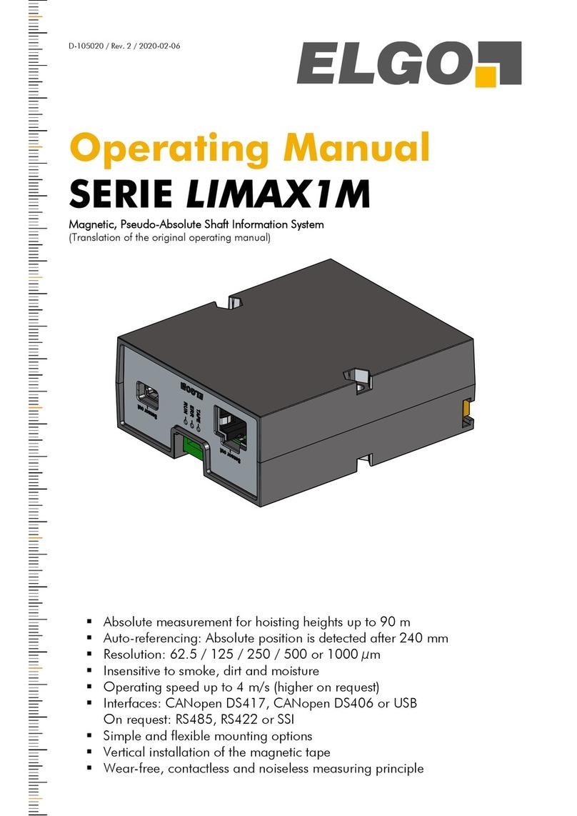
Elgo LIMAX33 CP-00 SERIES Instruction Manual

Safety Manual
SERIE LIMAX33 CP-00
Safe Magnetic Absolute Shaft Information System - STANDARD VERSION
(Original Safety Manual)
Easy and flexible installation
Replaces various electromechanical components in the elevator shaft
Resistant to dirt, smoke and humidity
Absolute position is always and directly available,
no referencing even after long power failure
Noiseless measuring principle
D-102840 / Rev. 11 / 2018-09-26

General
- 2 -
Publisher
ELGO Batscale AG
Föhrenweg 20
FL-9496 Balzers
Technical Support
+49 (0) 7731 9339 –0
+49 (0) 7731 2 13 11
Document- No.
D-102840
Document - Name
LIMAX33CP-00-MA-E_39-18
Article Number
799000808
Document- Revision
Rev. 11
Issue Date
2018-09-26
Copyright
© 2018, ELGO Electronic GmbH & Co. KG

General
- 3 -
Contents
1List of Figures..................................................................................... 5
2List of Tables ...................................................................................... 5
3General.............................................................................................. 7
3.1 Information on the Safety Manual.................................................................................. 7
3.2 References.................................................................................................................. 7
3.3 Explanation of Symbols ................................................................................................ 7
3.4 Statement of Warranties ............................................................................................... 9
3.5 Demounting and Disposal ............................................................................................ 9
4Safety ............................................................................................... 10
4.1 General Causes of Risk.............................................................................................. 10
4.2 Personal Protective Equipment..................................................................................... 10
4.3 Conventional Use...................................................................................................... 11
5Transport and Storage .................................................................... 12
5.1 Safety Instructions for Transport, Unpacking and Loading ............................................... 12
5.2 Handling of Packaging Material.................................................................................. 12
5.3 Inspection of Transport............................................................................................... 12
5.4 Storage.................................................................................................................... 12
6Product Features .............................................................................. 13
6.1 Functional principle ................................................................................................... 13
7Technical Data ................................................................................. 14
7.1 Identification............................................................................................................. 14
7.2 Dimensions of LIMAC33 CP-00 .................................................................................. 16
7.3 Technical Data LIMAX33 CP-00.................................................................................. 17
8Constraints for Use (Safety requirements for integration) ............. 18
9Type Designation ............................................................................. 22
10 Installation and First Start-Up......................................................... 23
10.1 Operating Area......................................................................................................... 23
10.2 Check of Safety Relevant Configuration........................................................................ 24
10.3 Mechanical Installation .............................................................................................. 24
10.4 Electrical Installation .................................................................................................. 24
11 Operation modes and Commissioning............................................ 33
11.1 Operation Modes...................................................................................................... 33
11.2 Manual Learning of the Floor Table............................................................................. 40
11.3 Automatic Learning of the Floor Table.......................................................................... 44
11.4 Reentering of Teach Mode, Sub-Mode “Manual” .......................................................... 50
11.5 Reentering of Teach Mode, Sub-Mode „Auto“............................................................... 51
11.6 Adjustments.............................................................................................................. 51

General
- 4 -
12 During Operation ............................................................................ 53
12.1 Triggering the Safety Functions.................................................................................... 53
12.2 The Error Level and Error Codes.................................................................................. 53
12.3 The Fault Register...................................................................................................... 56
12.4 Testing of the OC- Relays........................................................................................... 56
12.5 Testing of the eSGC-actuator...................................................................................... 56
12.6 LED Signals .............................................................................................................. 57
13 Safety Functions ............................................................................... 58
13.1 Safety Function Configuration ..................................................................................... 58
13.2 Safety Functions after Commissioning .......................................................................... 58
13.3 Safety Functions during Commissioning ....................................................................... 71
13.4 Safety Functions before Commissioning ....................................................................... 72
14 Configured/settable Parameter and Features ................................ 73
14.1 Configuration ........................................................................................................... 73
14.2 Settable Parameters ................................................................................................... 78
15 Initial and Annual Examination ...................................................... 79
15.1 System Restart........................................................................................................... 79
15.2 Magnetic Tape.......................................................................................................... 79
15.3 Software Identification................................................................................................ 79
15.4 Set of Configuration .................................................................................................. 79
15.5 Interference Suppression Measures .............................................................................. 79
15.6 Verification of the Floor Table ..................................................................................... 80
15.7 Check of Safety Functions........................................................................................... 80
16 Functional Safety ............................................................................. 83
16.1 Safety Parameters...................................................................................................... 83
16.2 Demands of EN 61508-2, Annex D2........................................................................... 85
16.3 Safety Requirements for the Integration of the System ..................................................... 86
17 Disturbances .................................................................................... 87
17.1 Fault Clearance ........................................................................................................ 87
18 Repairs / Maintenance .................................................................... 88
19 Replacing Components .................................................................... 89
19.1 Replacing Magnetic Tapes.......................................................................................... 89
19.2 Replacing the LIMAX33 CP-00.................................................................................... 89
20 Cleaning........................................................................................... 90
21 Accessories....................................................................................... 90
22 Index ................................................................................................ 92

General
- 5 -
1List of Figures
Figure 1: Example of a type label for identification of the sensor ................................................................. 14
Figure 2: Example of an info label on the housing with a specific system configuration ................................. 14
Figure 3: Example of an info sheet for the documentation of the installation with a specific system configuration
............................................................................................................................................................. 15
Figure 4: Dimensions of the sensor........................................................................................................... 16
Figure 5: Values for L and R of trip coil ..................................................................................................... 21
Figure 6: View on the top- and bottom-side of LIMAX33 CP-00 with eSGC.................................................. 25
Figure 7: Pin assignment eSGC connector (mechanical data according to IEC 61076-2-101) ...................... 25
Figure 8: Installation circuit diagram of LIMAX33 CP-00 (maximum configuration) ....................................... 28
Figure 9: Installation circuit diagram of LIMAX33 CP-00 (minimum configuration)........................................ 29
Figure 10: One SR and one door side ...................................................................................................... 30
Figure 11: One SR and two door sides ..................................................................................................... 30
Figure 12: eSGC actuator connected to a blocking device on the speed governor (remote tripping) .............. 31
Figure 13: Operation modes overview...................................................................................................... 34
Figure 14: Flow of events in teach mode .................................................................................................. 40
Figure 15: CANopen learning of double sided floors ................................................................................. 43
Figure 16: Flow of events in teach mode auto ........................................................................................... 45
Figure 17: Time-saving flow of events in teach mode auto ......................................................................... 47
Figure 18: Automatic learning of double sided floors ................................................................................. 49
Figure 19: LED´s on the upper side of the sensor in case of eSGC –Version ............................................... 57
Figure 20: ETSL-Curves ........................................................................................................................... 61
Figure 21: Conditions for door bridging and UCM .................................................................................... 64
Figure 22: Positions of inspection and stopping system limits in case of short head/pit and in case of head/pit-
clearance............................................................................................................................................... 66
Figure 23: Relations to the lower reference position ................................................................................... 69
Figure 24: Relations to the upper reference positions ................................................................................. 70
2List of Tables
Table 1: Connections PIO and SCA-Cable ............................................................................................... 26
Table 2: eSGC-Connector (only for versions with eSGC) ............................................................................ 26
Table 3: Floor Sensor plugs ..................................................................................................................... 27
Table 4: Earthing lug .............................................................................................................................. 27
Table 5: Safety output states in pre-commissioning mode (see also 13.4) ................................................ 35
Table 6: Safety output states in teach mode or teach auto mode when reference positions are available ........ 36
Table 7: Floor table as stored in CP in case of double sided floors.............................................................. 43
Table 8: Floor table as stored in CP in case of double sided floors learned automatically.............................. 49
Table 9: Error -level ................................................................................................................................ 53
Table 10: Error codes ............................................................................................................................. 54
Table 11: Errors concerning nonvolatile stored data .................................................................................. 55
Table 12: Meaning of the LEDs................................................................................................................ 57
Table 13: Safety Functions after Commissioning ........................................................................................ 58
Table 14: Distance to assumptive buffer dependent on moving direction and mode ..................................... 60
Table 15: OC reaction if position is higher than upper inspection limit ........................................................ 68
Table 16: OC reaction if position is lower than lower inspection limit .......................................................... 68
Table 17: Safety functions during commissioning....................................................................................... 71
Table 18: Safety functions before commissioning....................................................................................... 72
Table 19: configuration parameter concerning speeds ............................................................................... 73
Table 20: configuration parameter for ETSL-Curve .................................................................................... 74
Table 21: configuration parameter for offsets of stopping system limits ........................................................ 74
Table 22: configuration features for Safety functions .................................................................................. 75
Table 23: dependency “enabled safety functions” => needed actuators/relay contacts ................................ 76
Table 24: Behavior of UCM and overspeed final tripping dependent on the concerning configuration features 77
Table 25: Settable parameters ................................................................................................................. 78
Table 26: Required and achieved SIL........................................................................................................ 83
Table 27: Safe failure fraction, HFT and Type of the subsystems ................................................................. 84

General
- 6 -
Table 28: Diagnostics Test Interval (DTI) of the subsystems ......................................................................... 84
Table 29: Demands of 61508 ................................................................................................................. 85
Table 30: Calculation of Dfor the entire system ....................................................................................... 86
Table 31: Accessories ............................................................................................................................. 90

General
- 7 -
3General
3.1 Information on the Safety Manual
This manual contains important information regarding the handling of the device. For your own safety and op-
erational safety, please observe all safety warnings and instructions.
Precondition for safe operation is the compliance with the specified safety and handling instructions. Moreover,
the existing local accident prevention regulations and the general safety rules at the site of operation have to be
observed.
Please read the operating manual carefully before starting to work with the device! It is part of the product and
should be kept close to the device and accessible for the staff at any time. The illustrations in the manual are for
better demonstration of the facts. They are not necessarily to scale and can slightly differ from the actual design.
3.2 References
/LIMAX33CP-00-MI/ Mounting Instructions for LIMAX33 CP-00 with installation kit LIMAX S-RMS2
https://www.elgo.de/fileadmin/user_upload/pdf/manual/lift/LIMAX33CP-00-MI-E.pdf
/CiA DR303-3/ CiA Draft Recommendation 303, Part 3: Indicator specification; CAN in Automation
/EN81-20/ Safety rules for the construction and installation of lifts
/EN81-21/ Safety rules for the construction and installation of lifts
3.3 Explanation of Symbols
Special notes in this manual are characterized by symbols.
The notes are introduced by signal words which express the magnitude of danger.
Please follow this advice and act carefully in order to avoid accidents and damage and injuries.
Warning notes:
DANGER!
This symbol in connection with the signal word “Danger” indicates an immediate danger for
the life and health of persons. Failure to heed these instructions can result in serious damage
to health and even fatal injury.
WARNING!
This symbol in connection with the word „Warning” means a possibly impending danger for
the life and health of persons. Failure to heed these instructions can result in serious damage
to health and even fatal injury.
CAUTION!
This symbol in connection with the signal word “Caution” indicates a possibly dangerous
situation. Failure to heed these instructions can lead to injuries or damage of property.
Special safety instructions:
DANGER!
This symbol in connection with the signal word “Danger” indicates an immediate danger for
the life and health of persons due to voltage. Failure to heed these instructions can result in
serious damage to health and even fatal injury. The operations may only be carried out by a
professional electrician.

General
- 8 -
Tips and recommendations:
NOTE!
…points out useful tips and recommendations as well as information for an efficient and
trouble-free operation.
References:
() This symbol marks a reference to a chapter of this document
() This symbol marks a reference to chapter of another document

General
- 9 -
3.4 Statement of Warranties
The statement of warranties is enclosed separately in the sales documents.
Guarantee
The producer guarantees the functional capability of the process engineering and the selected parameters. The
period of warranty is one year and begins with the date of delivery.
3.5 Demounting and Disposal
Unless acceptance and disposal of returned goods are agreed upon, demount the device considering the safety
instructions of this manual and dispose it with respect to the environment.
Before demounting:
Disconnect the power supply and secure against re-start. Then disconnect the supply lines physically and dis-
charge remaining energy. Remove operational supplies and other material.
Disposal:
Recycle the decomposed elements:
Metal components in scrap metal
Electronic components in electronic scrap
Recycle plastic components
Dispose the remaining components according to their material consistence
CAUTION!
Wrong disposal causes environmental damages!
Electronic scrap, electronic components, lubricants and other auxiliary materials are
subject to special refuse and can only be disposed by authorized specialists!
Local authorities and waste management facilities provide information about environmentally sound disposal.

Safety
- 10 -
4Safety
CAUTION!
Please read the operating manual carefully, before using the device! Observe the installa-
tion instructions!
Only start up the device if you have understood the operating manual.
The operating company is obliged to take appropriate safety measure.
The initial operation may only be performed by qualified and trained staff.
Selection and installation of the devices as well as their embedding into the controlling
system require qualified knowledge of the applicable laws and normative requirements on
the part of the machine manufacturer.
4.1 General Causes of Risk
This chapter gives an overview of all important safety aspects to guarantee an optimal protection of employees
and a safe and trouble-free operation.
Non-observance of the instructions mentioned in this operating manual can result in hazardous situations.
4.2 Personal Protective Equipment
Employees have to wear protective clothing during the installation of the device to minimize danger of health.
Therefore:
Change into protective clothing before performing the works and wear them throughout the process.
Additionally observe the labels regarding protective clothing in the operating area.
Protective clothing:
PROTECTIVE CLOTHING
… is close-fitting working clothing with light tear strength, tight sleeves and without distant
parts. It serves preliminarily for protection against being gripped by flexible machine parts.
Do not wear rings, necklaces or other jewelry.
PROTECTIVE GLOVES
…for protecting the hands against abrasion, wear and other injury of the skin.
PROTECTIVE HELMET
…for protection against injuries of the head.

Safety
- 11 -
4.3 Conventional Use
The product described in this manual was developed to execute safety-related functions as a part of an entire
assembly or machine. It is the responsibility of the manufacturer of a machine or installation to ensure the prop-
er operation of the system. The ELGO-device is conceived only for the intended use described in this manual.
The ELGO length measuring system LIMAX33 CP-00 serves only to measure lengths in lift
systems and to fulfill the required safety functions (described in chapter 13).
CAUTION!
Danger through non-conventional use!
Non-intended use and non-observance of this operating manual can lead to dangerous sit-
uations.
Therefore:
Only use the device as described
Strictly follow the instructions of this manual
Avoid in particular:
Remodeling, refitting or changing of the construction or single components with the
intention to alter the functionality or scope of the device.
Claims resulting from damages due to non-conventional use are not possible.
Only the operator is liable for damages caused by non-conventional use.

Transport and Storage
- 12 -
5Transport and Storage
5.1 Safety Instructions for Transport, Unpacking and Loading
CAUTION!
Transport the package (box, palette etc.) professionally. Do not throw, hit or fold it.
5.2 Handling of Packaging Material
Notes for proper disposal: 3.5
5.3 Inspection of Transport
Check the delivery immediately after the receipt for completeness and transport damage.
In case of externally recognizable transport damages:
Do not accept the delivery or only accept under reserve.
Note the extent of damages on the transportation documents or delivery note.
File complaint immediately.
NOTE!
Claim any damage immediately after recognizing it. The claims for damage must be filed in
the lawful reclaim periods.
5.4 Storage
Store the device only under the following conditions:
Do not store outside
Keep dry and dust-free
Do not expose to aggressive media
Protect from direct sun light
Avoid mechanical shocks
Storage temperature (7) needs to be observed
Relative humidity (7) must not be exceeded
Inspect packages regularly if stored for an extensive period of time (>3 months)

Product Features
- 13 -
6Product Features
LIMAX33 CP-00 is a magnetic tape-based shaft information and safety system which covers:
Several safety functions named in the EN81-20/21
The requirements regarding cab position measurement (e.g. as information for lift control)
Non safety relevant functions like door zone indication for emergency release
The magnetic measuring principle makes the sensor insensitive even to black smoke and splash water. Magnetic
tape and sensor can be mounted easily.
ADVANTAGES
The drastic reduction of the components offers significant cost advantages. Time for installation and mainte-
nance is reduced significantly. A possible troubleshooting is also simplified, especially since the electronic pro-
vides diagnostic options.
LIMAX33 CP-00 is as well suitable for serial production with new installations as for upgrading existing elevator
systems.
6.1 Functional principle
The tape carries the unique positioning information as a magnetic code. It is installed free hanging in the eleva-
tor shaft by use of a mounting kit. The LIMAX33 CP-00 is mounted to the elevator car. While the actual meas-
urement is contactless the tape must be kept within a maximum distance to the sensor head. Therefore, the tape
is guided along theLIMAX33 CP-00 by use of the polymer tape guide which is an integral component of the
sensor head.
The magnetic measurement principle is extremely robust. Dust, dirt and humidity do not affect the measurement
in any way. Also, smoke and even higher temperatures have no influence on the measuring quality. Further the
tape is robust enough to withstand the harsh conditions in elevator shafts.

Technical Data
- 14 -
7Technical Data
7.1 Identification
7.1.1 Type Label
The type label serves for the identification of the unit. It is located on the housing of the sensor and gives the
exact type designation (= order reference, see 9) with the corresponding part number. Furthermore, the type
label contains a unique, traceable device number, the production date as well as the hardware and software
versions. When corresponding with ELGO always indicate this data.
Figure 1: Example of a type label for identification of the sensor
7.1.2 Info Label and Info Sheet
Each system is designed for a customer specified configuration (14.1). For subsequent transparency of the
respective configuration it is strongly recommended to attach an info sheet Figure 3 with all important settings to
the documentation of the installation. A label with the configuration ID (Figure 2) is attached on the device
housing as well. Additionally, an info sheet with all configuration information should be attached to the elevator
system (e. g. in the shaft).
Figure 2: Example of an info label on the housing with a specific system configuration
Prod.Date:
Version:
ELGO Part No.:
Serial No.: 000000 XX.XXXX MADE IN LIECHTENSTEIN
000000000
LIMAX3CP-00-030-1000-CO0T-1-0
P-0001/250k/0/1
HW: XX.X / SW: X.XXXX
Type Designation (9):
Designation 1
Designation 2

Technical Data
- 15 -
Tripping speeds
Rated speed 1000 mm/s
Pre-tripping speed 1150 mm/s
Final tripping speed 1300 mm/s
Pre-tripping speed teach 700 mm/s
Final-tripping speed teach 1000 mm/s
Pre-tripping speed inspection 600 mm/s
Final-tripping speed inspection 800 mm/s
Features
Trip direction of eSGC („BOTH“/„Only DOWN“) BOTH
UCM acts („only OC“ / „eSGC and OC“) eSGC and OC
Configuration Data
Limit switch offsets (with reference to the shaft ends)
Upper pre-triggered stopping system limit 1200 mm
Lower pre-trigegred stopping system limit 0 mm
Deceleration control
Deceleration a 1.2 m/s2
Delay of brake 200 ms
Buffer speed 600 mm/s
Upper offset 0 mm
Lower offset 0 mm
Safety functions(enabled/disabled)
Door (bridging + UCM) enabled
Final limit switches enabled
Deceleration control enabled
Over speed pre-tripping enabled
Over speed final-tripping enabled
Over speed teach pre-trip. enabled
Over speed teach fin.-trip. disabled
Working platform disabled
Inspection functions (global) enabled
Over speed insp. fin.-trip. enabled
Upper pre-trigg. stop. System enabled
Lower pre-trigg. stop. System disabled
Actuators (enabled/disabled)
OC enabled
eSGC enabled
SR1 enabled
SR2 disabled
Teach featues (enabled/disabled)
Auto teach disabled
Auto adjust disabled
Figure 3: Example of an info sheet for the documentation of the installation with a specific system configuration
7.1.3 Configuration of the Device
The customer has the choice. He may either order an already configured device at ELGO (7.1.3.2), or he
orders a blank device and does the configuration on site.
7.1.3.1 Configuration on site
It is possible to order a blank device at ELGO and do the configuration on site.
In this case same label applies as described in Figure 2, but with blank configuration ID. A sticker with the con-
figuration ID has to be attached onto the info label).
The blank device will be configured with the values / features via CAN-Bus. These can be found on the infor-
mation sheet (Figure 3) in the documentation of the installation. For example, the lift control can be used as
input/display unit for the configuration. In addition to the actual configuration information, the CRC from the
info sheet must be sent to the device.
The LIMAX33 CP-00 will accept the configuration only if the CRC fits. This prevents configuration errors due to
incorrect input or incorrect transmission. After the LIMAX33 CP-00 accepted the configuration it is fixed and it
cannot be changed anymore.
If lift control shall be used as input/display- unit the corresponding features must be implemented.
refer also to CANopen specification

Technical Data
- 16 -
7.1.3.2 Configuration at ELGO
It is possible to order a configured device at ELGO on own expense. In this case, all labels and sheets will be
provided.
7.2 Dimensions of LIMAC33 CP-00
Figure 4: Dimensions of the sensor

Technical Data
- 17 -
7.3 Technical Data LIMAX33 CP-00
LIMAX33 CP-00 (Standard version)
Mechanical Data
Measuring principle
Absolute
Repeat accuracy
±1 increment
System accuracy in µm at 20°C
±(1000 + 100 x L) L = measuring length in meters
Distance sensor / magnetic tape
the correct distance is guaranteed by guidance
Basic pole pitch
8 mm
Sensor housing material
aluminum
Sensor housing dimensions
L x W x H = 354 x 136 x 54 mm
Necessary magnetic tape
AB20-80-10-1-R-D-15-BK80
Maximum measuring length
260 m
Connections
2 outlets with open wire ends for PIO and SCA cables
(plug connectors on request)
M12 4 pole male for eSGC; according to ICE61067-2-101
Sensor cable (PIO, SCA)
standard length: 3.0 m (others on request)
Weight
approx. 1400 g without cable; cable: approx. 60 g per meter
Electrical Data
Supply voltage
18 ... 30 VDC (stabilized). A SELV/PELV power supply must be used
Residual ripple
< 100 mV
DZO rating
+ 24 VDC −20 %, max.200 mA (push-pull)
Reverse polarity protection
integrated
Power input
max. 600 mA at 24 VDC
Interfaces
CAN: CANopen DS406 or DS417 (others on request)
Digital input voltage
18 … 30 VDC for high level; open for low level
Relay contact rating
OC, SR1, SR2
0 … 230 VAC (max 250 VAC), max. 2 A; or
24 VDC (max. 30 VDC), max. 1 A; or 110 VDC, max. 250 mA;
each with a resistive/inductive load with L/R < 40 ms
Rating for external supply
of SGC-actuator
24 VDC, min. 18 V; max. 30 V; constraints for connected trip coil to be
observed (refer also to chapter8, topic 23 and 24
Environmental Conditions
Storage temperature
−25 … +85° C
Operation temperature
−20 … +65° C
(−25 … +85° C on request)
Humidity
max. 95 %, non-condensing
Protection class
IP54 (according to EN60529), higher on request
Interference emission / immunity
EN 12015 / EN 12016
Vibration / shock resistance
EN 60068-2-6 / EN 60068-2-27, EN 60068-2-29
Others
Maximum operating time
20 years
Safety relay contact reaction time
< 55 ms
Solid state contact (eSGC) reaction
time
< 45 ms

Constraints for Use (Safety requirements for integration)
- 18 -
8Constraints for Use (Safety requirements for integration)
The general constraints for use of LIMAX33 CP-00 are listed here:
1. Configuration of LIMAX33 CP-00 and the elevator (where it is installed) must fit. The configuration is not-
ed on the info sheet 7.1.2. It cannot be changed after it has once been programmed to the device. The
following topics must be taken into consideration when defining the configuration:
a. It is possible to disable all safety functions related to inspection and/or “EN81-21”- state in com-
bination
1
. In this case neither upper resp. lower “pre-triggered stopping system”, nor upper resp.
lower inspection limit switch nor overspeed inspection (pre- /final-tripping) are performed by the
LIMAX33 CP-00. In this case these safety functions must be implemented by other means (if nec-
essary) outside of the scope of LIMAX33 CP-00.
b. All actuators necessary for the safety functions which are enabled, must be enabled in the config-
uration and connected to the safety circuit resp. an external braking element for eSGC following
10.4.3, 10.4.4, 10.4.5 and 10.4.8 . Section 14.1.3 shows an overview over the
actuators necessary for the single safety functions.
c. In case of upper resp. lower “pre-triggered stopping system” = DISABLED, it must be ensured that
there is
either ample survival space for a man on the car roof resp. in the shaft pit even if the car is
on the highest resp. lowest possible position.
or survival space for a man on the car roof resp. in the shaft pit is implemented by other
means outside of the scope of LIMAX33 CP-00.
The combination upper “pre-triggered stopping system” = ENABLED and “trip direction = only
down” is forbidden. It is also prevented by the software of the LIMAX33 CP-00 that this combina-
tion is programmed.
d. If all safety functions related to inspection and/or “EN81-21”- state in combination are disabled,
also the upper and lower inspection limit switches are disabled. In this case must be ensured that
EN81-21 §5.5.3.4§5.7.3. resp. EN81-20 §5.12.1.5.2.1 g) are implemented by other means
outside of the scope of LIMAX33 CP-00.
e. In case of upper or lower “pre-triggered stopping system” are enabled (not disabled) it is recom-
mended not to disable the safety function “overspeed inspection final tripping”. If “overspeed in-
spection final tripping” is disabled while upper or lower “pre-triggered stopping system” is ena-
bled, the user must ensure the worst-case speed for calculation of braking distance for pre-
triggered stopping system (refer to point n) be other means.
f. In case safety function “ETSL” = DISABLED, it must be ensured that
either ETSL is not needed because the buffers are designed for nominal speed of the lift
or safety function ETSL is implemented by other means outside of the LIMAX33 CP-00 scope
g. In case safety function “final limit switches” = DISABLED, it must be ensured that safety function
“final limit switches” is implemented by other means outside of the scope of LIMAX33 CP-00
h. Safety function “door bridging” and “UCM” can only be disabled in combination. “door bridging”
/ “UCM” = DISABLED, neither door bridging nor UCM will be performed by LIMAX33 CP-00
i. In case safety function “over-speed final-tripping” = DISABLED, it must be ensured that
this safety function is implemented by other means outside of the scope of LIMAX33 CP-00
(usually by a conventional speed governor). In case safety function “over-speed final-tripping” =
ENABLED, safety function “over-speed final-tripping” will only fulfill EN81-20 §5.6.2.2.1.1a.) in
case the eSGC actuator is connected to a suitable (electronic triggered) safety gear. In case
“over-speed final-tripping” = ENABLED and “trip direction” = “only down”, it must be ensured
that the safety function “overspeed (final tripping)” is either not needed in upwards direction (may
be due to the construction of the lift), or that “over speed (final tripping)” in upwards direction is
secured by other means (outside the scope of LIMAX33 CP-00).
j. The nominal speed of the LIMAX33 CP-00 must fit with the nominal speed of the lift
k. Pre-tipping and final tripping speed must be chosen in compliancy with EN81-20 with respect to
the nominal speed.
1
Some, but not all of the „inspection/ EN81-21-state“- safety functions can also disabled individually

Constraints for Use (Safety requirements for integration)
- 19 -
l. The speed limited by safety function “inspection overspeed (final tripping)” can be used to ensure
the worst-case speed for the determination of the braking distance for “pre-triggered stopping sys-
tem” (see point n)
m. The inspection speed is normally limited by lift control. LIMAX33 CP-00 supervises this limitation
by safety function “inspection overspeed (pre-tripping)”. The tripping speed should be chosen so
that is
big enough, so that this safety function does not trip by fail if the car travels in an inspection
trip with normal inspection speed.
small enough so that - in case of a too fast inspection trip by failure - this safety function
has the chance to stop the car by machine brake via safety circuit before the car is stopped
by safety gear (tripping of safety gear cause by “inspection overspeed (final tripping)”
n. The offset of limit positions for upper resp. lower “pre-triggered stopping systems” must be chosen
in such a way, that ample survival space for a person on car roof resp. in the shaft pit is ensured
after the sequence car stopped safety gear tripped limit positions for upper resp. lower “pre-
triggered stopping systems” have been over travelled. Braking distance under worst case condi-
tions must be considered when defining the offsets. Braking distance depends on actual speed
(due to worst case assumption, refer to l and e ), reaction time of CP (see point 8. be-
low) and delay and the deceleration of the safety gear.
o. The feature “trip direction” = “only down” may be used if the safety gear is only unidirectional. In
this case all safety function using the eSGC as an actuator will trip only in downwards direction.
Therefore, the combination “trip direction” = “only down” is forbidden in combination with some
of the safety functions (refer also to c and p). Other safety functions can only be used under
constraints if “trip direction” = “only down” (refer to i and q )
p. LIMAX33 CP-00 is able to fulfill EN81-20 §5.2.6.4.3.1 b.), but only if safety function “working
platform” is enabled. The combination “working platform is enabled” and “trip direction = only
down” is forbidden. It is also prevented by the software of the LIMAX33 CP-00 that this combina-
tion is programmed.
q. If “door bridging / UCM” is enabled and “trip direction = only down” is enabled, tripping of
UCM will act the braking element connected to the eSGC actuator (normally the safety gear) only
in downwards direction. If UCM trips in upwards direction only OC opens (additional to SR1 and
SR2). In this case it must be either ensured that it is in compliancy with the EN81-20 that UCM
can be fulfilled with the machine brake in upwards direction or “UCM in upwards direction”must
be secured by other means (outside the scope of LIMAX33 CP-00).
r. If “UCM only OC” is enabled, only OC will open (additional to SR1 and SR2). In this case the
machine brake is the braking element for the safety function “UCM”. Therefore, the machine
brake must be a certified safety brake in order to fulfil EN81-20 §5.6.7.
s. Safety function “over speed teach (pre-tripping)” is intended to be used as a substitute for ETSL
during teach mode. If this safety function is not needed, it may be disabled. If it is needed, the
tripping speed for “over speed teach (pre-tripping)” should not be higher than the buffer speed.
t. Safety function “over speed teach (final-tripping)” is intended to be used for general additional
safety (without a reference to the EN81-20). It may be disabled if not desired.
u. The Parameter “a”, “Vbuf”, “tdel“ and “offset” must be adjusted in such a way, that – in case ETSL
trips - the car hits the buffer surface with a speed not bigger the buffers are designed for.
v. The OC actuator must be enabled in any case
2. To prevent any short-circuit between the 24 VDC UP/DOWN signals of the inspection control or the
24 VDC “EN21-21” signal of the electrical safety device and adjacent circuits, the requirements of EN81-
50§5.15 must be met.
3. The technical data (mechanical, electrical and environmental) concerning the LIMAX33 CP-00 - sensor as
defined in chapter 7.3 are valid for constraints for use.
4. The technical data (mechanical, magnetically and environmental) concerning the magnetic tape as de-
fined in a separate data sheet are valid for constraints for use.
5. The value of fuse protecting the safety circuit must be in compliancy with the electrical data of safety circuit
defined in chapter 7.3
6. The value of fuse protecting the eSGC circuit must be in compliancy with the electrical data of eSGC-
circuit defined in chapter 7.3
7. Operation height: up to 2000 m above sea level

Constraints for Use (Safety requirements for integration)
- 20 -
8. The worst case reaction times of relay contacts OC, SR1 and SR2 when a safety function is triggered is
<55 ms and concerning the eSGC <45 ms.
9. Constraints for Installation of magnetic tape according to its instruction manual must be observed
10. A tape presence detector securing the risk of demolition of the magnetic tape must be integrated into the
safety circuit, see also the installation schemes (Figure 8, Figure 9and Figure 12)
11. The OC-actuator must always be integrated in the safety circuit, see Figure 8 and Figure 9.
12. The eSGC-actuator must be connected to an electromechanical braking element following the idle current
principle.
13. The inspection controls signals must be connected following Figure 8.
14. The earthling lug on the LIMAX33 CP-00 must be connected to protection earth.
15. The inductivities switched by the actuators (examples: contactors at the end of safety circuit switched by
OC, SR1 or SR2; tripping coil of electronic safety gear - switched by eSGC) must be equipped by suitable
interference suppression measures; e.g. recovery diodes for DC-circuits; RC-circuits for AC-circuits.
16. The safety functions over speed final tripping, pre-triggered stopping system and ETSL must fulfill SIL 3
and therefore the PFHD of the whole functional chain must be smaller than 100 FIT. Concerning the PFHD
capability of the LIMAX33 CP-00 (16.1).
17. The braking element connect to the eSGC actuator may be:
a) an electronic triggered safety gear,
b) a conventional safety gear triggered by a conventional speed governor, which in turn is triggered
via the remote triggering of the LIMAX33 CP-00
c) another braking element the safety gear or the machine brake (e.g. a rope gripper)
The braking element following a.) can always be chosen, no matter if safety function “over speed final
tripping” UCM, pre-triggered stopping system or working platform should be fulfilled via the eSGC-
actuator.
The braking element following b.) can be chosen, no matter if safety functions “UCM”, “pre-triggered
stopping system”or “working platform”should be fulfilled via the eSGC-actuator.
Overspeed (final tripping) following EN81-20 §5.6.2.2.1.1a.) is normally fulfilled by the conventional
speed governor in this case.
The braking element following c.) can only be used for the safety function “UCM”. The safety functions
“working platform”or “pre-triggered stopping system”can only be fulfilled by a brake acting on the
rails (due to EN81-20).
18. The CAN bus is not intended to be used for safety relevant purposes.
19. After commission, the floor table must be checked before the lift is allowed to be released for public use.
20. A power cycle or a reset must be d to the LIMAX33 CP-00 at least once per year.
21. The reaction time of the electronic safety gear (resp. other braking element on eSGC) is in the responsibil-
ity of the user. In the technical data 7.3, “Solid state contact (eSGC) reaction time” a time of 45 ms is
defined. This concerns to the time from appearance of a hazardous speed until solid state switch is
opened and therefore voltage on trip is switched off. The reaction time of the electronic safety gear is the
time from opening of the solid state switch until braking force is present. The reaction time of the electron-
ic safety gear consists of an electrical and mechanical portion. Concerning the electrical portion refer also
to topic 23.d.
22. It must be ensured that the eSCG-braking element trips (goes to safe state) if the voltage on its trip coil
amounts to 2 V or below.
23. The trip coil of the eSGC-braking element connected to the eSGC-actuator must fulfill the following con-
ditions (refer also to Figure 5), Remark: if resistance or inductivity of the wire from eSCG-connector to the
trip coil have a relevant magnitude, this must also be taken into account
a. L < 1.5H
b. Current consumption < 1A => R > 24Ohm @24V (the eSGC –actuator is secured inside the
CP with a 1A self-resetting polyfuse)
c. L/R > 1ms (recommended): for L/R << 1ms there is a danger that the braking element would
fall during the test of the eSGC-actuator, refer also to chapter 12.5.
d. L/R < 10 ms (recommended). The L/R influences –beside the mechanical construction –the time
for the braking element to fall. A big L/R causes a slower falling of the current through the coil af-
ter the voltage has been switched off. The current again influences the holding force of the coil,
refer also to topic 21.
Table of contents
Other Elgo Measuring Instrument manuals
