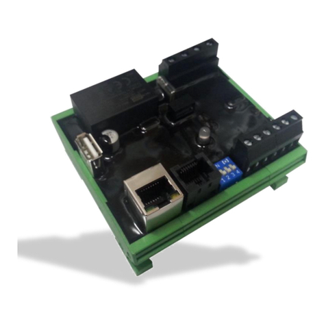
elgris ZERO Export User manual

ZERO Export
“Universal ZERO export controller”
Manual
ZERO and ZEROplus
Version 1.3

Version: 5. August 2019 19:37
www.elgrispower.com
Page 2 of 23
Table of Contents
1. INTRODUCTION___________________________________________________________________________ 4
2. INSTALLATION____________________________________________________________________________ 5
2.1 Safety instructions____________________________________________________________________ 5
2.2 Device overview______________________________________________________________________ 5
2.3 Pin description _______________________________________________________________________ 6
2.4 Wiring diagram ______________________________________________________________________ 6
2.5 ZEROplus ___________________________________________________________________________ 7
2.5.1 Electrical rating ____________________________________________________________________ 7
2.5 RS 485 pin out _______________________________________________________________________ 8
2.6 Dipswitches _________________________________________________________________________ 8
3COMMISSIONING__________________________________________________________________________ 9
3.1 First time power on ___________________________________________________________________ 9
4GRAPHICAL USER INTERFACE ________________________________________________________ 10
4.1 Overview __________________________________________________________________________ 10
4.1.1 Header __________________________________________________________________________ 10
4.1.2 Main area ________________________________________________________________________ 11
4.1.3 Daily chart _______________________________________________________________________ 11
4.2 Inverter settings_____________________________________________________________________ 12
4.3 System settings _____________________________________________________________________ 13
4.3.1 Change the static IP settings _________________________________________________________ 13
4.3.2 Change the time zone ______________________________________________________________ 13
4.3.3 Setting the serial baud rate __________________________________________________________ 14
4.3.4 Broadcast ________________________________________________________________________ 14
4.3.5 SMA Smart Meter _________________________________________________________________ 14
4.3.6 SMA turbo _______________________________________________________________________ 14
4.3.7 VT value _________________________________________________________________________ 14
4.3.8 CT value _________________________________________________________________________ 14
4.3.9 Setpoint _________________________________________________________________________ 15
4.4 elgris cloud _________________________________________________________________________ 16

Version: 5. August 2019 19:37
www.elgrispower.com
Page 3 of 23
4.5 Live chart __________________________________________________________________________ 17
4.6 Data logger_________________________________________________________________________ 18
4.7 Performance________________________________________________________________________ 18
4.8 ZEROplus __________________________________________________________________________ 19
5ADJUSTING THE PID SETTINGS_______________________________________________________ 20
5.1 Manual tuning ______________________________________________________________________ 20
5.2 Ziegler–Nichols method ______________________________________________________________ 21
6FIRMWARE UPDATE ___________________________________________________________________ 22
6.1. Introduction ________________________________________________________________________ 22
6.2 Connecting with the controller_________________________________________________________ 22
6.3 Start of the boot loader_______________________________________________________________ 22
6.4 Login ______________________________________________________________________________ 23
6.5 Select new firmware _________________________________________________________________ 23
6.6 Reset the controller__________________________________________________________________ 23

Version: 5. August 2019 19:37
www.elgrispower.com
Page 4 of 23
1. Introduction
Dear customer, thank you for purchasing this product. The ZERO export controller is the first
controller available on the market which can control up to 10 PV inverters with ZERO export
functionality. Further the ZERO can also act a general PV output controller by limiting the production.
The ZERO export controller has the following features
•Full 3 phase power measurements
•MODBUS RTU control
•MODBUS TCP control
•USB 2.0 flash drive support for data storage
•Multi-colour user LED for status information
•Integrated webserver for intuitive configuration and parametrisation
The following versions or modules are available:
•ZERO EXPORT
•MONITORING AND DATALOGGER
•POWER MANAGEMENT
•LOAD MANAGEMENT
This manual covers all versions. Version specific information is marked on version specific chapters.
Specializing in products for renewable energy, Diesel generators and hybrid power solutions, the
ZERO export offers the following features standard:
•Wide range power supply input from 85 - 265 VAC (50 - 60 Hz)
•Small footprint.
•Intuitive software.
•Wide temperature range of -40° –+85°.
•Industrial PUR protection coating for extra rugged environment.
•IP-68 on request.
If you have any questions or if something is unclear, you can contact us in several ways:
Per E-Mail : support@elgrispower.com
By Phone : +49 (0) 2423 9086501

Version: 5. August 2019 19:37
www.elgrispower.com
Page 5 of 23
2. Installation
2.1 Safety instructions
Before installing the product in the end-installation, ensure that the device is not damages during
transport and everything looks in a normal way.
All the connecting cables must not be bent or squeezed. This can result in malfunctions, short circuits
and defects in the device and/or sensor connected.
Make sure that cables are not damaged when drilling or bolting in place.
The module may only be commissioned after it has been installed contact-free in a casing. This
product generates high frequency. Never operate it in the vicinity of medical devices (e.g.
pacemakers) and/or medical equipment (e.g. in hospitals). Look for a suitable installation site.
2.2 Device overview
Before wiring the device, be sure that the voltage is switched off.
on
1234
1 2 3 4
5 6 7 8 9 10
RS-485
Ethernet
USB

Version: 5. August 2019 19:37
www.elgrispower.com
Page 6 of 23
2.3 Pin description
Voltage
input
Pin
Description
Minimum
Maximum
1
Phase 1 voltage input
85 Vac
250 Vac
2
Phase 2 voltage input
85 Vac
250 Vac
3
Phase 3 voltage input
85 Vac
250 Vac
4
Neutral input of voltage
0 Vac
Power input
5
K input current transformer L1
0 Aac
5 Aac
6
L input current transformer L1
0 Aac
5 Aac
7
K input current transformer L2
0 Aac
5 Aac
8
L input current transformer L2
0 Aac
5 Aac
9
K input current transformer L3
0 Aac
5 Aac
10
L input current transformer L3
0 Aac
5 Aac
Dipswitch
1
IP address selection
OFF = DHCP
ON = static
2
System frequency
OFF = 50 Hz
ON = 60 Hz
3
Single or Three phase
OFF = Three phase
ON = Single phase
4
Internal use only
OFF = Default
2.4 Wiring diagram
on
1 2 3 4
L1
L2
L3
N
L
K
KL
GRID
LOAD
N
Please read the manual of the used inverter to check wiring scheme.
Note: Some inverters may need additional hardware

Version: 5. August 2019 19:37
www.elgrispower.com
Page 7 of 23
2.5 ZEROplus
on
1234
The ZEROplus is a ZERO controller equipped with 4 dry contacts to control external loads before
shunting the solar output.
Channel
Pin
Electrical limit
1
11 and 12
1 A at 250 VAC, 1 A at 30 VDC, resistive load
2
13 and 14
1 A at 250 VAC, 1 A at 30 VDC, resistive load
3
15 and 16
1 A at 250 VAC, 1 A at 30 VDC, resistive load
4
17 and 18
1 A at 250 VAC, 1 A at 30 VDC, resistive load
2.5.1 Electrical rating
11 12 13 14
18 17 16 15

Version: 5. August 2019 19:37
www.elgrispower.com
Page 8 of 23
2.5 RS 485 pin out
Pin
Description
1
Not connected
2
RS-232 TX
3
RS-232 RX
4
RS-485 B (D-)
5
RS-485 A (D+)
6
GND
7
Not connected
8
Not connected
2.6 Dipswitches
Dipswitch
Description
OFF
ON
1
DHCP
Static IP
2
50 Hz
60 Hz
3
Three phase
Single phase
4
Not used must be OFF
2.7 LED status
The LED on board informs the user about the internal status.
LED colour
Meaning
Action
Off
No power or internal error
Contact support
Internal Error
Contact support
Date and time not set, no USB data
logging possible
Update date and time or check
internet connection for SNTP
Standby, no inverter online
Check inverter settings
Controller is throttling the PV
Normal operation
Power management active
Normal operation
Controller is not throttling PV
Normal operation

Version: 5. August 2019 19:37
www.elgrispower.com
Page 9 of 23
3 Commissioning
Before starting with the commissioning of the ZERO export controller all safety precautions must be
taken which apply to the rules in your country and general safety rules. Never work on a system with
a running generator or connected grid and short the output of the generator (when available) before
working on the power system.
Only a few settings are needed to commission the ZERO export controller.
Most important is the settings of the current transformer and the setpoint for the limitation of the
power.
3.1 First time power on
Follow the following steps when the system is first time being powered.
Set the dipswitches according to the settings required. Ensure that the IP address is known
when using DHCP.
Switch off the PV inverter, disconnect the PV inverter from the system and start the
controller by applying power to L1 and N in case you use a single-phase system or L1, L2 and
L3 with N for three phase systems. When the ZERO export unit is working properly, the LED is
blinking green or red / green flashing in case there is no internet connection, or the time
server could not be reached.
Connect to the embedded webserver by typing the default address 192.168.1.100 in a web
browser. When using DHCP type the local IP address given by the DHCP server.
On the Menu select Settings and then enable the checkbox “Advanced Settings” to adjust the
CT ratio. The CT ratio is defined as 1: value. For example, when you have a CT 5:200 the value
is 40.
When the CT ratio is changed the power readings on the overview page should match the
actual power. A positive value is consumption from the grid, a negative value means
exporting to the grid. When this is not correct, check the wiring of K and L of the CT.
Detailed readings can be got by typing 192.168.1.100/Meter
Switch on the DC side of the PV system to commission the PV inverters. The steps to add an
inverter to the system is explained on page 9.

Version: 5. August 2019 19:37
www.elgrispower.com
Page 10 of 23
4 Graphical User Interface
The ZERO export controller includes a webserver to adjust the system parameters and see the status
of the system.
By default, the webserver can be reached by typing the IP address 192.168.1.100 in a web browser.
Supported web browsers are Microsoft Edge, Google Chrome and Mozilla Firefox.
4.1 Overview
4.1.1 Header
The header on the integrated webserver gives information about the current status of the ZERO
controller. Besides from the exact type it also shows the firmware version, date and time and informs
the user about the status of the inverter(s).
Icon
Description
The red icon informs about configured inverters which can not be reached
by the controller. Possible causes could be wrong address, wrong wiring or
not active inverter (at night)
The warning icon informs about inverters which are configured and can be
read out by the controller but are not feeding in to the grid. Possible
reason could be not enough PV power available.
The blue information icon informs the user that the configured inverters
are communicating with the controller and are feeding in.
Please note that not all inverters send the status information. In this case the status is
ignored and only the response to the ZERO controller is considered.
Header with status
information and menu
Main area with system
information
Daily chart with load
and PV output

Version: 5. August 2019 19:37
www.elgrispower.com
Page 11 of 23
4.1.2 Main area
The main area is divided into 3 parts. In the centre part, the current system layout is shown.
On the left side, the donut chart with current self-consumption informs the user about how much
percent of the load is covered by the PV.
The right side includes a text box with the latest power readings and consumption from the grid as
well as production from the PV.
When the controller is used in a single-phase system the grid parameters comes from L1. In case the
system is configured for 3 phases, the metering data comes from the total over 3 phases.
For more detailed information the /Meter command can be used.
4.1.3 Daily chart
On the bottom of the main page the daily chart is located. This chart gives an historical overview of
the load (single or three phase) and PV.
The chart is only updated on page load. To update the chart, the page needs to be refreshed.

Version: 5. August 2019 19:37
www.elgrispower.com
Page 12 of 23
4.2 Inverter settings
After selecting the brand of the inverter which needs to be controlled, the type of communication
needs to be selected. Not all communication options are available for all inverters. Please refer to the
inverter support list on the website www.elgrispower.com
When selecting TCP as communication, the IP address and MODBUS TCP port (Default 502) must be
adjusted. When selecting RS 485 for communication, the MODBUS slave ID must be set and the serial
port settings must match the inverter settings.
It is possible to have inverters with TCP and RTU within the same table.
When all settings are correct, they can be sent to the controller by pressing “Save settings”. Up to ten
inverters can be programmed by pressing “Add Inverter”.
To delete an inverter the Delete can be pressed. First after pressing “Save Settings” the table is sent
the controller and stored. To undo changed, the page can be refreshed without pressing “Save
Settings”
Every “Save settings” will reset the controller to zero and all daily values are lost.

Version: 5. August 2019 19:37
www.elgrispower.com
Page 13 of 23
4.3 System settings
On the settings page the main settings and parameters can be changed. To enable the advanced
settings, the checkbox must be selected.
4.3.1 Change the static IP settings
To change the static IP settings the IP address, Network Mask and Gateway needs to be set. Start
with the IP address by typing the new address in the text field and press “Update IP Address”.
The controller will store the IP address and returns to the settings page. Proceed with the Netmask
and gateway.
When all three settings are correct, the controller can be restarted with a power cycle to enable the
updated IP address settings.
Make sure that the new IP address is stored, otherwise the controller will not be accessible.
4.3.2 Change the time zone
When the controller has an active internet connection, the time is automatically synchronized. To
adjust the time with the local time zone please select the time difference from GMT and press
“Change time zone”. The DST can be used in case of daylight-saving time or not.
The controller needs to be restarted with a power cycle to update the time
Status information
and settings for
information
Basic settings like IP
address and date /
time
Advanced settings for
RS 485 bus and
control parameters

Version: 5. August 2019 19:37
www.elgrispower.com
Page 14 of 23
4.3.3 Setting the serial baud rate
The serial port is only used in case one inverter with RS-485 is configured in the inverter table. The
speed must match the speed of the inverter. Further the number of bits and stop bits must be
identical.
The parity is also defined as one bit. This means that when the parity is active (either even or
odd) the number of bits must be increased with 1. For example, 8 bits with even parity
means 9 bits.
4.3.4 Broadcast
The broadcast function is only used for the setpoint to send the calculated setpoint to all configured
inverters at the same time. This is an important setting when there are more than 1 inverter in the
table.
When there are different communication channels (TCP and RTU) within the inverter table, the
setpoint is send in 2 commands, both using broadcast.
Even when there are different inverters in terms of power within 1 configuration the
broadcast can be used but the absolute power output will be different depending on the
difference in power.
4.3.5 SMA Smart Meter
When this setting is enabled the ZERO controller send the metering data with the SMA protocol to
the inverters. This function can only be used when there are SMA inverters handling the requests.
When there are no SMA inverters in the inverter table, or when this capability is not needed it can be
disabled.
4.3.6 SMA turbo
The SMA Smart Meter protocol data can be send at 2 times the normal speed to increase the control
speed for SMA inverters.
4.3.7 VT value
The VT value is for a voltage transformer can has a 1-digit accuracy. When there is no voltage
transformer this value must be 1,0.
4.3.8 CT value
The CT value is for the current transformer ratio and is defined as 1: value. For example for 5:200 CT
the CT value is 40. To measure the secondary current directly, the CT value can be set to 1.
The CT and VT values can be used to compensate for any losses within the circuit. Detailed
power metering data can be obtained by using the /Meter URL.

Version: 5. August 2019 19:37
www.elgrispower.com
Page 15 of 23
4.3.9 Setpoint
The setpoint is used the calculate the operating point of the inverters depending on the load and PV
production.
There are different ways to set the setpoint. The main criteria is if the ZERO controller is connected
to a single phase installation or PV inverter or a three phases system.
In all cases the % setpoint is not taken for the control setpoint itself, but only for selecting of the
actual value. Ensures to set the correct level with the W setpoint.
Dipswitch 3
Setpoint in %
Setpoint in W
Description
ON
-
-
When dipswitch 3 is on, the controller used L1
for control. There are no special settings.
OFF
-
-
With dipswitch 3 OFF, three phases mode is
selected. There are 2 options now. Either the
controller takes the lowest phase out of L1, L2
or L3 or it takes the sum (total power).
OFF
Not equal 70%
User setting
When the setpoint is not equal to 70%, the
lowest phase is taken.
OFF
70% then W
User setting
When the setpoint is first set to 70% and then
the requested W is set, the controller takes the
total power for control. This is called EEG mode.
To select between the total power or lowest phase, first the setpoint in % must be set to 70%
for all phases or 0% for lowest phase. As the second step the wanted setpoint can be set with
the W setpoint.

Version: 5. August 2019 19:37
www.elgrispower.com
Page 16 of 23
4.4 elgris cloud
With the elgris cloud you can store data on the open source platform emonCMS. This enables the
user to have a cloud solution where all data can be visualised and transferred on other mediums.
The emonCMS software can run on the open source server, a self-hosted server or local server like
Raspberry PI.
elgris is offering the hosting under ecloud.elgris.de as a service. More information can be found in
the eCloud manual.
To start logging, you must fill out the server address with its hostname, the user key for security and
optional a user name when you want to log more data under the same account.
With the interval time you can set the time between each update interval. By setting the time to
zero, the data logging to the remote sever stops.
The response of the communication is displayed as last messages. When everything is working fine,
the message ”Ok” will be displayed here.

Version: 5. August 2019 19:37
www.elgrispower.com
Page 17 of 23
4.5 Live chart
The live chart shows the selected channel data with a one second interval over a fixed time window.
The user can select a one, fife or fifteen minutes windows.
The live chart data is not stored and only displayed on the chart. When the page is refreshed, or the
channel is changed, the chart is cleared.
To compare multiple channel, the live chart page can be open multiple times. It is advised
not to open a maximum of 2 browser tabs.

Version: 5. August 2019 19:37
www.elgrispower.com
Page 18 of 23
4.6 Data logger
The data logger uses the data stored on the installed USB flash drive. When there is no flash drive
available, the data logger will not show any data and return an error.
Select the date to display and press “Shown”
In the list on the right side, the requested channel can be selected.
4.7 Performance
On the performance page the daily produced PV energy is displayed together with the AC
consumption in a bar graph. The data is taken from the USB flash drive and at least 2 full days of data
logging needs to be available.
Select the requested period and press “Show”

Version: 5. August 2019 19:37
www.elgrispower.com
Page 19 of 23
4.8 ZEROplus
The elgris ZEROplus can control 4 dry contacts based on the internal measurements for the active
power on all phases, phase 1, 2 or 3. When a supported PV inverter is connected to the system, the
actual output of that inverter or the sum of all inverters can be used as a control input as well.
To enable the power management, the control mode must be set to “Power Management”.
Press the button “Change mode” to update the control mode before setting the rest of the
parameters.
Select the input channel for the desired output
Set the minimum load to trigger the dry contact
Set the maximum load to trigger the dry contact (future function)
Set the minimum time the dry contact should be active to prevent the output from instability
Set the maximum time in case the load requires this (future function)
Repeat the above steps or press “Save settings” to store the settings permanently
The output control becomes directly active and as soon as one threshold level is trigger, the
corresponding output is set or reset.
By default, the output is active closed and open when not triggered. To inverter this signal an
external relay or similar device is needed.
Example: The dry contact should become active when the total export to the grid is more than
1500 W to switch on a water heater with 1,500 W and should remain on for at least
10 minutes:
The manual overwrite will switch on the output directly and remains active unless OFF is pressed,
whereby the status will inform about the current mode. (future version)
Please note that the dry contact output can only switch a limited amount of power and must never
be used to switch a load direct.

Version: 5. August 2019 19:37
www.elgrispower.com
Page 20 of 23
5 Adjusting the PID settings
The elgris ZERO controller has a real time PID controller to adjust the amount of PV power within the
system. By setting one value to zero, P, PI or PID controllers can be set. For standard applications, the
PI controller is a good starting point.
The PID controller takes the current power value (single or three phase) as current value and the
setpoint as desired value.
The settings for P, I and D can be changed according to the application. Please note the following:
The P value is the proportional gain of the error between setpoint and current value. The
higher the P value, the more the controller will react to a change of load.
When the solar system over reacts on load changes, the P factor is too high. The other way
around, when the response is not high enough, the P factor is too small.
The I value is the integrated value of the past error over time. The longer and error exist, the
more the I part will affect the output.
When the reaction time on a load change is too slow, the I factor is too low. Opposite, when
the system is unstable (oscillating around a value) the I factor is too high.
The D value is for future trends. When there are big load changes in a very small time interval
this can be compensated by adding some D factor. The D factor only has influence on load
changes and not in a steady system.
The values entered on the settings page are divided by 1000.
5.1 Manual tuning
If the system must remain online, one tuning method is to first set I and D values to zero. Increase
the P until the output of the loop oscillates, then the P should be set to approximately half of that
value for a "quarter amplitude decay" type response. Then increase I until any offset is corrected in
enough time for the process. However, too much I will cause instability.
Finally, increase D, if required, until the loop is acceptably quick to reach its reference after a load
disturbance. However, too much D will cause excessive response and overshoot. A fast PID loop
tuning usually overshoots slightly to reach the setpoint more quickly; however, some systems cannot
accept overshoot, in which case an overdamped closed-loop system is required, which will require a
P setting significantly less than half that of the P setting that was causing oscillation.
Parameter
Rise time
Overshoot
Settling time
Steady-state error
Stability
P
Decrease
Increase
Small change
Decrease
Degrade
I
Decrease
Increase
Increase
Eliminate
Degrade
D
Minor
change
Decrease
Decrease
No effect in theory
Improve if small
Other manuals for ZERO Export
1
This manual suits for next models
2
Table of contents
Other elgris Controllers manuals

