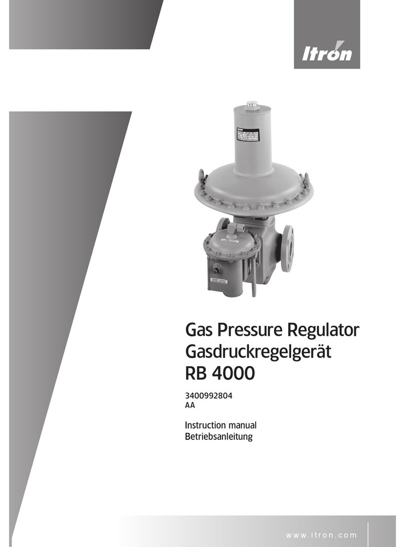
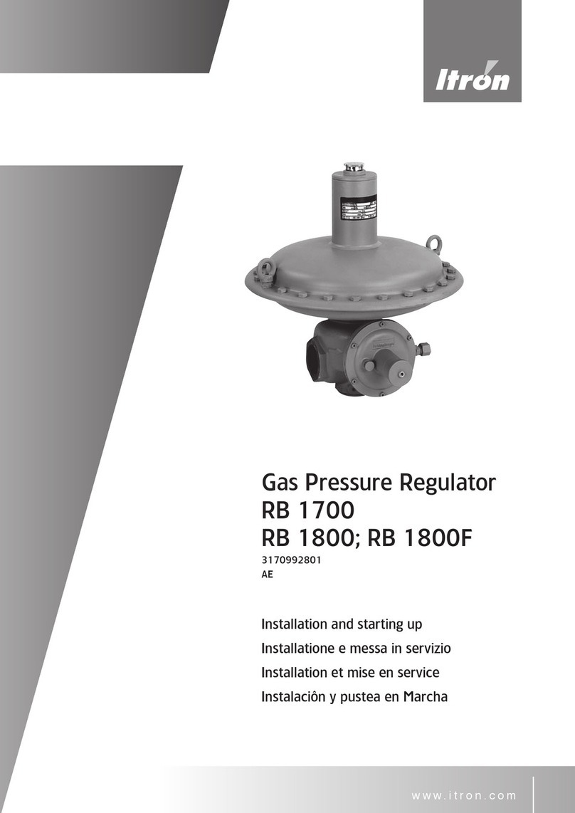
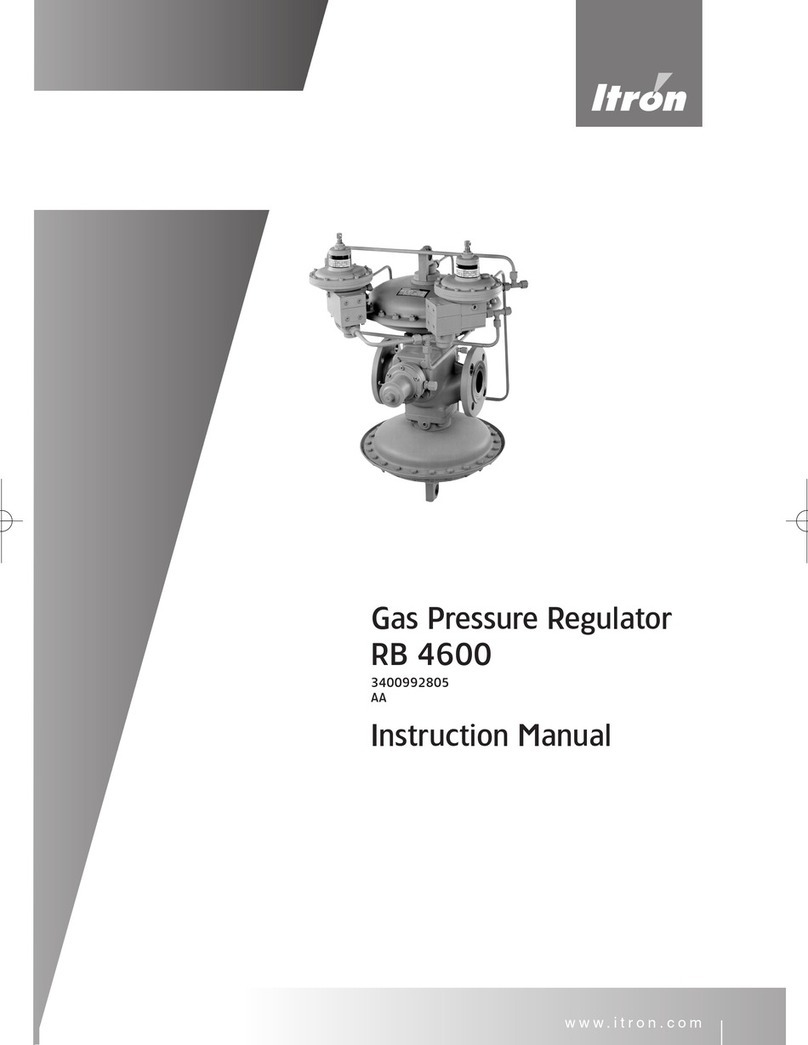
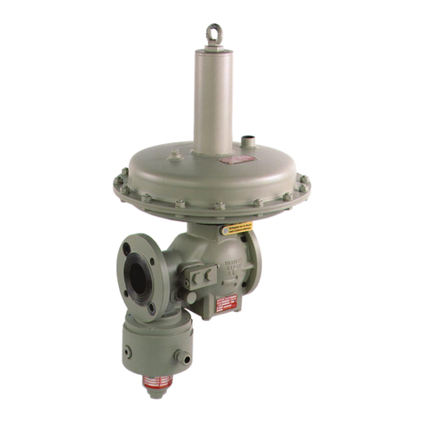
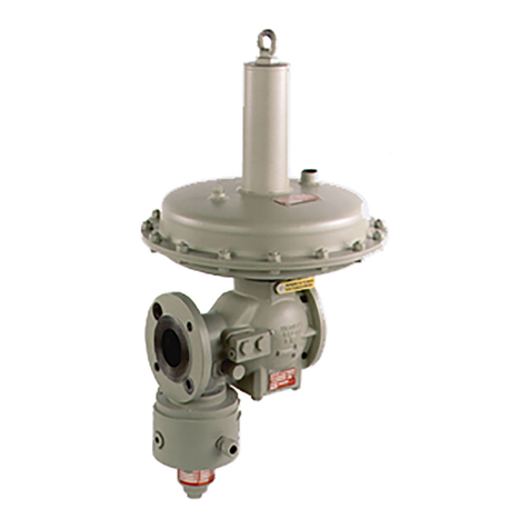
ITRON RB 4700 Series User manual

Gas Pressure Regulator
RB 4700
Устройство регулирования
давления газа
RB 4700 D
3400992806
AA
Instruction Manual
Inbetriebnahme Anleitung
Руководство по эксплуатации
www.itron.com

2

3
Page
Seite
Страница
GB EU Declaration of Conformity. . . . . . . . . . . . . . . . . . . . . . . . . . . . . . . . . . . . . . . . . . . . . . . . . . . . . . . . . . . . . . . . . . . . . . . . .4
Safety instructions . . . . . . . . . . . . . . . . . . . . . . . . . . . . . . . . . . . . . . . . . . . . . . . . . . . . . . . . . . . . . . . . . . . . . . . . . . . . . . .8 – 9
Description / technical data / Material / type-Selection. . . . . . . . . . . . . . . . . . . . . . . . . . . . . . . . . . . . . . . . . . . .18 – 19
Operating principle. . . . . . . . . . . . . . . . . . . . . . . . . . . . . . . . . . . . . . . . . . . . . . . . . . . . . . . . . . . . . . . . . . . . . . . . . . . .24 – 25
Pilot selection / Spring range of Pilot and SSV . . . . . . . . . . . . . . . . . . . . . . . . . . . . . . . . . . . . . . . . . . . . . . . . . .26 – 28
Dimension and Weight. . . . . . . . . . . . . . . . . . . . . . . . . . . . . . . . . . . . . . . . . . . . . . . . . . . . . . . . . . . . . . . . . . . . . . . . . . . . . 29
Schematic representation / Connection of pulse, - ventilation. . . . . . . . . . . . . . . . . . . . . . . . . . . . . . . . . . . . . . . . . 30
Installation / Start- up Instruction. . . . . . . . . . . . . . . . . . . . . . . . . . . . . . . . . . . . . . . . . . . . . . . . . . . . . . . . . . . . . . . . . . . . .31
SSV 8500 and 8600 description and resetting . . . . . . . . . . . . . . . . . . . . . . . . . . . . . . . . . . . . . . . . . . . . . . . . 34 – 37
DE EU-Konformitätserklärung . . . . . . . . . . . . . . . . . . . . . . . . . . . . . . . . . . . . . . . . . . . . . . . . . . . . . . . . . . . . . . . . . . . . . . . . . . .5
Sicherheitshinweise . . . . . . . . . . . . . . . . . . . . . . . . . . . . . . . . . . . . . . . . . . . . . . . . . . . . . . . . . . . . . . . . . . . . . . . . . . . .14 – 15
Beschreibung / Technische Daten /.Materialangaben / Typ-Auswahl. . . . . . . . . . . . . . . . . . . . . . . . . . . . . . 20 – 21
Funktionsprinzip . . . . . . . . . . . . . . . . . . . . . . . . . . . . . . . . . . . . . . . . . . . . . . . . . . . . . . . . . . . . . . . . . . . . . . . . . . . . . .24 – 25
Regler-Auswahl / Federbereiche Regler und SAV. . . . . . . . . . . . . . . . . . . . . . . . . . . . . . . . . . . . . . . . . . . . . . .26 – 28
Abmessungen und Gewichte. . . . . . . . . . . . . . . . . . . . . . . . . . . . . . . . . . . . . . . . . . . . . . . . . . . . . . . . . . . . . . . . . . . . . . . 29
Schematische Darstellung / Anschlüsse für Mess- & Atmungsleitung. . . . . . . . . . . . . . . . . . . . . . . . . . . . . . . . . 30
Einbauanleitung / Inbetriebnahme . . . . . . . . . . . . . . . . . . . . . . . . . . . . . . . . . . . . . . . . . . . . . . . . . . . . . . . . . . . . . . . . . . 32
SAV 8600 Beschreibung und Inbetriebnahme . . . . . . . . . . . . . . . . . . . . . . . . . . . . . . . . . . . . . . . . . . . . . . . . 30 – 31
FR Instructions de sécurité. . . . . . . . . . . . . . . . . . . . . . . . . . . . . . . . . . . . . . . . . . . . . . . . . . . . . . . . . . . . . . . . . . . . . . . . .12 – 13
Enconbrements et masses . . . . . . . . . . . . . . . . . . . . . . . . . . . . . . . . . . . . . . . . . . . . . . . . . . . . . . . . . . . . . . . . . . . . . . . . . 29
Présentation schématique et ligne d’impulsion, -respiration . . . . . . . . . . . . . . . . . . . . . . . . . . . . . . . . . . . . . . . . . . 30
I AInstruzione per la Sicurezza . . . . . . . . . . . . . . . . . . . . . . . . . . . . . . . . . . . . . . . . . . . . . . . . . . . . . . . . . . . . . . . . . . 10 - 11
RU Декларация соответствия ЕС. . . . . . . . . . . . . . . . . . . . . . . . . . . . . . . . . . . . . . . . . . . . . . . . . . 6
Указания по технике безопасности. . . . . . . . . . . . . . . . . . . . . . . . . . . . . . . . . . . . . . . . 16 – 17
Описание / Технические характеристики / Указания к материалам /
Выбор типа . . . . . . . . . . . . . . . . . . . . . . . . . . . . . . . . . . . . . . . . . . . . . . . . . . . . . . . . . . . . . 22 – 23
Принцип действия. . . . . . . . . . . . . . . . . . . . . . . . . . . . . . . . . . . . . . . . . . . . . . . . . . . . . . .24 – 25
Выбор регулятора / Диапазоны вых. давления регулятора и ПКО . . . . . . . . . . . . 26 – 28
Габаритные размеры и массы . . . . . . . . . . . . . . . . . . . . . . . . . . . . . . . . . . . . . . . . . . . . . . . . 29
Схематическое представление / Точки присоединения измерительной и
дыхательной линий. . . . . . . . . . . . . . . . . . . . . . . . . . . . . . . . . . . . . . . . . . . . . . . . . . . . . . . . . . 30
Руководство по монтажу / Пуско-наладка . . . . . . . . . . . . . . . . . . . . . . . . . . . . . . . . . . . . . 33
ПКО 8600 Описание и пуско-наладка. . . . . . . . . . . . . . . . . . . . . . . . . . . . . . . . . . . . . . 40 – 41
4
EU Declaration of Conformity
D2036209_AA_EU_Declaration_RB4700_4600.docx
Gas pressure regulators for natural gas and all non-corrosive gases
with or without safety shut-off valves for OPSO or OPSO and UPSO
Manufacturer: Itron GmbH, Hardeckstraße 2, D-75185 Karlsruhe
declares under his sole responsibility, that the regulator
RB4710 / 4720 / 4730 without SSV
RB4711/4712/4721/4722/4731/4732 with SSV8500 or SSV8600
RXI4710 / 4720 / 4730 without SSV
RXI4711/4712/4721/4722/4731/4732 with SSV8500 or SSV8600
RB4610 / 4620 / 4630 without SSV
RB4611/4612/4621/4622/4631/4632 with SSV8500 or SSV8600is in conformity
with the Pressure Equipment Directive 2014/68/EU
The regulator has been classified as pressure accessory in category II, by the
manufacturer. The used fluids are classified in group 1 according article 13.
Applied conformity assessment
procedures PED: Module D1
Applied standards and technical
specification: DIN EN 334:2005+A1:2009 and DIN EN 14382:2005+A1:2009+AC:2009
Other applied EC-Directives: 2014/30/EU, electromagnetic tolerance
only for optional electronic device
Engaged notified body:
Module D, Surveillance of the QS-System: TÜV SÜD Industrie Service GmbH, Westendstraße 199, D-80686 München
Examination/inspections/tests
during manufacturing: TÜV SÜD Industrie Service GmbH, Westendstraße 199, D-80686 München
Surveillance of the QS-System: DGR-0036-QS-955-14
Regulators and safety devices according to EN 334 and EN 14382 - if not equipped, with any electronic device – do not have a
potential ignition source and therefore are not in the scope of European directive 2014/34/EU.
Karlsruhe, July 19th, 2016
_____________________
P. Garcia
Head of Production

5
EU - Konformitätserklärung
D2036209_AA_EU_Declaration_RB4700_4600.docx
Druckregelgeräte für Erd-/Allgas
mit oder ohne Sicherheitsabsperrventil für oberen oder oberen und unteren Ansprechdruck
Der Hersteller: Itron GmbH, Hardeckstraße 2, D-75185 Karlsruhe
erklärt hiermit in alleiniger Verantwortung, dass die Gasdruckregelgeräte
RB4710 / 4720 / 4730 ohne SAV
RB4711/4712/4721/4722/4731/4732 mit integriertem SAV8500 oder SAV8600
RXI4710 / 4720 / 4730 ohne SAV
RXI4711/4712/4721/4722/4731/4732 mit integriertem SAV8500 oder SAV8600
RB4610 / 4620 / 4630 ohne SAV
RB4611/4612/4621/4622/4631/4632 mit integriertem SAV8500 oder SAV8600 mit
der Druckgeräterichtlinie 2014/68/EU übereinstimmen.
Die Geräte wurden vom Hersteller als druckhaltende Ausrüstungsteile in Kategorie
II eingestuft. Die Einstufung der Fluide erfolgte gemäß Artikel 13 in Stoffgruppe 1.
Angewandte
Konformitätsbewertungsverfahren PED: Modul D1
Angewandte Normen und technische
Spezifikationen: DIN EN 334:2005+A1:2009 und DIN EN 14382:2005+A1:2009+AC:2009
Weitere angewandte EU-Richtlinien: 2014/30/EU, elektromagnetische Verträglichkeit
nur für zusätzliche elektrische Einrichtungen
Eingeschaltete notifizierte Stellen:
Modul D, Überwachung QS-System: TÜV SÜD Industrie Service GmbH, Westendstraße 199, D-80686 München
Prüfung / Überwachung / Kontrollen
während der Fertigung: TÜV SÜD Industrie Service GmbH, Westendstraße 199, D-80686 München
Überwachung QS-System: DGR-0036-QS-955-14
Gas-Druckregelgeräte und Sicherheitsabsperrventile nach der Norm EN 334 und EN 14382 haben - sofern sie nicht mit
elektrischen Einrichtungen ausgerüstet sind – keine potenzielle Zündquelle und fallen daher nicht in den Anwendungsbereich
der europäischen Richtlinie 2014/34/EU.
Karlsruhe, 19.07.2016
_____________________
P. Garcia
Produktionsleiter

6

7

8
ENGLISH
IMPORTANT SAFETY INSTRUCTIONS:
· This "Instruction manual" has to be kept on the place, which can be easy reached.
· The regulator has to be used only for dry and clean gases. Never use with oxygen: risk of
explosion.
· The national norms and standards about installation, start-up and maintenance of the devices
and gas installations have to be strictly respected.
· The handling with the device has to be done carefully, specially by the installation works. The
pick up has to be made by using the stretcher eyes or belts.
· The device should be examined before the installation for possible transport damages and be
mounted only if it is in perfect state. Possible lacquer damage should be improved. The sealing
surfaces of the threaded connections or flanges must be damage-free and clean.
· For reading off the device and its serving are sufficiently space to designate.
· For the protection of the device is recommendable to install a filter.
· The device is to be installed in such a way that it is not impaired in its function by other installa-
tion components.
· The regulator has to be mounted in the pipe line without any tension.
· The mentioned below torque's values for screws must be respected by tighten of the flanged
connections:
· These torque's values are mentioned per screw and are valid for metal soft material gaskets
(specified as k0xKD=45bD und k1=2,2bD). Other gaskets can require another torque's values.
· The screws used for the flange connection must be according to the flange size and must be
adapted to the temperature range of the regulator. Please tighten the screws crosswise.
· After the installation works are completed, the tightness of the connections (threaded or
flanged) must be checked with appropriate means.
· The operating conditions indicated on the name plates must be respected; if necessary appro-
priate safety devices have to be designated.
· Repairs of the device are allowed to be made only by trained or qualified personal. Afterwards
a tightness test with 1.1 X PS must be performed. When changing pressure containing parts
their compliance with PED must be assured. After Guarantee only with repair by Actaris.
· The device has to be regularly examined for corrosion danger in the interior and external area
and be taken from use if noticeable corrosion is discovered.
DN25 DN40 DN50 DN80 DN100
PN16 35Nm
( M12 )
85Nm
( M16 )
85Nm
( M16 )
85Nm
( M16 )
85Nm
( M16 )
ANSI 150 55Nm
( M14 )
55Nm
( M14 )
85Nm
( M16 )
85Nm
( M16 )
85Nm
( M16 )
PN25 35Nm
( M12 )
85Nm
( M16 )
85Nm
( M16 )
85Nm
( M16 )
170Nm
( M20 )
ANSI 300 120 Nm
( M16, 8.8 )
– 120 Nm
( M16, 8.8 )
200Nm
( M20, 8.8 )
200 Nm
( M20, 8.8 )

9
· The cleaning of the devices has to be done without using any alcohol containing solvent or
cleaning agents.
· The device is not appropriate for floods and loads by earthquakes.
· The pressure has to be completely discharged before to take the device from the pipe line.
The rest of gas can withdraw, therefore the required ventilation has to be insured.
· The appropriate measures for noise reduction have to be seized depending on the installation
place and work conditions.
· The gas pressure reduction stations have to be fitted with safety devices, which must prevent
any exceed of the maximum allowable in the downstream network pressure.
· The gas pressure regulators have to be adjusted in such way, that the maximum allowable
pressure in the downstream network is not exceeded. The accuracy class has to be taken to
consideration as well.

10
ITALIANO
IMPORTANTI INSTRUZIONI PER LA SICUREZZA:
· Questo "Manuale d'istruzioni" dovrà essere conservato in un luogo dove possa essere
facilmente rintracciato.
· Il regolatore dovrà essere usato soltanto per gas secchi e puliti. Non usare mai con ossigeno:
si corre il rischio di esplosione.
· Dovranno essere rigorosamente osservate le norme e gli standard nazionali relativi a
istallazione, avvio e manutenzione del regolatore e delle installazioni di gas.
· L'apparecchiatura dovrà essere maneggiata con cura, in particolare durante i lavori di
installazione. Per prelevarla si dovranno impiegare fori di presa o cinture.
· Prima di procedere all'installazione si dovrà controllare il regolatore per eventuali danni subiti
durante il trasporto e si potrà montarlo soltanto se in perfette condizioni. Dovranno essere
eliminati possibili danni alla lacca. Le superfici di tenuta delle connessioni filettate o delle
flangie dovranno risultare esenti da danni e pulite.
· Dovrà essere lasciato spazio sufficiente per l'effettuazione della lettura dell'apparecchiatura e
per il servizio.
· Per la protezione del regolatore si raccomanda l'uso di un filtro o di un setaccio.
· Il regolatore dovrà esser installato in maniera tale che la sua funzione non possa essere
danneggiata da altri componenti dell'installazione. In particolare dovranno essere assicurate
efficacia ed operatività tramite linee di misurazione e sfiato. Si dovrà ricorrere a misure
adeguate per prevenire l'ingresso di corpi estranei, p.e. ricoprendolo con una griglia.
· Il regolatore si dovrà montare sulla conduttura senza tensione.
· Per il rispetto dei valori di coppia qui di seguito espressi si dovrà agire sulle connessioni
flangiate:
· Dopo il completamento dei lavori d'installazione dovrà essere verificata con mezzi appropriati
la tenuta delle connessioni (filettate o flangiate).
· La connessione flangiata dovrà essere tirata stretta dopo la regolazione.
· Dovranno essere osservate le condizioni operative indicate sulle targhette della casa
costruttrice; se necessario si dovrà ricorrere ad appropriati dispositivi di sicurezza.
· È previsto che le riparazioni dell'apparecchiatura siano effettuate soltanto da personale
qualificato o da specialisti del campo. La garanzia è valida solo se la riparazione è effettuata
da Actaris.
· L'apparecchiatura dovrà essere regolarmente esaminata per verificarne il pericolo di
corrosione interna ed esterna e rimossa ove se ne riscontri una corrosione evidente.
· Per la pulizia dell'apparecchiatura non si dovrà ricorrere a solventi contenenti alcol o detersivi.
· Non è previsto l'uso di questa apparecchiatura per il caso di allagamenti. Per il pericolo di
allagamenti dovranno essere prese misure adeguate. Per dettagli si prega di mettersi in
contatto con Actaris.
· L'apparecchiatura non è idonea in caso di terremoti. Per il pericolo di terremoti dovranno
· essere prese misure adeguate.
DN25 DN40 DN50 DN80 DN100
PN16 35Nm
( M12 )
85Nm
( M16 )
85Nm
( M16 )
85Nm
( M16 )
85Nm
( M16 )
ANSI 150 55Nm
( M14 )
55Nm
( M14 )
85Nm
( M16 )
85Nm
( M16 )
85Nm
( M16 )
PN25 35Nm
( M12 )
85Nm
( M16 )
85Nm
( M16 )
85Nm
( M16 )
170Nm
( M20 )
ANSI 300 120 Nm
( M16, 8.8 )
– 120 Nm
( M16, 8.8 )
200Nm
( M20, 8.8 )
200 Nm
( M20, 8.8 )

11
· Prima di rimuovere l'apparecchiatura dalla conduttura si dovrà scaricarne completamente la
pressione. Il gas residuo potrebbe ritirarsi, c'è bisogno pertanto della prevista ventilazione.
· Gli adeguati provvedimenti per la riduzione del rumore dovranno essere presi a secondo del
punto di installazione e delle condizioni di lavoro.
· Le stazioni di riduzione della pressione del gas dovranno essere dotate di dispositivi di
sicurezza per prevenire qualsiasi eccesso della pressione massima consentita a valle della rete.
· I regolatori di pressione del gas dovranno essere tarati in modo che nella rete a valle non
venga superata la pressione massima consentita. Si dovrà tenere conto anche dei livelli di
precisione relativi alla classe.

12
FRANCAIS
INSTRUCTIONS IMPORTANTES DE SECURITE:
· Ce "Manuel d'Instructions" doit rester en place à disposition et être accessible facilement.
· Les régulateurs doivent être utilisés uniquement pour des gaz propres et secs. En aucun cas
ils ne doivent être utilisés avec de l'oxygène : risque d'explosion.
· Les normes nationales et standard d'installation, de mise en service et de maintenance sur les
régulateurs et installations gaz doivent être rigoureusement respectées.
· Les manipulations sur l'appareil doivent être effectuées avec précautions, spécialement
lorsque l'installation est en fonctionnement. Dans tous les cas, l'appareil doit être manipulé en
utilisant les fixations et prises prévues à cette effet.
· Le régulateur doit être examiné avant sont installation afin de vérifier s'il n'a pas subi
dommages lors de son transport. Il sera monté uniquement s'il est en parfait état. Des
adaptations de surface peuvent être effectuées en cas de dommages sur le revêtement
(peinture). Les protections de surface sur les connections « brides ou taraudages » doivent
être libérés et nettoyés.
· Un espace suffisant doit être prévu pour permettre une lecture aisée des plaques
signalétiques et service.
· Pour la protection du régulateur, il est recommandé l'utilisation d'un système de filtration.
· Le régulateur doit être installé de façon à ce qu'il ne soit pas détérioré dans son
fonctionnement par d'autres composants de l'installation.
· L´appareil doit être monté sans tension sur la canalisation.
· Les valeurs de serrage mentionnées ci-dessous doivent être respectées afin de ne pas
dépasser les limites de résistance des brides de fixation :
· Les valeurs de serrage sont mentionnées pour chaque vis et doivent être applique avec le joint
d' étanchéité de matière douce (k0xKD=45bD und k1=2,2bD).
Les autres joints d' étanchéité peuvent exiger d'autres valeurs de serrage .
· Le type de vis doit être choisi en fonction de la bride et de la classe de température. Bloquer
les écrous en croix.
· Lorsque l'installation de l'appareil est terminée , s'assurer de l'étanchéité de la fixation
(taraudée ou brides) par des moyen appropriés.
· Les conditions de fonctionnement indiquées sur la plaque signalétique doivent être
impérativement respectées; si des dispositifs de sécurité appropriés sont nécessaires,
ceux-ci doivent être prévus.
· La réparation et la maintenance doivent être effectuée par des personnes qualifiées. Après
réparation un test d'étanchéité a 1,1 fois PS (pression maximum) doit être effectué. Lorsque
qu'une pièce sous pression est changée, il faut s'assurer de sa conformité a la PED. Seules les
interventions effectuées par Actaris pourront être garanties.
· Le dispositif doit être régulièrement examiné pour palier à d'éventuels risques de corrosion
interne ou externe de l'appareil. Celui-ci doit être mis hors fonctionnement si des marques de
corrosion sont repérées .
DN25 DN40 DN50 DN80 DN100
PN16 35Nm
( M12 )
85Nm
( M16 )
85Nm
( M16 )
85Nm
( M16 )
85Nm
( M16 )
ANSI 150 55Nm
( M14 )
55Nm
( M14 )
85Nm
( M16 )
85Nm
( M16 )
85Nm
( M16 )
PN25 35Nm
( M12 )
85Nm
( M16 )
85Nm
( M16 )
85Nm
( M16 )
170Nm
( M20 )
ANSI 300 120 Nm
( M16, 8.8 )
– 120 Nm
( M16, 8.8 )
200Nm
( M20, 8.8 )
200 Nm
( M20, 8.8 )

13
· Avant d'ôter l'appareil du réseau, s'assurer qu'il n'existe plus de pression à l'intérieur de
l'appareil et du réseau. Le reste de gaz présent peut se décharger lors du démontage.
S'assurer de la présence d'un dispositif de ventilation suffisant.
· Les mesures de réduction de bruit doivent être effectuées en fonction de l'installation et des
conditions de fonctionnement.
· Le nettoyage des appareils ne doit pas être effectué en utilisant des produits contenant de
l'alcool, des solvant ou des agents nettoyants non spécifiés.
· L'appareil n'est pas conçu pour une utilisation dans le cas d'inondations et pour résister à des
tremblements de terre.
· Les mesures de réduction de bruit doivent être effectuées en fonction de l'installation et des
conditions de fonctionnement.
· Les stations de détente du gaz doivent être équipées avec des dispositifs de sécurité pour
éviter un excès de la pression maximum possible dans le réseau.
· Les régulateurs de pression de gaz doivent être ajustés de façon à ce que la pression maximal
supporté par le réseau ne soit pas dépassée. La classe de précision doit aussi être prise en
considération.

14
DEUTSCH
WICHTIGE SICHERHEITSHINWEISE
· Diese Betriebsanleitung muss leicht zugänglich aufbewahrt werden.
· Nur für saubere und trockene Gase verwenden. Auf keinen Fall bei Sauerstoff anwenden: Explo-
sionsgefahr!
· Die nationalen Vorschriften für die Inbetriebnahme, den Betrieb und die Wartung von Gasgerä-
ten müssen eingehalten werden.
·
Geräte sollen an den vorgesehenen Trageösen oder mit Hilfe von Gurten angehoben werden.
·
Das Gerät sollte vor der Montage auf eventuelle Transportschäden untersucht werden und darf
nur in einwandfreiem Zustand montiert werden. Eventuelle Lackbeschädigungen sollten nach-
gebessert werden. Die Dichtflächen der Flansche müssen beschädigungsfrei und sauber sein.
·
Zum Warten und Bedienen ist ausreichend Bauraum vorzusehen.
·
Zum Schutz des Gerätes ist ein Filter empfehlenswert.
·
Das Gerät ist so zu installieren, dass es in seiner Funktion nicht durch andere Installationskom-
ponenten beeinträchtigt wird.
·
Das Gerät muss spannungsfrei in die Rohrleitung eingebaut werden.
·
Die angegebenen Anzugsdrehmomente der Schrauben dürfen nicht überschritten werden:
· Diese Anzugsmomente sind pro Schraube und gelten für Metallweichstoffdichtungen (mit den
Kenndaten k0xKD=45bD und k1=2,2bD.). Andere Dichtungen können andere Anzugsmomente
erfordern.
· Die Schrauben für die Flanschverbindung müssen der Flanschgröße entsprechen und für den
Temperaturbereich des Gerätes ausgelegt sein. Die Schrauben sind über kreuz anzuziehen.
· Nach dem Einbau muss die Dichtigkeit der Flanschverbindung überprüft werden.
· Die auf den Typenschildern angegebenen Betriebsbedingungen müssen eingehalten werden;
gegebenenfalls müssen entsprechende Sicherheitseinrichtungen vorgesehen werden.
· Reparaturen am Gerät dürfen nur von unterwiesenem Personal oder durch Fachkräfte erfolgen.
Danach ist ein Dichtheitstest mit 1,1xPS durchzuführen. Beim Austausch drucktragender Teile ist
darauf zu achten, dass diese der Druckgeräterichtlinie entsprechen. Gewährleistung nur bei
Reparatur durch Actaris.
· Bei Korrosionsgefahr im Innen- und Außenbereich muss das Gerät regelmäßig untersucht wer-
den und bei merklicher Korrosion aus dem Verkehr genommen werden.
· Zum Reinigen des Gerätes dürfen keine lösemittel- bzw. alkoholhaltigen Reinigungsmittel ver-
wendet werden.
· Das Gerät ist nicht für Erdbeben und Hochwasser ausgelegt.
· Vor dem Ausbau des Gerätes den Druck vollständig ablassen. Eine Restmenge Gas kann aus-
treten, deshalb ist für ausreichende Belüftung zu sorgen.
DN25 DN40 DN50 DN80 DN100
PN16 35Nm
( M12 )
85Nm
( M16 )
85Nm
( M16 )
85Nm
( M16 )
85Nm
( M16 )
ANSI 150 55Nm
( M14 )
55Nm
( M14 )
85Nm
( M16 )
85Nm
( M16 )
85Nm
( M16 )
PN25 35Nm
( M12 )
85Nm
( M16 )
85Nm
( M16 )
85Nm
( M16 )
170Nm
( M20 )
ANSI 300 120 Nm
( M16, 8.8 )
– 120 Nm
( M16, 8.8 )
200Nm
( M20, 8.8 )
200 Nm
( M20, 8.8 )

15
· Abhängig vom Aufstellungsort des Gerätes sind gegebenenfalls Schallschutzmaßnahmen zu
treffen.
· Gas-Druckregelanlagen müssen mit Sicherheitseinrichtungen ausgerüstet sein, die ein unzuläs-
siges Überschreiten des höchstzulässigen Betriebsdruckes in den nachgeschalteten Anlagentei-
len und Leitungen sicher verhindert.
· Gas-Druckregelgeräte müssen so eingestellt werden, dass der höchstzulässige Betriebsdruck
des nachgeschalteten Versorgungssystems auch unter Berücksichtigung der Regelgüte nicht
überschritten wird.

16
РУССКИЙ
ВАЖНЫЕ УКАЗАНИЯ ПО ТЕХНИКЕ БЕЗОПАСНОСТИ
· Храните данное руководство по эксплуатации в легкодоступном месте.
· Используйте устройство только для чистых и сухих газов. Ни в коем случае не исполь-
зовать с кислородом: Взрывоопасно!
· Отечественные правила в области ввода в эксплуатацию, работы, и технического об-
служивания газового оборудования должны соблюдаться в обязательном порядке.
· Поднимайте устройства только по предусмотренным для этого подъемным рымам
или с помощью ремней.
· Перед монтажом проверить устройство на наличие возможных транспортных по-
вреждений; монтаж УРДГ допускается только в безупречном состоянии. Поправьте
возможные неисправности лакового покрытия. Уплотняющие поверхности фланцев
должны быть без каких-либо повреждений и загрязнений.
· Предусмотрите достаточное свободное пространство для техобслуживания и опера-
ции оборудования.
· Для защиты устройства рекомендуем использовать фильтр.
· Проведите установку устройства таким образом, чтобы другие компоненты инстал-
ляции не препятствовали его функционированию.
· Установите устройство в трубопровод без напряжений.
· Указанные моменты затяжки винтов превышать нельзя:
· Указанные моменты затяжки относятся к отдельному винту и к металлическим мяг-
ким уплотнениям (с параметрами k0xKD=45bDи k1=2,2bD.). Другие уплотнения могут
требовать других моментов затяжки.
· Болты для фланцевого соединения должны соответствовать размеру фланца и долж-
ны быть подобраны с учетом температурного диапазона устройства. Затянуть болты
крест-накрест.
· После монтажа следует проверить герметичность фланцевого соединения.
· Указанные на типовых табличках условия эксплуатации соблюдать в обязательном
порядке; по мере необходимости предусмотреть соответствующие устройства тех-
ники безопасности.
· Проведение ремонта устройства разрешается только обученному персоналу или
специалистам. Затем провести испытание на герметичность с 1,1xPзад. В случае
замены работающих под давлением деталей следить за тем, чтобы они соответство-
вали директиве по устройствам регулирования давления. Гарантия предоставляется
только в случае ремонта фирмой Actaris.
· В случае опасности коррозии внутренних и внешних поверхностей устройство тре-
бует периодической проверки, а в случае заметной коррозии, устройство надо вы-
вести из эксплуатации.
· Для очистки устройства средства, содержащие растворители или спирт, использо-
вать нельзя.
Ду25 Ду40 Ду50 Ду80 Ду100
Pу16 35Нм
( M12)
85Нм
( M16 )
85Нм
( M16 )
85Нм
( M16 )
85Нм
( M16 )
ANSI 150 55Нм
( M14 )
55Нм
( M14 )
85Нм
( M16 )
85Нм
( M16 )
85Нм
( M16 )
Ру 25 35Нм
( M12)
85Нм
( M16 )
85Нм
( M16 )
85Нм
( M16 )
170Нм
( M20 )
ANSI 300 120 Нм
( M16, 8.8 )
– 120 Нм
( M16, 8.8 )
200Нм
( M20, 8.8 )
200 Нм
( M20, 8.8 )

17
· Устройство не предназначено ни для землетрясения, ни для наводнения.
· Перед демонтажем устройства полностью сбросить давление. Возможен выход
остаточного количества газа, поэтому обеспечьте достаточную аэрацию.
· В зависимости от места установки устройства, принятие мер по шумозащите может
быть необходимым.
· На установках регулирования давления газа должны быть предусмотрены предохра-
нительные устройства техники безопасности, которые надежно препятствуют недо-
пустимому превышению максимально допустимого рабочего давления в последова-
тельно присоединенных частях и трубопроводах установки.
· Устройства регулирования давления газа должны быть налажены так, чтобы макси-
мально допустимое рабочее давление послевключенной системы снабжения не пре-
вышалось, также не с учетом качества регулирования.

18
Description
The RB 4700 and RB 4700 D is a pilot-operated regulator with an integrated optional safety shut-off
device. The balanced compensation system ensures constant outlet pressure when the upstream pres-
sure varies. This regulator has a very high operating performance.
Applications
It is designed for use in industrial and distribution applications: such as gas supply networks, district sta-
tions, heating plants and industries.
It can also be used for all installations with continuous consumption and rapid variations of flow-rate.
The accurate pressure control and fast response of the regulator are ensured by the perfect operating
performance of the pilot.
Technical features (CE-conform, DVGW-approval* see leaflet)
· Inlet pressure Pu: (Pd + 0.5 bar) - 19.2 bar / 25 bar
· Outlet pressure Pd: 5 mbar - 13 bar
· Accuracy class 5 - 20 mbar: AC 20 / SG 50
20 - 50 mbar: AC 10 / SG 30
50 - 200 mbar: AC 5 / SG 10
0.2 - 13 bar: AC 2.5 / SG 10
AG 30 - AG 1
· Temperature range -20°C to +60°C
· Ambient temperature -30°C to +60°C
· Acceptable gases Natural gas, town gas, propane, butane,
air, nitrogen or any non-corrosive gas
· Installation Horizontal or vertical
· Safety devices Optional built-in, safety shut-off valve:
Over-pressure shut-off (OPSO)
and low-pressure shut-off (LPSO)
· Available Valve position indicator
Silent version / noise reduction
Connections
· Sizes DN 25, DN 40, DN 50, DN80, DN100
· Body lengths According to EN 334
· Flanges Steel: PN16, PN20 (ANSI150), PN25, ANSI 300*
Cast iron: PN16, PN20 (ANSI150)
* with exception of DN 40

19
Materials
Body Spheroid graphite cast-iron EN-GJS-400-15 DIN 1693
Cast Steel G 20Mn5N
Pilot Blocks: steel UNI 5105
Cover: aluminum UNI 6362
Head Pressed steel / UNI EN10025
Internal parts Stainless steel and brass
Seals Nitrile rubber
Diaphragm Polyester fabric
* DVGW approval for Pemax = 16 bar (with modified diaphragm housing).
Selection of the regulator version
To specify the version of the RB 4700 series to be ordered, the options and
relevant codes should be selected from the table below.
R X X 4 7 X X - D DN X Variants
B Balanced - High accuracy version
E External impulse
1 Low pressure (TF 511): 5 - 280 mbar
2 Medium pressure (TF 512): 0.1 - 1 bar
3 High pressure (TF 513): 0.25 - 13 bar
0 Without safety devices
1 Over-pressure shut-off valve
2 Over- and low-pressure shut-off valve
- D DVGW approval
25 Orifice (Ø 30 mm)
40 Orifice (Ø 38 mm)
50 Orifice (Ø 48 mm)
80 Orifice (Ø 78 mm)
10 0 Orifice (Ø 98 mm)
S Silent version
Example: Model RBE 4711 DN25 S is a regulator with a TF 511 pilot, an over-pressure shut-off and
silencer.
Selection of the safety shut-off options
SSV 8600 with: DN 25 / 40 / 50 / 80 / 100
SSV 8500 with: DN 25 /40 / 50 / 80 (Please contact for Pe>=6 bar by DN50-DN80)
Safety device features
Manual bottom control for voluntary intervention
Manual reset
Built-in by-pass system

20
Beschreibung
Das Gasdruckregelgerät RB 4700 und RB 4700-D ist ein indirekt wirkendes Regelgerät mit optional
integrierbarem Sicherheitsabsperrventil (SAV).
Durch einen Vordruckausgleich werden variable Eingangsdrücke kompensiert. Das Regelsystem mit
Vorstufe und Regler erlaubt beste Regelgenauigkeit.
Anwendungen
Diese Geräte wurden für Anwendungen in Industrie und Gasversorgungsnetzen entwickelt.
Technische Daten (CE konform, DVGW Zulassung* siehe deutsches Prospekt)
· Eingangsdruck Pu: (Pd + 0.5 bar) bis zu 19.2 bar / 25 bar
· Ausgangsdruck Pd: 5 mbar - 13 bar
· Regelgruppe 5 - 20 mbar: AC 20 / SG 50
20 - 50 mbar: AC 10 / SG 30
50 - 200 mbar: AC 5 / SG 10
0.2 - 13 bar: AC 2.5 / SG 10
· SAV Ansprechgruppe AG 30 - AG 1
· Temperaturbereich -20°C bis +60°C
· Umgebungstemperaturbereich -30°C bis +60°C
· geeignet für alle Gase nach DVGW Arbeitsblatt G260
· Einbau horizontal und vertikal möglich
· optional einbaubares SAV:
für obere - und untere Abschaltung und Membranbruchsicherung (SAV 8600)
· optional
SAV Stellungsanzeiger
Schalldämpfer zur Geräuschreduzierung
Anschlussgrößen
· Nennweiten DN 25, DN 40, DN 50, DN80, DN100
· Baulängen nach den Empfehlungen aus EN 334
· Flansche Stahl: PN16, PN20 (ANSI150), PN25, ANSI 300*
· Flansche Guss: PN16, PN20 (ANSI150)
· nach ISO 7005
* mit Ausnahme von DN 40
This manual suits for next models
7
Table of contents
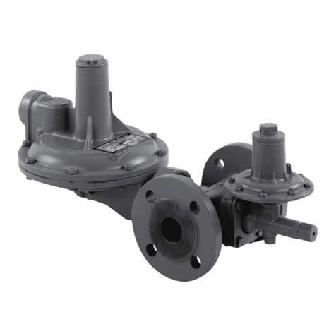
Other ITRON Controllers manuals

ITRON
ITRON RB 3200 User manual

ITRON
ITRON MLOG User manual

ITRON
ITRON RB 4000 Instructions and recipes

ITRON
ITRON RB1700 How to use

ITRON
ITRON RB 4000 User manual

ITRON
ITRON 133 User manual

ITRON
ITRON RB 4600 User manual

ITRON
ITRON RB 4000 User manual

ITRON
ITRON RR 16 User manual

ITRON
ITRON RR 16 User manual