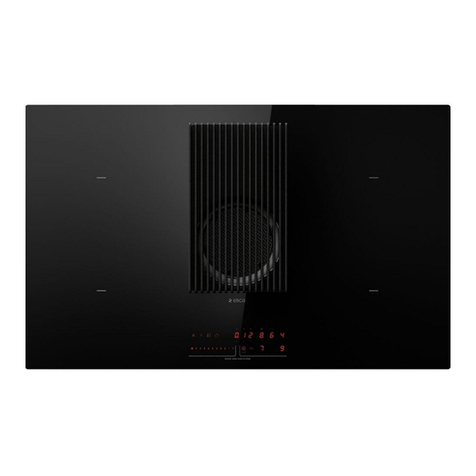
ELICA FLAME GR/F/88 User guide

,7 8VRH0DQXWHQ]LRQH
(1 8VHDQG0DLQWHQDQFH
'( %HWULHEXQG:DUWXQJ
)5 (PSORLHWHQWUHWLHQ
1/ *HEUXLNHQ2QGHUKRXG
(6 8VR\0DQWHQLPLHQWR
37 8WLOL]DomRH0DQXWHQomR
(/ ȋȡȒıȘțĮȚȈȣȞIJȒȡȘıȘ
69 $QYlQGQLQJRFKXQGHUKnOO
), .l\WW|MDKXROWR
12 %UXNRJYHGOLNHKROG
'$ %UXJRJYHGOLJHKROGHOVH
3/ 8Ī\WNRZDQLHL.RQVHUZDFMD
&6 3RXåLWtD~GUåED
6. 3RXåLWLHD~GUåED
+8 +DV]QiODWpVNDUEDQWDUWiV
%* ɍɩɨɬɪɟɛɚɢɉɨɞɞɪɴɠɤɚ
52 8WLOL]DUH܈LÌQWUH܊LQHUH
58 ɗɤɫɩɥɭɚɬɚɰɢɹɢɬɟɯɨɛɫɥɭɠɢɜɚɧɢɟ
8. ȿɤɫɩɥɭɚɬɚɰɿɹɿɬɟɯɨɛɫɥɭɝɨɜɭɜɚɧɧɹ
..ɉɚɣɞɚɥɚɧɭжəɧɟɬɟɯɧɢɤɚɥɵԕԕɵɡɦɟɬɤԧɪɫɟɬɭ
(7 .DVXWXVMDKRROGXV
/7 1DXGRMLPDVLUSULHåLnjUD
/9 /LHWRãDQDXQDSNRSH
65 8SRWUHEDLRGUåDYDQMH
6/ 8SRUDEDLQ9]GUåHYDQMH
+5 8SRUDEDLRGUåDYDQMH
75 .XOODQÕPYH%DNÕP
$5 ΓϥϱιϝϭϡΩΥ

'RZQORDGD
45&RGH5HDGHUDSS
6FDQ45FRGH 'RZQORDG
\RXU0DQXDO

PLQFP
PLQFP
PLQFP
PLQFP


IT
1. ISTRUZIONI D'USO
1.1 Recipienti per la cottura
1.1.1 Recipienti preesistenti
N.B.= si consiglia di usare pentole di diametro adatto ai
bruciatori evitando che la fiamma al massimo fuoriesca dal
fondo delle stesse
Per ottenere migliori risultati si consiglia di:
- Utilizzare tegami e pentole con diametro del fondo adatto alle
dimensioni dei bruciatori.
Per vedere il diametro della pentola da utilizzare su ogni
singolo bruciatore, consultare la parte illustrata di questo
manuale.
- Utilizzare soltanto pentole e tegami con fondi piatti.
- Dove possibile, tenere il coperchio sulle pentole durante la
cottura
-Cuocere verdure, patate, ecc. con una piccola quantità d’acqua
per ridurre il tempo di cottura.
- Utilizzare la pentola a pressione, riduce ulteriormente il
consumo di energia e il tempo di cottura
- Posizionare la pentola nel centro della zona di cottura
disegnata sul piano.
- Per un minor consumo di energia si consiglia di regolare i
bruciatori al livello adeguato alla cottura in corso. Per la
massima efficacia nell’aspirazione dei vapori sistemare un
mestolo tra coperchio e pentola, in particolare con pentole alte.
2. UTILIZZO DELL'ASPIRATORE
Il sistema di aspirazione può essere utilizzato in versione
aspirante ad evacuazione esterna o filtrante a ricircolo interno.
Consultare i siti www.elica.com e www.shop.elica.com per
verificare la gamma completa dei kit disponibili, per poter
eseguire le diverse installazioni, sia in filtrante sia in aspirante.
2.1 Versione aspirante
I vapori vengono evacuati verso l’esterno tramite una serie di
tubazioni (da acquistare saparatamente) fissate alla flangia di
raccordo già in dotazione.
Il diametro del tubo di scarico deve essere equivalente al
diametro dell'anello di connessione:
- in caso di uscita rettangolare 222 x 89 mm
- in caso di uscita tonda Ø 150 mm (*)
Per maggiori informazioni vedere la pagina relativa agli
accessori della versione aspirante nella parte illustrata di questo
manuale. Collegare il prodotto a tubi e fori di scarico a parete
con diametro equivalente all'uscita d'aria (flangia di raccordo).
L'utilizzo di tubi e fori di scarico a parete con diametro inferiore
determinerà una diminuzione delle prestazioni di aspirazione ed
un drastico aumento della rumorosità.
Si declina perciò ogni responsabilità in merito.
Usare un condotto il più corto possibile.
Usare un condotto con minor numero di curve possibile
(angolo massimo della curva: 90°).
Evitare cambiamenti drastici di sezione del condotto.
2.2 Versione Filtrante
L'aria aspirata verrà filtrata tramite appositi filtri grassi e filtri
odori prima di essere riconvogliata nella stanza.
Il prodotto viene fornito con tutto il necessario per
un'installazione standard con l'uscita dell'aria nella parte frontale
dello zoccolo del mobile.
Sono già inclusi nella confezione quattro batterie di filtri che
trattengono gli odori grazie ai carboni attivi.
I carboni attivi sono integrati in una matrice tessuto non tessuto
che li rende facilmente e completamente accessibili dalle
impurità, creando così un'elevata superficie di assorbimento.
Per maggiori informazioni vedere la pagina relativa agli
accessori della versione filtrante (nella parte illustrata di questo
manuale).
Consultare i siti www.elica.com e www.shop.elica.com per
verificare la gamma completa dei kit disponibili, per poter
eseguire le diverse installazioni, sia in filtrante sia in
aspirante.

3. FUNZIONAMENTO
3.1 Pannello di controllo
1- Bruciatore semirapido
2- Bruciatore Dual
3- Bruciatore rapido
4- Bruciatore semirapido
5- Zona di aspirazione / Griglia amovibile
6- Griglie amovibili
7- Manopole di comnado :
a . Accensione/spegnimento bruciatore a gas
b . Accensione/spegnimento bruciatore a gas Dual
c . Accensione/spegnimento aspiratore

4 Utilizzo del piano di cottura
UTILIZZO DEL PIANO COTTURA
L’accensione dei bruciatori avviene premendo sulla manopola
corrispondente (1) e ruotando la manopola stessa in senso
antiorario, sino a farne coincidere l’indice con la posizione di
massimo
La scarica elettrica fra candelina e bruciatore dà luogo
all’accensione del bruciatore interessato. Ad accensione
avvenuta rilasciare immediatamente la manopola regolando la
fiamma secondo necessità.
L’accensione del bruciatore avviene tenendo premuta a fondo la
manopola nella posizione di massimo per circa 3/5 secondi. Nel
rilasciare la manopola assicurarsi che il bruciatore rimanga
acceso.
NB = in caso di mancanza di energia elettrica l'accensione può
essere eseguita agendo sulla manopola allo stesso modo e
avvicinando una fiammella ai fori della parte superiore del
bruciatore.
L'accensione del bruciatore Dual avviene con la stessa
modalità, premendo e ruotando la manopola corrispondente (2).
Per questo tipo di buciatore è possibile accendere la fiamma
centrale (F1) ruotando e premendo la manopola in senso orario,
oppure accendere tutto il bruciatore (F1+F2) ruotando e
premendo la manopola in senso antiorario.
UTILIZZO DELL’ASPIRATORE
NB = la manopola dell’aspiratore è dotata di un dischetto rotativo
retroilluminato; in base alla funzione da eseguire la manopola
può essere ruotata o premuta.
•Per selezionare le velocità di aspirazione disponibili:
Girare la manopola (3) in senso orario per accendere ed
aumentare la velocità di aspirazione e in senso antiorario per
diminuirla, e spegnere la cappa.
La corona (L) si illumina ad indicare la velocità di aspirazione
selezionata :
•L1 acceso
velocità 1
•L1+L2 accesi
velocità 2
.•L1+L2+L3 accesi
velocità 3
•L1+L2+L3+L4-lampeggia lentamente
velocità 4 (Boost 1) : durata 30 minuti, dopodichè la cappa si
posiziona automaticamente alla velocità 3
•L1+L2+L3+L4-lampeggia velocemente
velocità 5 (Boost 2) : durata 7 minuti, dopodichè la cappa si
posiziona automaticamente alla velocità 3
•L spenta:
Motore di aspirazione spento
•Timer
L’aspiratore è dotato di una funzione timer, di spegimento
automatico temporizzato.
NB = il timer non è previsto per le velocità Boost 1 e Boost 2,
che sono già temporizzate
Per attivare il Timer premere la manopola (3-T) per 2 secondi;
- se si sta utilizzando la velocità 1 : la cappa si spegnerà
automaticamente dopo 15 minuti (L1 lampeggia)
- se si sta utilizzando la velocità 2 : la cappa si spegnerà
automaticamente dopo 10 minuti (L1 rimane fisso –L2
lampeggia)
- se si sta utilizzando la velocità 3 : la cappa si spegnerà
automaticamente dopo 5 minuti (L1+L2 rimangono fissi - L3
lampeggia)
•Dispositivo di controllo saturazione filtri
La cappa è fornita di un dispositivo che segnala quando si deve
eseguire la manutenzione dei filtri
Per attivare il dispositivo di controllo saturazione filtri, procedere
come segue:
1-Spegnere la cappa..
2-Premere la manopola (3-T), per 5 secondi;
la corona (L) si accende completamente, lampeggiando, per
indicare che siamo entrati nel menù di settaggio filtri
NB = Il dispositivo di controllo saturazione del filtro antigrasso è
solitamente già attivato;
il dispositivo di controllo del filtro ai carboni attivi è solitamente
disattivato
3a -Filtro antigrasso
Girare la manopola (3) in senso orario L2+L3 sono accesi a
luce fissa
Premere la manopola: L2 +L3 iniziano a lampeggiare, il
dispositivo di controllo del filtro antigrassi è disattivato
Premere la manopola: L2 +L3 passano a luce fissa, il dispositivo
di controllo del filtro antigrassi è attivato
3b -Filtro ai carboni attivi
Girare la manopola (3) in senso antiorario L1+L4 sono accesi a
luce lampeggiante

Premere la manopola: L1 +L4 passano a luce fissa, il dispositivo
di controllo del filtro ai carboni è attivato
Premere la manopola: L1 +L4 iniziano a lampeggiare, il
dispositivo di controllo del filtro ai carboni è disattivato
4-Premere di nuovo la manopola (3-T) per 5 secondi; la corona
(L) lampeggia, poi si spegne, ad indicare che siamo usciti dal
menu di settaggio filtri
NB = dopo 1 minuto si esce comunque in automatico dal Menù
Segnalazione saturazione del filtro antigrasso
L2 + L3 lampeggiano quando si deve eseguire la manutenzione
del filtro antigrasso
Segnalazione saturazione del filtro ai carboni attivi
L1 + L4 lampeggiano quando si deve eseguire la manutenzione
del filtro ai carboni attivi
Reset della segnalazione di saturazione filtri
Dopo la manutenzione dei filtri premere la manopola (3-T) per 4
secondi: i led Lsi spegneranno, a conferma dell'avvenuto reset.
Nota: in caso di segnalazione contemporanea (saturazione filtro
antigrassi e filtro ai carboni attivi), è necessario ripetere
l’operazione di reset per due volte.
Tabella di potenza
ALIMENTAZIONE
BRUCIATORI
MARCATURA
INIETTORE
PORTATA
Kw
CONSUMO
PRESSIONE DEL GAS
TIPO
PRESSIONE mbar
NORM.
min.
nom.
max
Gas
G20 20mbar
17
20
25
DUAL ESTER - B
89
2,7
334 l/h
DUAL CENT -A
68
0,8
RAPIDO
125
3
286 l/h
SEMIRAPIDO
97
1,75
167 l/h
Gas
G30 29mbar
20
28-30
35
DUAL ESTER - B
63
2,7
255 g/h
DUAL CENT -A
46
0,8
RAPIDO
80
2,5
182 g/h
SEMIRAPIDO
66
1,75
127 g/h
Gas
G25.3 25mbar
20
25
30
DUAL ESTER - B
92
2,7
382 l/h
DUAL CENT -A
71
0,8
RAPIDO
130
3
327l/h
SEMIRAPIDO
100
1,75
191 l/h
Gas
G30 50mbar
42,5
50
57,5
DUAL ESTER - B
54
2,7
255 g/h
DUAL CENT -A
40
0,8
RAPIDO
78
3
218 g/h
SEMIRAPIDO
60
1,75
127 g/h
DUAL ESTERN - B
DUAL CENT - A
Nota: le configurazioni valide sono quelle relative agli ugelli presenti a corredo (che variano a seconda del prodotto).

4. MANUTENZIONE
Attenzione! Prima di qualsiasi operazione di pulizia o
manutenzione, assicurarsi che le zone di cottura siano
spente e fredde.
4.1 Manutenzione del piano di cottura
4.1.1 Pulizia
Il piano cottura va pulito dopo ogni utilizzo.
Importante:
Non utilizzare spugne abrasive, pagliette. Il loro impiego, col
tempo, potrebbe rovinare il vetro.
Non utilizzare detergenti chimici irritanti, quali spray per forno o
smacchiatori.
Dopo ogni uso, lasciare raffreddare il piano e pulirlo per
rimuovere incrostazioni e macchie dovute a residui di cibo.
Zucchero o alimenti ad alto contenuto zuccherino danneggiano il
piano cottura e vanno rimossi immediatamente.
Sale, zucchero e sabbia potrebbero graffiare la superficie del
vetro.
Usare un panno morbido, carta assorbente da cucina o prodotti
specifici per la pulizia del piano (attenersi alle indicazioni del
Fabbricante).
NON UTILIZZARE PULITRICI A GETTO DI VAPORE!!!
Per una maggiore durata dell’apparecchiatura è indispensabile
eseguire periodicamente un’accurata pulizia generale tenendo
presente quanto segue:
• le parti in vetro, acciaio e/o smaltate devono essere pulite con
prodotti idonei (reperibili in commercio) non abrasivi o corrosivi.
Evitare prodotti a base di cloro (varechina, ecc.)
• evitare di lasciare sul piano lavoro sostanze acide o alcaline
(aceto, sale, succo di limone, ecc.)•
gli spartifiamma ed i coperchietti (parti mobili del bruciatore)
vanno frequentemente lavati con acqua bollente e detersivo
avendo cura di togliere ogni eventuale incrostazione, asciugati
accuratamente, controllare che nessuno dei fori dello
spartifiamma risulti otturato anche parzialmente.
Dopo aver effettuato la pulizia riposizionare le griglie e i
bruciatori in modo corretto.
a. DISPOSITIVO DI SICUREZZA
b. Candela di accensione dei BRUCIATORI GAS
N.B.- L’eventuale lubrificazione dei rubinetti deve essere
eseguita da personale qualificato al quale è bene rivolgersi
in caso di anomalie di funzionamento.Controllare
periodicamente lo stato di conservazione del tubo flessibile
di alimentazione gas. In caso di perdite richiedere
l’immediato intervento del personale qualificato per la
sostituzione.
Importante:
In caso di fuoriuscite accidentali e abbondanti di liquidi dalle
pentole è possibile intervenire attraverso la valvola di scarico,
posta sulla parte inferiore del prodotto, in modo da poter
eliminare ogni residuo e poter eseguire una pulizia con la
massima sicurezza igienica.
Fig. 1
Per una pulizia più completa ed approfondita si può rimuovere
completamente la vasca inferiore
Fig. 2
4.2 Manutenzione del sistema aspirante
4.2.1 Pulizia
Per la pulizia usare ESCLUSIVAMENTE un panno inumidito con
detersivi liquidi neutri. NON UTILIZZARE UTENSILI O
STRUMENTI PER LA PULIZIA! Evitare l’uso di prodotti
contenenti abrasivi. NON UTILIZZARE ALCOOL!
4.2.2 Filtro grassi
Fig. 3
Filtro antigrasso
Trattiene le particelle di grasso derivanti dalla cottura.
Deve essere pulito una volta al mese (o quando il sistema di
indicazione di saturazione dei filtri indica questa necessità), con
detergenti non aggressivi, manualmente oppure in lavastoviglie
a basse temperature ed a ciclo breve.
Con il lavaggio in lavastoviglie il filtro antigrasso metallico può
scolorirsi ma le sue caratteristiche di filtraggio non cambiano
assolutamente.
4.2.3 Filtro odori
Filtro Ai Carboni Attivi - Plissettato
(Solo per Versione Filtrante)
I filtri trattengono gli odori grazie ai carboni attivi. I carboni attivi
sono integrati in una matrice tessuto non tessuto che li rende
facilmente e completamente accessibili dalle impurità, creando
così un'elevata superficie di assorbimento. La saturazione dei
filtri a carboni attivi si verifica dopo un uso più o meno
prolungato a seconda del tipo di cucina e della regolarità della
pulizia del filtro grassi. Questi filtri odori non possono essere
rigenerati e vanno sostituiti all’attivarsi della spia di
segnalazione.
Fig. 4

EN
1. INSTRUCTIONS FOR USE
1.1 Cooking containers
1.1.1 Pre-existing containers
2.2 Energy saving
NB = use pans with a suitable diameter for the burners and
make sure the highest flame does not protrude from under
them
Recommendations for best results:
- Use pots and pans with a base diameter suitable for the size of
the burners.
To see the diameter of the pan to use on each individual
burner, consult the relevant section in this manual.
- Use only pots and pans with flat bottoms.
- Where possible, keep the lid on pots during cooking
- Cook vegetables, potatoes, etc. with a minimal amount of water
to reduce cooking time.
- Use a pressure cooker, as it further reduces the energy
consumption and cooking time
- Place the pot in the centre of the cooking zone drawn on the
hob.
- To reduce power consumption, the burners should be adjusted
to suit the cooking under way. For best extraction of vapours,
place a ladle between the lid and the pot, in particular in the
case of tall pots.
2. USING THE EXTRACTOR
The extraction system can be used as a suction version with an
external exhaust or a filter version with internal recirculation.
Consult the website www.elica.com and www.shop.elica.com to
view the full range of available kits for carrying out the various
installations in filter and suction versions.
2.1 Suction Version
The fumes are evacuated towards the outside through a series
of pipes (bought separately) fastened to the supplied connecting
flange.
The diameter of the exhaust pipe must be equivalent to the
diameter of the connecting ring:
- for rectangular outlets 222 x 89 mm
- for circular outlets Ø 150 mm (*)
For more information, see the page relative to the extraction
version in the illustrated part of this manual. Connect the product
to wall-mounted exhaust pipes and holes with a diameter
equivalent to the air outlet (connecting flange).
Using wall-mounted exhaust pipes and holes with a smaller
diameter may reduce the efficiency of extraction and drastically
increase noise levels.
All responsibility in this regard is therefore denied.
Keep duct as short as possible.
Use ducting with the least possible number of curves
(maximum angle: 90°).
Avoid drastic changes in the ducting diameter.
2.2 Filter version
The extracted air will be filtered in special grease filters and
odour filters before being sent back into the room.
The product is supplied with all parts necessary for standard
installation, with the air outlet positioned in the front part of the
cabinet plinth.
The product is equipped with four filter packs that trap odours
thanks to the activated carbons.
The activated carbons are integrated into a non-woven fabric
matrix, making them easily and completely accessible to
impurities, thus creating a high absorption surface.
For more information, see the page relative to the filtration
version (in the illustrated part of this manual).
Visit the websites www.elica.com and www.shop.elica.com
to check the complete range of available kits for different
types of filtration and extraction installations.

3. OPERATION
3.1 Control panel
1- Semi-rapid burner
2- Dual burner
3- Rapid burner
4- Semi-rapid burner
5- Extraction area / Removable support
6- Removable grids
7- Control knobs:
a . Gas burner on/off
b . Dual gas burner on/off
c. Extraction fan on/off

4. Using the hob
USING THE HOB
The burners are ignited by pressing the corresponding knob (1)
and turning the knob in an anti-clockwise direction, until the mark
coincides with the maximum position
The electric discharge between the igniter and the burner lights
the burner in question. When lit, immediately release the knob
and adjust the flame as required.
The burner is ignited by keeping the knob fully pressed in the
maximum position for about 3/5 seconds. When releasing the
knob, make sure that the burner stays on.
NB = in the event of a power failure, the burner can be lit by
turning the knob in the same way and placing a small flame
close to the holes in the upper part of the burner.
The Dual burner is ignited in the same way, by pressing and
turning the corresponding knob (2).
For this type of burner, it is possible to turn on the central flame
(F1) by turning and pressing the knob clockwise, or turn on the
entire burner (F1 + F2) by turning and pressing the knob anti-
clockwise.
USING THE EXTRACTOR FAN
NB = the extraction fan knob has back-lit dial;
depending on the function to be performed, the knob can be
turned or pressed.
•To select the extraction speeds available:
Turn the knob (3) clockwise to switch on and increase the
extraction speed and anti-clockwise to decrease it, and turn off
the hood.
The crown (L) lights up to indicate the chosen extraction speed:
•L1 on
speed 1
•L1+L2 on
speed 2
.•L1+L2+L3 on
speed 3
•L1+L2+L3+L4-flashing slowly
speed 4 (boost 1): Duration 30 minutes after which the hood is
automatically set to speed 3
•L1+L2+L3+L4-flashing rapidly
speed 5 (boost 2): duration 7 minutes, after which the hood is
automatically set to speed 3
•L off:
Extraction motor off
•Timer
The extraction fan has a timer function for automatic timed
switch-off.
NB = there is no timer for Boost 1 and Boost 2 speeds, which
are already timed
To activate the timer, press the knob (3-T) for 2 seconds;
- if you are using speed 1: the hood will automatically switch off
after 15 minutes (L1 flashes)
- if you are using speed 2: the hood will automatically switch off
after 10 minutes (L1 is fixed –L2 flashes)
- if you are using speed 3: the hood will automatically switch off
after 5 minutes (L1+L2 are fixed - L3 flashes)
•Filter saturation check device
The hood is fitted with a device that signals when the filters
require maintenance
To activate the filter saturation check device, proceed as follows:
1-Switch off the hood.
2-Press the knob (3-T), for 5 seconds;
The crown (L) turns on fully and flashes, indicating that you have
entered the filter settings menus
NB = the anti-grease filter saturation check device is usually
already enabled;
The active carbon filter check device is usually disabled
3a -Anti-grease filter
Turn the knob (3)clockwise, L2+L3 are on and fixed
Press the knob: L2 +L3 start flashing, the anti-grease filter check
device is disabled
Press the knob: L2 +L3 stop flashing and become fixed, the anti-
grease filter check device is enabled
3b -Active carbon filters
Turn the knob (3)anti-clockwise L1+L4 are on and flashing
Press the knob: L1 +L4 stop flashing and become fixed, the
active carbon filter check device is enabled
Press the knob: L1 +L4 start flashing, the active carbon filter
check device is disabled
4-Press the knob (3-T) again for 5 seconds;the crown (L)
flashes, then turns off, indicating that you have exited the filter
settings menu
NB = you automatically exit the menu after 1 minute in any case
Anti-grease filter saturation warning
L2 + L3 flash when maintenance of the anti-grease filter is
required.

Active carbon filter saturation warning
L1 + L4 flash when maintenance of the active carbon filter is
required
Filter saturation warning reset
After filter maintenance, press the knob (3-T) for 4 seconds: the
LED lights Lswitch off, confirming that they have been reset.
Note: if the saturation warnings occur at the same time (anti-
grease and active carbon filter saturation), the reset operation
must be repeated twice.
Power tables
POWER SUPPLY
BURNERS
INJECTOR
MARKING
FLOW RATE
Kw
CONSUMPTION
GAS PRESSURE
TYPE
NORM. PRESSURE mbar
min.
TYPE
Gas
G20 20mbar
17
Gas
DUAL EXTERNAL -
B
89
2.7
334 l/h
DUAL CENT - A
68
0.8
RAPID
125
3
286 l/h
SEMI-RAPID
97
1.75
167 l/h
Gas
G30 29mbar
20
Gas
DUAL EXTERNAL -
B
63
2.7
255 g/h
DUAL CENT - A
46
0.8
RAPID
80
2.5
182 g/h
SEMI-RAPID
66
1.75
127 g/h
Gas
G25.3 25mbar
20
Gas
DUAL EXTERNAL -
B
92
2.7
382 l/h
DUAL CENT - A
71
0.8
RAPID
130
3
327l/h
SEMI-RAPID
100
1.75
191 l/h
Gas
G30 50mbar
42.5
Gas
DUAL EXTERNAL -
B
54
2.7
255 g/h
DUAL CENT - A
40
0.8
RAPID
78
3
218 g/h
SEMI-RAPID
60
1.75
127 g/h
DUAL EXTERNAL - B
DUAL CENT - A
Note: the valid configurations are those relative to the fitted nozzles supplied with the kit (which vary depending on the product).

4. MAINTENANCE
Warning! Before carrying out any cleaning or maintenance
operations, make sure that the cooking areas are switched
off and cold.
4.1 Maintaining the hob
4.1.1 Cleaning
The hob must be cleaned after each use.
Important:
Do not use abrasive sponges, scouring pads. Their use, over
time, may ruin the glass.
Do not use chemical irritants, such as oven sprays or stain
removers.
After each use, leave the hob to cool and clean it to remove
deposits and stains caused by food residue.
Sugar or food with a high sugar content damages the hob and
must be immediately removed.
Salt, sugar and sand may scratch the glass surface.
Use a soft cloth, paper towel or specific products to clean the
hob (follow the Manufacturer's instructions).
DO NOT USE STEAM JET CLEANERS!!!
To ensure longer equipment life, it is essential to periodically
perform a thorough general cleaning, keeping in mind the
following:
• the glass, steel and/or enamelled parts must be cleaned with
suitable (commercially available) non-abrasive or corrosive
products. Avoid chlorine-based products (bleach, etc.)
• avoid leaving acid or alkaline substances (vinegar, salt, lemon
juice, etc.) on the work surface;•
the flame spreader and the caps (mobile parts of the burner)
should be frequently washed with hot water and detergent,
taking care to remove any dried-on dirt, dry thoroughly, and
check that none of the holes in the flame spreader are even
partly clogged.
After cleaning, reposition the grids and the burners correctly.
a. SAFETY DEVICES
b. Igniter for GAS BURNERS
NB: Any lubrication of the valves must be performed by
qualified personnel who should be contacted in the event of
faults. Periodically check the condition of the gas supply
hose. In the event of leaks, request the immediate
intervention of qualified personnel for replacement.
Important:
If liquids accidentally or excessively leak out of the pots, the
drain valve located on the lower part of the product can be
opened so as to remove any residue and be able to clean in
conditions of maximum hygiene. Fig. 1
For a more complete and in-depth clean, the lower tray can be
completely removed. Fig. 2
4.2 Maintenance of the extractor system
4.2.1 Cleaning
Clean using ONLY a cloth dampened with neutral liquid
detergent. DO NOT CLEAN WITH TOOLS OR INSTRUMENTS.
Do not use abrasive products. DO NOT USE ALCOHOL!
4.2.2 Grease filter
Fig. 3
Traps grease particles generated by cooking.
Must be cleaned once per month (or when the filter saturation
indication system indicates this need), with non-aggressive
detergents, either manually or in the dishwasher at a low
temperature and in a short cycle.
When cleaned in the dishwasher, the metal grease filter may
discolour, but its filtering characteristics remain unchanged.
4.2.3 Odour filter
Activated carbon pleated filter
(Only for Filtration Version)
The filters trap odours thanks to the activated carbons. The
activated carbons are integrated into a non-woven fabric matrix,
making them easily and completely accessible to impurities, thus
creating a high absorption surface. The activated carbon filters
are saturated after more or less prolonged use, depending on
the type of kitchen and the regularity with which the grease filter
is cleaned. These odour filters cannot be regenerated and must
be replaced when the warning lamp turns on.
Fig. 4
.

DE
1. BETRIEBSANLEITUNG
1.1 Gefäße für das Garen
1.1.1 Bereits vorhandene Gefäße
2.2 Energieeinsparung
ANM.= Es wird empfohlen, Töpfe mit geeignetem
Durchmesser für die Brenner zu verwenden, um zu
vermeiden, dass die Flamme bei maximaler Höhe nicht aus
deren Unterseite heraustritt
Um bessere Ergebnisse zu erzielen, wird empfohlen:
- Töpfe und Pfannen mit für die Abmessungen der Brenner
geeignetem Bodendurchmesser verwenden.
Für den auf jedem einzelnen Brenner zu verwendenden
Topfdurchmesser den Teil dieses Handbuchs mit den
Darstellungen konsultieren.
- Ausschließlich Töpfe und Pfannen mit flachem Boden zu
verwenden.
- Wo möglich, den Deckel auf den Töpfen während des
Kochvorgangs zu lassen
- Gemüse, Kartoffeln usw. mit einer geringen Wassermenge zu
kochen, um die Kochzeit zu verkürzen.
- Den Schnellkochtopf zu verwenden; dies senkt weiterhin den
Energieverbrauch und verkürzt die Kochzeit
- Den Topf in der Mitte des Kochbereiches zu positionieren, der
auf dem Kochfeld gezeichnet ist.
- Für einen geringeren Energieverbrauch ist es ratsam, die
Brenner auf das dem jeweiligen Garvorgang entsprechende
Niveau einzustellen. Für eine maximale Effizienz bei der
Absaugung von Dämpfen stellen Sie eine Schöpfkelle zwischen
den Deckel und den Topf, insbesondere bei hohen Töpfen
2. VERWENDUNG DES
GEBLÄSES/WRASENABZUGS
Das Abzugssystem kann in der Absaugversion mit externer Abführung
oder internem Umwälzfilter eingesetzt werden.
Besuchen Sie die Webseiten www.elica.com und
www.shop.elica.com, um die gesamte Produktpalette der
verfügbaren Kits zu überprüfen und die verschiedenen
Installationen sowohl Filter als auch Absaugung durchführen zu
können.
2.1 Version des Abzugs
Die Dämpfe werden durch eine Reihe von Rohren nach draußen
geleitet ( die als Sonderzubehör getrennt erworben werden
müssen), welche an den mitgelieferten Anschlussstutzen
befestigt werden müssen.
Der Durchmesser des Abluftrohres muss mit dem des
Anschlussrings übereinstimmen:
- Im Fall eines rechteckigen Austritts 222 x 89 mm
- Im Fall eines runden Austritts Ø 150 mm (*)
Für weitere Informationen ziehen Sie die Seite über das Zubehör
der Abzugshaube dieses Handbuchs zu Rate. Schließen Sie das
Gerät an Rohrleitungen und Wandabzugslöcher an, deren
Durchmesser dem Luftauslass entsprechen (Anschlussstutzen).
Die Verwendung von Rohren und Wandabzugslöchern mit
einem kleineren Durchmesser wird eine Verringerung der
Absaugleistung und eine drastische Erhöhung des
Geräuschpegels zur Folge haben.
Es wird daher diesbezüglich keinerlei Verantwortung
übernommen.
Verwenden Sie einen Kanal, der so kurz wie möglich ist.
Verwenden Sie ein Rohr mit einer möglichst geringen
Anzahl an Kurven (maximal zugelassener Winkel: 90°).
Vermeiden Sie drastische Unterschiede im Durchmesser
des Rohres.
2.2 Version mit Filter
Die angesaugte Luft wird durch spezielle Fettfilter und
Geruchsfilter gefiltert, bevor sie wieder dem Raum zugeführt
wird.
Das Produkt wird mit allem Notwendigsten geliefert, das Sie für
eine Standardmontage, mit einem Luftauslass an der
Vorderseite des Sockels, benötigen.
Das Produkt ist mit vier Filtersätzen, die durch den Einsatz von
Aktivkohle Gerüche festhalten.
Die Aktivkohle ist auf Vlies fixiert , sodass die Wrasen leicht und
vollständig an ihr haften bleiben und so eine hohe
Absorptionsfläche geschaffen wird.
Für weitere Informationen konsultieren Sie die zum Zubehör des
Umluftbetriebes gehörige Seite (im illustrierten Teil dieses
Handbuchs).
Besuchen Sie unsere Websites, www.elica.com und
www.shop.elica.com, um eine vollständige Übersicht über
die verfügbaren Modelle und die verschiedenen
Einbaumöglichkeiten, sowohl für den Umluftbetrieb, als
auch für den Abluftbetrieb, zu bekommen.

3. FUNKTIONSWEISE
3.1 Schalttafel
1- Halbschneller Brenner
2- Dual-Brenner
3- Schnellbrenner
4- Halbschneller Brenner
5- Bereich der Ansaugung / Abnehmbares Gitter
6- Abnehmbare Gitter
7- Schaltknöpfe:
a . Zündung/Abschaltung Gasbrenner
b . Zündung/Abschaltung Dual-Gasbrenner
c.Zündung/Abschaltung Gebläse/Wrasenabzug
This manual suits for next models
3
Table of contents
Languages:
Other ELICA Hob manuals

ELICA
ELICA NikolaTesla One BL/A/Mix Technical manual

ELICA
ELICA Golden Series Installation guide
ELICA
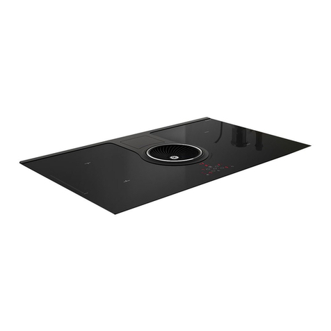
ELICA NIKOLATESLA ONE Technical manual

ELICA
ELICA NIKOLA TESLA FLAME Technical manual

ELICA
ELICA NIKOLATESLA ONE HP BL/F/G5 Technical manual

ELICA
ELICA FDS 100 User manual

ELICA
ELICA NIKOLA TESLA FLAME User guide

ELICA
ELICA NIKOLATESLA FIT Technical manual

ELICA
ELICA FLAME GR/A/88 Technical manual
ELICA
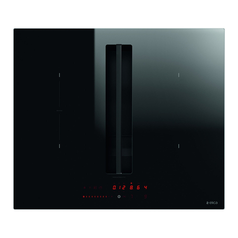
ELICA NikolaTesla FIT 60 Technical manual

