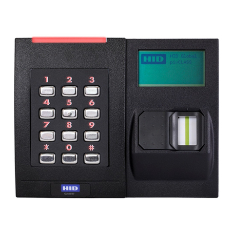
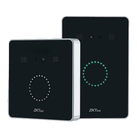
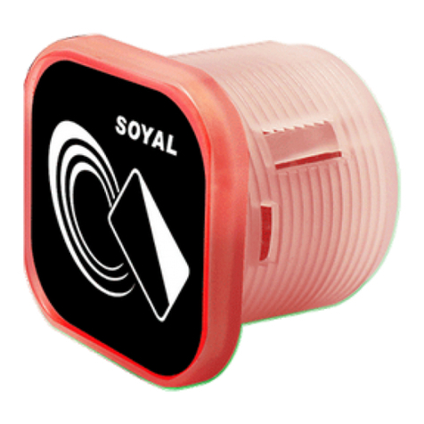
Elid EL2700 User manual

EL2700
IP-BASED ACCESS CONTROL
SYSTEM
USER MANUAL
(REVISION 1.0.0)
ELID SDN BHD
EL2700 IP-Based Access Control System

Table of Contents
TABLE OF CONTENTS ...........................................2
1. INSTALLATION....................................................... 1
2. STARTUP THE CONTROLLER............................5
3. PROGRAMMING MENU.......................................8
4. WEB SERVER MENU INTRODUCTION.............41

EL2700IP-Based Access Control System
User Manual
Revision 2.0 1
EL70Y /
EL70W
Hub
WAN / LAN
Hub
EL2700
EL2700
EL2700
Hub
EL2700
CHAPTER 1
1. INSTALLATION
1.1 SYSTEM CONFIGURATION
1.1.1
LAN Configuration

EL2700IP-Based Access Control System
User Manual
Revision 2.0 2
EL2700
Controller
Option 1:
EK848
EA62
Option 2:
EA62
EK847
EA62
Option 3:
ERM845
Option 4:
EA45
Wiegand
Reader
1.1.2
Configuration Overview
Important Note:
1. EL2700 can connect maximum up to 8 units of reading devices
with combination of EK847, EK848, ERM845, Syrisand EA45.
2. The last unit of reading device has to be terminated.
3. EL2700 can connect maximum up to 3 units of EA62 I/O board.

EL2700IP-Based Access Control System
User Manual
Revision 2.0 3
1.2 DEVICE COMPONENT
Device
Component
Description
EL2700
Controller
The main intelligent controller responsible for
accesses verification and card reading, installed
in secured area.
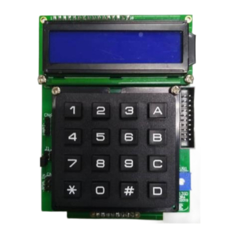
EK13SKeypad
This board consists of 2 by 16 LCD display
and 4x4 keypad. It is only required when you
cold start the controller and setting of IP
address and card type. EL2700 can run
normally without this board and thus it is an
optional board.
Power Supply
The standard power supply for EL2700 is
EP42S, 12V/4.2A switching power supply.
Reading Devices
There are various models of readers:
ER0748R:
EK748R/EM RS485 Touch
Sense Keypad with blue GLCD
Display
ER0723R01
ER723 RS485 Reader
ER0728R01
ER728 RS485 Reader
EA45
Wiegand tp RS485 reader
onverter. If you are using EM,
HID or Mifare reader with
wiegand output, you may need
this converter to convert the
signal.
EA62 I/O Board
The board allows connection of external sensor
and output appliance devices. It consist of 8
supervised inputs and 4 relay outputs

EL2700IP-Based Access Control System
User Manual
Revision 2.0 4
1.3 JUMPER SETTING
There are 2 jumpers to set at EL2700 before startup:
1. PIN 3 of JP567 (Batteryshunt)
The controller is shipped to you with the shunt “OFF”. You should put
this to “ON”, otherwise, memory will be lost each time you turn off
power to the controller.
2. JP11 (RS485 terminate for devicebus)
The both end of the RS485 devicebus must be always terminated.
Therefore, JP11 must be always shorted. Please note that the last
device in the RS485 device bus also has to be terminated.

EL2700IP-Based Access Control System
User Manual
Revision 2.0 5
Cold starting…
01 JAN 00 [MON]
00:00:00
CHAPTER 2
2. STARTUP THE CONTROLLER
2.1 POWERING UP EL2700
Warning: 12V Power inlet is at CN1 of EL2700 board; ensure
correct wiring and shunt the JP567 PIN3 battery jumper. The
controller is shipped to you with the shunt “OFF”. You should put this
to “ON”, otherwise, memory will be lost each time you turn off power
to the controller.
When using EL2700 for the first time, use steps below to carry out a
cold start in order to restore all settings and memory buffer to
factory default setting.
•Hold down key ‘A’on the keypad and press ‘reset’ button.
•Release the ‘reset’ button first then only release the ‘A’
keys after 3 seconds.
•Immediately upon release the ‘A’ keys, the display will
show:-
•Wait until the controller system finished its processes and
display date and time. Cold start is done

UserManual
EL2700IP-Based Access Control System
Revision 2.0 6
2 . 2 KEYPAD USAGE AND MENU SELECTION
EL2700 Keypad Layout
A(LEFT) and D(RIGHT)
To scroll through main
functional menus / go to next
setting in sub-menu
B (UP) and C (DOWN)
To scroll through sub-menu
of programming menu
(ESC)
To exit from a sub-menu
level back to main menu
*
# (ENTER)
To enable getting into sub-
menu level as well as
confirming entered value

EL2700IP-Based Access Control System
User Manual
Revision 2.0 7
01 JAN 00 [MON]
00:00:00
128.100.28.3
Unit: 01 to 04
EL2700V100
27 AUG 2021
Readers
x o o x - o - o
2.3 MAIN DISPLAY
Under normal operation, EL2700 display is showing date/time
information. However, user can navigate through the main display
information by using ‘C’ button. Currently, supported displays are
as follows:
a) Date and Time
b) IP address and unitnumber
c) Reader status
d) Firmware version and releasedate
Note: In reader status display, each symbol representing
connection status for one 485 reader/keypad. First symbol for
reader#1, second symbol for reader #2 and so on.
x : Reader connection down
o : Reader connected
- : Reader not assigned

EL2700IP-Based Access Control System
User Manual
Revision 2.0 8
Enter Mstr Pin
******
CHAPTER 3
3. PROGRAMMING MENU
3.1 GETTING INTO PROGRAMMING MENU
Press key ‘D’ , key in 6 digits master PIN when requested. Default
master PIN after cold start is 123456.
3.2 EL2700 MENU TREECHART
Time Menu
Date
Time
Holiday
Timer
Timezone
Comm. Menu
Comm. Method
Unit Number
IP Addr
Subnet Mask
Gateway
Port Setting
MAC Address
Clover Unit No
Clover CC No
Reader Menu
Reader Format
View Reader
Set ID
Repoll All Rdr
Card Menu
Add Card
Add Card w Pin
Del. Card
Clear DB

EL2700IP-Based Access Control System
User Manual
Revision 2.0 9
Date [DD/MM/YY]
01/01/01 MON
Door Menu
L.R Time
P.L.R
Card+PIN
Inhibit Acc
Cont. Swipe
Exit Push Buttn
Anti PB
Rst APB
APB Rst Tmr
PIN Only
DS
Debounce
PIN Dis TZ
L.R. TZ
Double Swipe
Exit Door TZ
Trans Menu
Print Trans
Clear Trans
I/O Menu Output1 TZ
Output2 TZ
O/P Type
System Menu
Change Master PIN
Reset Web Password
Test Menu
Test Output
Test Input
Test Keypad
Test Memory
Test Comm
3.3 TIME MENU
There are 5 commands under this menu which is Set Date, Set
Time, Holiday, Set Timer and Set Timezone.
You can use ‘B’ (up) or ‘C’ (down) key to scroll through the 4 sub-
menu.
3.3.1
Set Date
On selecting this menu, the following screen will be shown:

EL2700IP-Based Access Control System
User Manual
Revision 2.0 10
Holiday
#01 M:00 D:00
Date [DD/MM/YY]
SET SUCCESS!
Time [hh:mm:ss]
07:31:50
The cursor will blank at the day field, you may key in the new value.
When it’s done, the cursor will jump to month field. Enter a new
value and do the same to year field. Weekday will be calculated
automatically based on the date entered. Press <#> to save the
setting.
Upon successful of setting, the following screen will be shown
before it is back to TimeMenu.
3.3.2
Set Time
The following display is shown when you enter Set Time menu.
Enter hour field with a 2 digit value. The hour value is in 24 hours
format (e.g. 4 p.m is entered as 16 hour). Enter a value for minute
and seconds as well.
Finally, press <#> to save the setting. Note that you can press
< > anytime to abort and return back to Time Menu.
3.3.3
Set Holiday
EL2700 may be programmed to recognize holidays. During holiday,
a different set of time zones may be activated. A total of 20 holidays
may be preprogrammed using Set Holiday Menu as shown below:
Holiday number
(From 1 to 20) Month value Day value
*

EL2700IP-Based Access Control System
User Manual
Revision 2.0 11
Holiday
#02 M:00 D:00
The display above shows the cursor blinking at the month field. Any
valid month value may be entered. E.g. for January, enter 01.
The cursor will then jump to the Day field. Any valid value may be
entered. E.g. 01 for the first day and press the <#> Key.
The second Holiday will now be displayed: -
You may enter the second holiday. Note that if you have made a
mistake in entry, you can use the <B> Key to correct the value. You
can go back to the previous holiday number by using the ‘B’ Key or
you can skip to the next holiday by usingthe ‘C’ Key. When you
have finished entering all the holidays, leave the unused holiday
number with values 00, and press the < > Key to exitfrom this
command.
It is a good idea to check all your entries again after you have
completed your entry.
Table 3.1
HOLIDAY #
MONTH
DAY
REMARKS
1
01
01
New Years Day
2
05
01
Labor Day
3
08
31
National Day
4
12
25
Christmas Day
5
00
00
-
6
00
00
-
.
.
.
.
.
.
.
.
.
.
.
.
20
00
00
-
*

EL2700IP-Based Access Control System
User Manual
Revision 2.0 12
Timer
Door 1
3.3.4
Set Timer
EL2700 caters for 24 sets of timers for each door where 22 sets
are programmable. Each set consists of 2 pairs start time and end
time. Timer 1 is pre-defined as ‘No Entry Timer’ and Timer 2 is
pre-defined as ‘Free Entry Timer’. The timers are used in other
commands to set time zones.
They may be represented in the form of a table. In fact, users
should first of all consider the working hours of their establishment
and draw out a table such as that shown below before proceedingto
program the valuesin. Table 3.2
TIMER #
SET 1
SET 2
Start
End
Start
End
01
00:00
00:00
00:00
00:00
02
00:00
23:59
00:00
00:00
03
07:00
19:00
00:00
00:00
04
08:00
12:00
13:00
17:00
05
07:00
08:00
17:00
18:00
06
18:00
23:59
00:00
06:00
.
.
.
.
.
.
.
.
.
.
24
.
.
.
.
On entering into Set Timer menu, the following appears on the
display.

EL2700IP-Based Access Control System
User Manual
Revision 2.0 13
Timer [D1#01-2]
00:00
→
00:00
Use ‘B’ and ‘C’ key to select which door to set and press
<#>. The display shown as below:
Door
number Timer#
(1 to 24) Set number
(Set 1 or Set 2)
With the cursor blinking at the start time, hour field, enter the desired
value for start time hour field followed by start time minute field. The
cursor will jump to the end time hour field. Continue to enter the
values desired for end time hour field and end time minute field.
Press <#> to save setting. The display now will show the following
set (set 2).
Set 2
Continue to enter the values desired until all the times necessary for
your use have been programmed. Leave the unused times with the
default value of 00:00.
Note that you can skip from one screen to the next by using the ‘B’
and the ‘C’ Keys.
To abort Set Timer Command press the < > key once.
Timer [D1#01-1]
00:00
→
00:00
Start Time
Hour:Minute
End Time
Hour:Minute
*

EL2700IP-Based Access Control System
User Manual
Revision 2.0 14
Timezone
Door 1
3.3.5
Set Access Time Zone
This command allows you to associate the timers, which you have
programmed in Section 3.3.4 with each Access Time Zone. There
are a total of 10 Access Time Zones. Each with a programmable
timer for each day of the week and holiday. In table form, it may be
represented as follows: -
Table 3.3
ACCESS TZ
TIMERS FOR
Sun
Mon
Tue
Wed
Thu
Fri
Sat
Hol
1
01
01
01
01
01
01
01
01
2
03
02
02
02
02
02
02
03
3
.
.
.
.
.
.
.
.
4
.
.
.
.
.
.
.
.
.
.
.
.
.
.
.
.
.
.
.
.
.
.
.
.
.
.
.
.
.
.
.
.
.
.
.
10
.
.
.
.
.
.
.
.
Time Zone 1 is pre-defined as ‘No Entry Time Zone’ and TimeZone
2 is pre-defined as ‘Free Entry TimeZone’
On entering this command, the following screen appears: -
Enter the desired door to access Time Zone menu for that particular
door as shown below:

EL2700IP-Based Access Control System
User Manual
Revision 2.0 15
Timezone [D1#01]
MON: 01
Timezone [D1#02]
SUN: 00
Door Acc TZ
(1 To 10)
Enter the desired timer value. These values refer to the timer
settings described in Section 3.3.4 and can be any from 1 to 24.
Note that the value 00 is reserved forNo access.
After setting the timer value for Sunday, press <#>, the next
screen is shown for Monday.
Then continue for Tuesday, Wednesday, Thursday, Friday,
Saturday, and Holiday.
After that the second Access Level is shown: -
Users can continue entering the decimal values for up to 10 Access
Levels.
Note that the ‘B’ and the ‘C’ Keys may be used to jump back to the
previous display screen or to skip to the following display screen.
To escape from this command, press the < > Key.
Timezone [D1#01]
SUN: 01
Day of the
week
Timer #
(1 To 24)
*

EL2700IP-Based Access Control System
User Manual
Revision 2.0 16
Set IP
128.100.028.003
Comm. Method
BR9600
Set Unit No.
1 2 3 4
3.4 COMMUNICATION MENU
3.4.1
Set Communication Method
The factory setting is “Ethernet Comm”. You can change the baud
rate to any of the following 2400, 4800, 9600, 19200, and Ethernet
Comm by pressing ‘B’ and ‘C’ key. When the desired setting is
displayed, press the <#> Key to accept.
If you wish to use LAN communication, please select Ethernet
communication. If you are using either RS485, you may choose
the baud rate from 2400 to 19200.
3.4.2
Set Unit Number
Unit number is the identification number of controller. Since EL2700
is a four doors controller, it unit number is in sets of 4. You can only
choose 1 set from 4 sets of unit number, ‘1 2 3 4’, ‘5 6 7 8’, ‘9 10
11 12’ or ’13 14 15 16’.
The screen looks like this: -
Change the displayed unit number by pressing ‘B’ and ‘C’ key.
When the desired setting is displayed, press the <#> Key to
accept.
3.4.3
Network Parameters
The other commands are related to LAN communication, you can
modify their value according to your local LAN setting as shown
below:

EL2700IP-Based AccessControl System
User Manual
Revision 2.0 17
Set Gateway
128.100.001.002
Port Setting
Port: 04001
MAC Addr
0C:EE:E6:00:00
Clover Unit No
C-UN: 00001
Clover CC No
C-CC: 00001
Please check with the network administrator on what values to set
and key in these values.
3.4.4
MAC Address
Display MAC Address of EL2700.
3.4.5
Clover Unit No.
To set Clover System unit number. Can set until 999.
3.4.6
Clover CC No.
To set Clover System Customer Code unit number.
Set Netmask
255.255.000.000

EL2700IP-Based AccessControl System
User Manual
Revision 2.0 18
Offs Len Max
20 20 40
3.5 READER MENU
3.5.1
Reader Format
Depending on the type of readers you are using, you should set to
the appropriate card format.
On entering this menu, the display as below appears:
You can change the card type by pressing ‘B’ and ‘C’ key. The
various types of readers that you can select are: -
Wiegand Wiegand Reader, with 26 bit Wiegand format
F Wiegand Free Wiegand Reader, with 40 bit format
ELID HID Proximity Reader, with ELIDformat
When the desired setting is displayed, press the <#> Key to
accept.
If Free Wiegand format is selected, the display will show as follow:
Offset bit Card bit Card Size
There are 3 fields for setting which is:
Offset Bit Set offset bit
Card Length Bit Set No. of bit as card
Card size Max number of bit for card reading
(maximum 40bits)
Example:
Reader Format
Wiegand
Other Elid IP Access Controllers manuals

