Eliminator 011-2014-0 User manual
INSTRUCTION
MANUAL
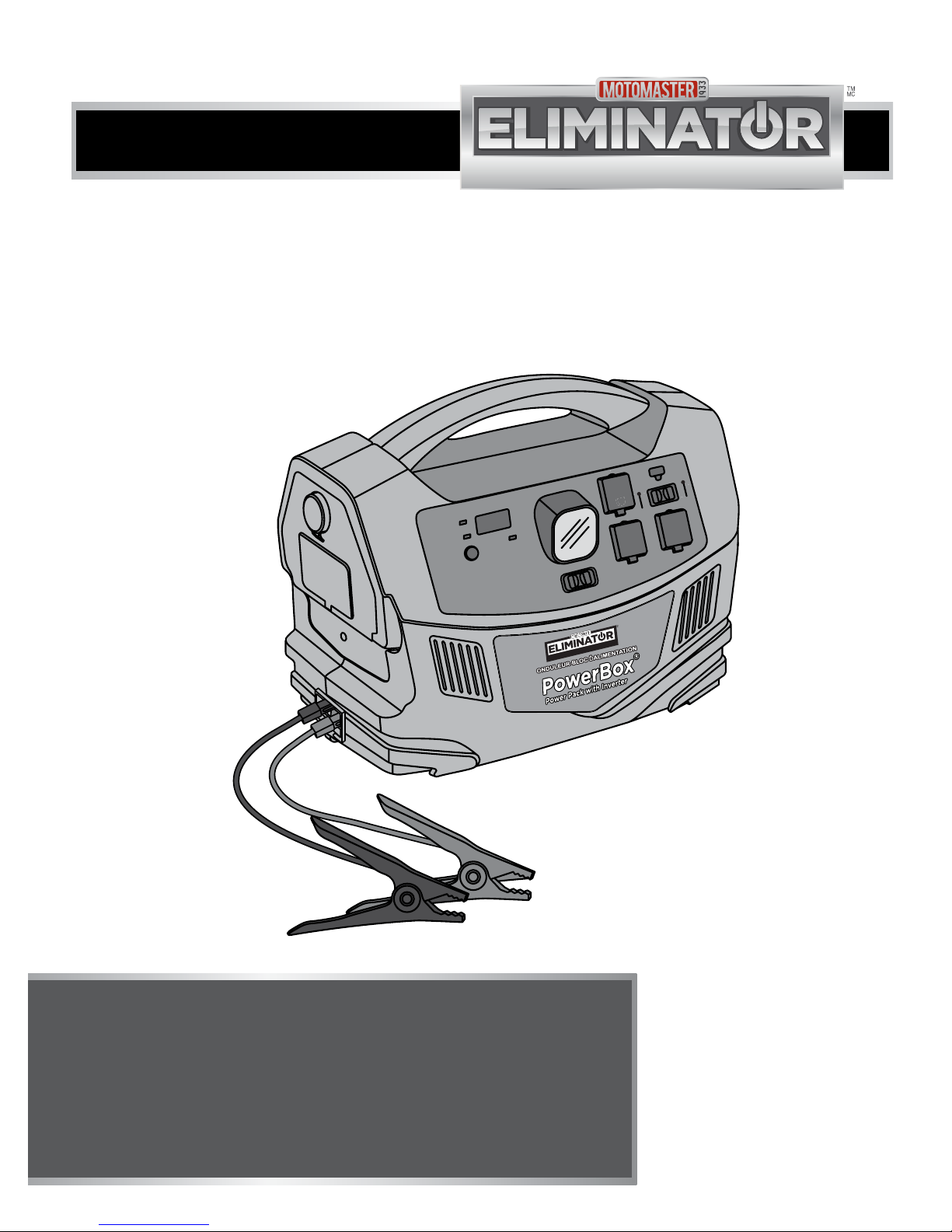
POWER PACK WITH
INVERTER
model no. 011-2014-0
IMPORTANT:
This manual contains important safety and
operating instructions. Read all instructions and
follow them with use of this product.
Charging status
Ètat de la charge
Digital Display Button
Bouton ďachage
numérique
Outout power Indicator
Voyant de la puissance
de sortie
Battery Capacity (%)
USB Port
011-2014-0
011-2014-0
600 W
Prise USB
LED Switch
FR. LED Switch
Adaptaeur
CA
AC
Adapter
AC/USBOn Indic ator
Voyantďutilisation
de la prise USB/CA
USB On Indicator
OFF/ARRÊT
Voyantďutilisation
de la prise USB
Capacité de la
batterie (%)
12 V DC
SOCKET
8. 8. 8

2
3
model no. 011-2014-0 | contact us 1-877-619-6321
DO NOT RETURN THIS PRODUCT TO THE STORE!
QUESTIONS? CALL CUSTOMER SERVICE, HOTLINE: 1-877-619-6321
TABLE OF CONTENTS
TABLE OF CONTENTS
Safety Information 4
Key Parts List 10
Important Information 12
Operation 20
Maintenance 33
Troubleshooting 34
Technical Specification 38
Warranty 40

4
model no. 011-2014-0 | contact us 1-877-619-6321
SAFETY INFORMATION
SAFETY INFORMATION
This manual contains information
that relates to protecting personal
safety and preventing equipment
problems.
Carefully read and follow the
guidelines in this manual and give
special attention to the caution and
Warning statements.
ABBREVIATIONS AND
ACRONYMS
A Amp (Ampere)
AC Alternating current
Ah Amp-hours
DC Direct current
LED Light emitting diode
mm Millimeter
cm Centimeter
V Volts
W Watts
mA Milliampere
EXPLOSION AND FIRE
HAZARD
• Do not use the power pack with
life support systems or other
medical equipment or devices.
SHOCK AND FIRE
HAZARDS
• Keep children away from the
power pack, as the AC power
generated by the power pack
is as lethal as a normal wall
outlet.
• Do not expose the power pack
to water, rain, snow, spray, or
condensation.
• Make sure the power pack
wiring is of proper size and
rating and in good condition.
Operating the power pack
with damaged wiring may void
warranty.
• Do not use the power pack if it
is dropped, hit, worn, broken or
damaged.
• Do not attempt to service or
disassemble the power pack,
as it does not have user-
serviceable parts.
• Disconnect the power source
from the power pack, before
attempting to clean or operate
the power pack. Turning OFF
the power pack does not reduce
the risk of electric shock.
• Do not open the power pack
and attempt to replace the
internal battery.
• Have a qualified technician
perform any service work.
• Do not insert any foreign objects
into the outlets, vents, or fan
openings of the power pack.
FIRE HAZARD
• Do not cover or obstruct the
ventilated openings of the
power pack, as doing so may
cause overheating.
• Make sure there is a minimum
of 3” (7.5 cm) of unblocked air
space around the entire surface
of the power pack at all times.
• Keep the power pack away from
materials that can be affected
by high temperatures such as
blankets, pillows and sleeping
bags.
EXPLOSION AND FIRE
HAZARD
• Never operate the power
pack near flammable items or
explosives, such as in cabin
of a gasoline powerboat, or
near propane/fuel tanks, in
compartments containing
batteries of flammable
materials, locations that
require ignition-protected
equipment, joints, fittings or
any connections between fuel
system components.
• Make sure the area around
the battery and engine is well
ventilated and free from spark
or flame.
• Do not operate the power pack
in an enclosed area containing
automotive type lead-acid
batteries. This type of batteries
emits explosive hydrogen gas
that can be ignited by sparks.
5
SAFETY INFORMATION
IMPORTANT!
Read and keep this owner’s manual for future reference. This chapter contains
important safety instructions.
Charge the power pack immediately after purchase for atleast 48 hours and
recharge the unit after every use. Recharge the unit once every 90 days, even if
the power pack is not in use. Failure to comply will void the warranty.

6
7
model no. 011-2014-0 | contact us 1-877-619-6321
SAFETY INFORMATION
SAFETY INFORMATION
• Do not allow the clamps of
the boosting cable to touch
each other or another common
conductor, as it causes sparks
and / or damages the equipment.
• Always connect the clamps to
the correct terminals. A reverse
polarity connection damages the
unit and / or creates a spark or
explosion.
• DO NOT use DC to DC charging
cable to charge power pack if
your vehicle’s electrical system
operates above 15 V. This
may lead to accumulations of
hydrogen, causing exposure to
fire and explosion hazards. This
condition is typically found in
marine appliances or portable
generators with DC output.
• When working on electrical
equipment, always ensure
someone is nearby to aid you in
case of emergency.
EQUIPMENT DAMAGE
• Do not connect the power pack
to any AC device with neutral
conductor connected to ground,
as doing so may damage the
power pack.
• Do not expose the power pack
to temperatures over 104° F
(40° C).
• Do not allow the positive and
negative clamps of the boosting
cable to touch each other
or another common metal
conductor. Doing so may cause
sparks and/ or damage the
equipment. Always store the
boosting cables separately after
use.
• Make sure the positive clamp of
the boosting cable is connected
to the positive terminal of the
battery and the negative clamp
is connected to the negative
terminal of the battery. A
reversed polarity connection
(positive to negative) may
cause sparks or damage the
equipment.
• Do not use the boosting feature
for more than 5 seconds, as
it is designed for short term
operations only. Doing so may
damage the equipment. Allow
the power pack to cool for
at least 3 minutes after each
boosting operation.
SAFETY PRECAUTIONS
WHEN WORKING WITH
BATTERIES
Follow all instructions mentioned
by the manufacturer to avoid
explosion of the battery.
SHOCK AND FIRE HAZARD
• Do not operate the power
pack in an enclosed area
containing automotive type
lead-acid batteries. These
batteries, unlike the sealed AGM
battery in the power pack emit
explosive hydrogen gas that
can be ignited by sparks from
electrical connections.
• Do not work near lead-acid
batteries, as the batteries
generate explosive gases during
normal operation.
• Make sure the area around
the battery or engine is well
ventilated and free from spark
or flame.
• Do not drop a metal tool on the
battery, as doing so can create
spark or short circuit in the
battery or other electrical parts,
resulting in battery explosion.
• While removing the battery,
make sure to remove positive
terminal from the battery and
disconnect other electrical
connections.
• Always have assistance nearby
when working with the lead-
acid batteries.
• Do not use this device to charge
nickel cadmium batteries.
• Never smoke while handling the
power pack or the batteries.
CHEMICAL HAZARD
• Remove all metal items such as
rings, bracelets, and watches
when working with lead-acid
batteries. The batteries may
produce short circuit current
that can weld metals, thereby
causing severe burns on skin.

8
model no. 011-2014-0 | contact us 1-877-619-6321
• Make sure there is plenty of
fresh water and soap near the
work area. If a person’s skin or
clothing accidentally contacts
with battery acid, wash
immediately with soap and
water. If the acid enters eyes,
wash immediately with running
cold water for a minimum of
twenty minutes and get medical
attention immediately.
• Always wear complete eye
and clothing protection. Avoid
touching your eyes while
working with the batteries.
• Always keep baking soda on
hand for emergency purposes,
as it neutralizes the lead-acid
battery electrolytes.
• Recycling of the battery is
recommended to prevent
inappropriate disposal of the
battery.
SAFETY PRECAUTIONS
WHEN USING
RECHARGEABLE
APPLIANCE
Most rechargeable battery-
operated equipment uses a
separate charger or transformer
that is plugged into an AC
receptacle and produces a low
voltage charging output. Some
chargers for small rechargeable
batteries can be damaged if
connected to this Power Pack.
EQUIPMENT DAMAGE
• Do not use this power pack to
charge small battery operated
appliances such as flashlights,
razors, and night lights that can
be plugged directly into an AC
outlet.
• Do not use this power pack
for certain battery chargers
of battery pack used in hand
power tools (with nickel
cadmium batteries). The
battery chargers provided for
the tools will have a warning
label indicating that the battery
terminals contain dangerous
voltage.
SAFETY INFORMATION
9
BATTERY RECYCLING
The Power Pack is durable. However, the internal batteries are not user
replaceable.
The internal batteries contain lead, which can be hazardous if
exposed to environment. The battery should be recycled or safely
disposed at your local recycling depot. Do not dispose of the
battery or Power Pack with regular household waste. Contact your
local authorities for recycling services.
SAFETY INFORMATION
• In case of difficulty in using your
rechargeable appliance with the
Power Pack, contact the equipment
manufacturer to determine the
rechargeable appliance’s compatibility
with the modified sine wave (non-
sinusoidal) AC waveform.
• Make sure the power pack is turned
OFF when not in use, to prevent
unnecessary battery discharge.
10
11
model no. 011-2014-0 | contact us 1-877-619-6321
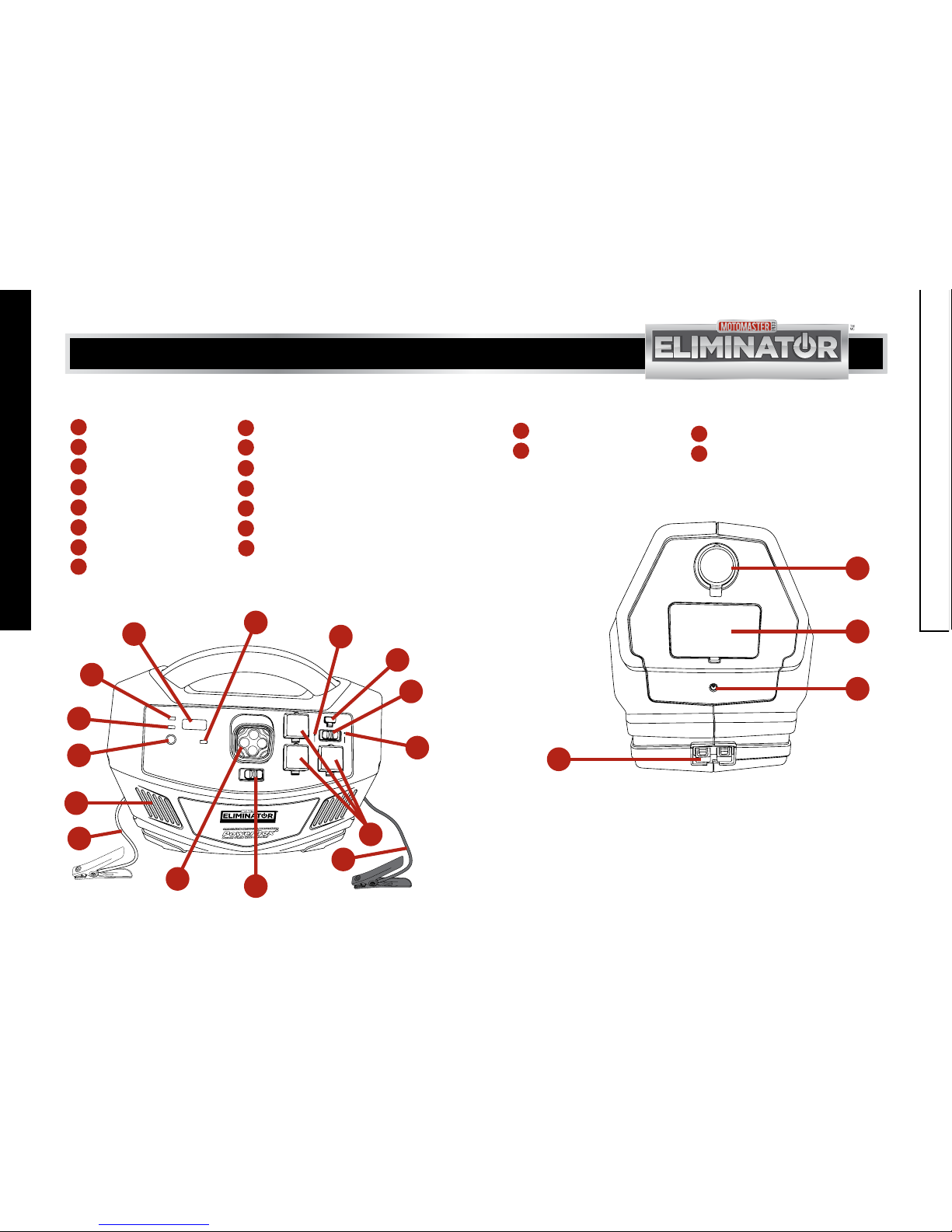
FRONT PANEL
1
8
2
9
3
10
4
11
5
12
6
13
7
14
15
AC/USB indicator Positive boosting cable
USB port Ventilation opening
AC/USB switch Digital display button
USB ON indicator Output power indicator
AC outlets Battery capacity % indicator
Negative boosting cable Digital display
LED switch
LED light
Charging indicator
Voyant ďutilisation
de la prise USB
Voyant ďutilisation
de la prise USB/CA
USB On Indicator
OFF/ARRÊT
USB Port
Prise USB
011-2014-0
011-2014-0
AC/USB On Indicator
LED Switch
FR. LED Switch
Charging status
Output power indicator
Battery Capacity (%)
Capacité de la batterie (%)
Digital Display Button
Bouton ďachage numérique
Voyant de la pulssance de sortie
État de la charge
8. 8. 8
600 W
MM-112014-01
1
2
3
4
5
6
7
8
9
10
11
12
13
14 15
SIDE PANEL
18
19
16
17
AC charging input port
Boosting cable port
12 V DC outlet
250 A fuse
12V DC
SOCKET
Adaptateur
CA
AC
Adapter
MM-112014-02
16
17
18
19
KEY PARTS LIST
KEY PARTS LIST
12
model no. 011-2014-0 | contact us 1-877-619-6321
13
GENERAL USE
The MotoMaster®Eliminator power
pack is easy to use and designed
for years of reliable service. The
MotoMaster®Eliminator power
pack can run AC and 12 V DC
appliances and also can be used to
jump start engines.
SAFETY FEATURES
These safety feature ensure safe
and trouble free operation of the
power pack.
AUDIBLE ALARM - The alarm
produces an audible sound when
the battery reaches 11 V DC.
Turn the power pack OFF after
disconnecting all AC and DC
loads. If the warning is ignored the
power pack will automatic shut
off to avoid damage battery. The
alarm also sounds when internal
circuits temperature is high. When
this happened, the power pack
will automatic shut off to protect
the internal circuits from being
damaged. The alarm also sounds
if there is a reverse connection
between the boosting cables and
battery.
OVERLOAD SHUTDOWN - This
feature automatically shuts down
the power to AC outlet within
15 seconds, in case of an overload
(>600 W).
POWER PACK
COMPONENTS
AC/USB INDICATOR - The
indicator indicates both the AC
and USB are available.
USB PORT - The USB port
supplies 5 V 2100 mA of power.
NOTE:
If a high capacity load is not removed from the AC outlet of the power pack immediately after
this shutdown, the power pack will shut OFF and then turn ON again and again. This will lead
to ON-OFF-ON-OFF condition which could be noticed through wattage displayed in the digital
display. It is recommended to disconnect the load from the AC outlet immediately after the
occurrence of overload shutdown. The power pack will then automatically resume its operation.
AC/USB SWITCH - When this
switch is slid to the right,
the USB power indicator glows
to indicate that the power can
be delivered to the electrical
appliances through USB port. If this
switch is slid to the left, the AC /
USB indicator glows to indicate that
the AC outlets and USB port are
available. If the switch is in middle,
power will be disconnected from
both the USB port and AC outlet.
USB ON INDICATOR - This
indicator lights up if the AC/
USB slide switch is slid to the right
and power is available in the USB
power port only.
AC OUTLET - The power pack
is provided with three standard
3-prong outlets through which
115 V AC power can be delivered to
AC appliances.
NEGATIVE AND POSITIVE
BOOSTING CABLES - These
cables , are connected to
engine battery of vehicle, when the
power pack is used to jump start
a vehicle. Make sure the positive
and negative cable clamps are
connected to the positive
and negative battery terminals,
respectively.
LED SWITCH - This switch is a
simple ON-OFF slide switch. Slide
this switch forward to turn ON the
white LED light and backward to
turn OFF the white LED light.
LED LIGHT - The light is used
for lighting purposes during an
emergency situation. It is not the
regular LED light.
VENTILATION OPENING - This
opening protects the power
pack from overheating.
DIGITAL DISPLAY BUTTON - This
button turns ON/OFF the digital
display. When the button is pressed,
the digital display indicates battery
capacity % status.
OUTPUT POWER INDICATOR -
This indicator glows green
when the output power information
is displayed on the digital display.
BATTERY CAPACITY %
INDICATOR - The indicator
glows green when the battery
charge information is displayed on
the digital display.
1
3
4
5
6 9
8
10
11
12
13
2
7
IMPORTANT INFORMATION
IMPORTANT INFORMATION

14
15
model no. 011-2014-0 | contact us 1-877-619-6321
DIGITAL DISPLAY - This feature
displays the output power in
watts and the battery charge status
in percentage.
CHARGING INDICATOR - This
indicator will flash green
intermittently when the battery is
charging and glows green when the
battery is fully charged.
12 V DC OUTLET - The outlet
powers 12 V DC auto, RV or marine
appliances. The outlet can also be
used to recharge the unit using the
DC to DC charging cable.
250 A FUSE - The fuse
protects the power pack from
damage due to reverse connection
and short circuit. It is strongly
recommended to avoid reverse
connection of the booster cables
with the battery terminals.
AC CHARGING INPUT PORT - The
port through which the AC
charger can be inserted to charge
the battery of the power pack.
BOOSTING CABLE PORT - The
port through which the
boosting cables are connected
to supply high power DC current,
when boosting a vehicle’s battery
or when connecting an external
battery to the power pack. The
boosting cable connection is
designed in such a way that the
boosting cables cannot be inserted
incorrectly into the power pack.
IMPORTANT INFORMATION
IMPORTANT INFORMATION
17
14
15
16
18
19
NOTE:
• It is recommended to detach the DC to DC charging cable from the unit and vehicle as
soon as the battery is fully charged or if the vehicle’s engine is turned off. DO NOT leave
the power pack permanently connected to the vehicle’s 12 V accessory outlet.
• It is recommended to use the power pack to charge 12 V accessories less than 12 A.
• It is recommended to use only the AC charger provided for charging the internal battery.
This charger has protection function. Do not use cable clamps to charge the internal
battery.
TROUBLE LOADS
The output of this power pack
is non-sinusoidal. The electrical
appliances mentioned below will be
damaged when connected to this
power pack.
• Electronics that modulate RF
(radio frequency) signals on the
AC line will not function and
may be damaged.
• Speed controllers found in
some fans, power tools, kitchen
appliances, and other loads may
be damaged.
• The chargers used for small
nickel cadmium rechargeable
batteries may be damaged.
• Metal halide arc (HMI) lights will
be damaged.
HIGH SURGE LOADS
Some induction motors used in
freezers, pumps, and other motor
operated equipment need high
surge current to start. This power
pack may not be able to start these
motors even though their rated
current is within the power pack’s
limits. The power pack will start
single phase induction motors rated
at horsepower of 1/2 or less.
NOTE:
• In case of difficulty in using your rechargeable appliance with the power pack, contact our
customer support at 1-877-619-6321 between 9:00 am to 5:00 pm PST.
• Even though the power pack can supply momentary surge power up to 1,000 W, some
appliances may exceed capabilities of the power pack and trigger the safety overload
shutdown circuit. This shutdown is intermittent. The power pack will automatically restart
and shutdown until the load does not exceed the surge rating. It is recommended to check
the output of your appliance.

16
17
model no. 011-2014-0 | contact us 1-877-619-6321
IMPORTANT INFORMATION
IMPORTANT INFORMATION
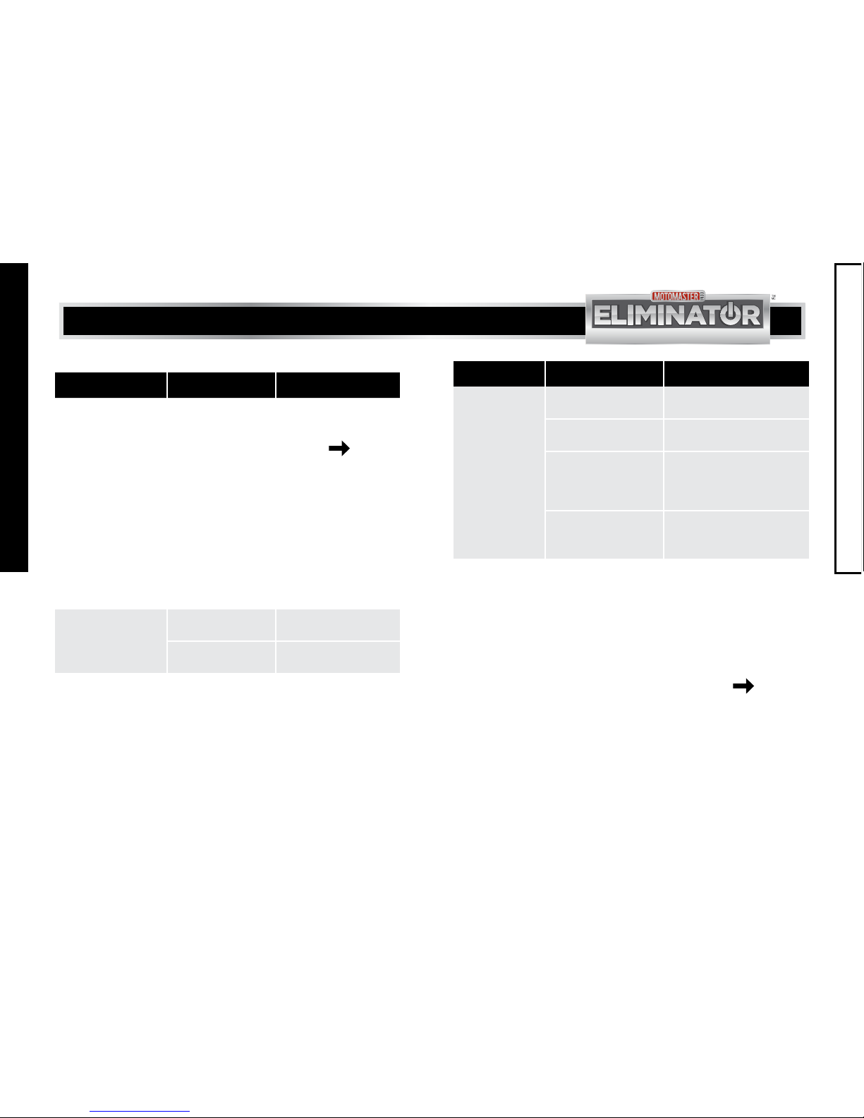
AC APPLIANCE WATTS* HOURS
Cordless telephone (stand by) 5 56 h**
Clock radio 8 35 h**
Portable stereo 10 28 h**
Fluorescent work light 14 20 h**
Laptop computer 40 5 h 30 min**
Table lamp 40 5 h 30 min**
13” colour television 60 3 h 20 min**
3/8" drill 190 50 min**
5” random orbital sander 276 30 min**
AC APPLIANCE WATTS* HOURS
Mobile phone 6 46 h***
Fluorescent light 8 35 h**
Portable cooler 30 10 h**
Portable vacuum cleaner 100 2 h 20 min**
Jigsaw 345 30 min
AC APPLIANCE RUN TIME
DC APPLIANCE RUN TIME
* Actual power consumption as measured on sample products.
** Operating times assume a fully charged 28 Ah battery and may vary based
on model/brand used.
*** Represents talk time available from 5 rechargeable cycles.
CONDITION DESCRIPTION
Dry Avoid splashing of water or other liquids on the power pack.
Keep the power pack away from damp or moist areas.
Temperature Maintain ambient air temperature between -32°F and 104°F
(0°C and - 40°C).
Ventilation Leave atleast 3” (7.5 cm) of clearance around the power
pack for airflow. Ensure that the ventilation openings are not
obstructed.
Safety Do not install the power pack in a compartment containing
batteries or flammable liquids like gasoline.
Flammable battery
gases
Do not mount the power pack in a place where it is exposed to
gases produced by the batteries. Prolonged exposure to these
gases will damage the power pack, as they are very corrosive.
POWER PACK LOCATION
The power pack should be operated only in locations that meet the following
requirements:

18
19
model no. 011-2014-0 | contact us 1-877-619-6321
IMPORTANT INFORMATION
IMPORTANT INFORMATION
PACKAGING CONTENTS
NO. MATERIAL NAME QUANTITY ILLUSTRATION
1Power pack with
inverter 1
2 AC charger 1
3 DC charging cable 1
4 Boosting cables 2
5 Owner’s manual 1
Charging status
Ètat de la charge
Digital Display Button
Bouton ďachage
numérique
Outout power Indicator
Voyant de la puissance
de sortie
Battery Capacity (%)
USB Port
011-2014-0
011-2014-0
600 W
Prise USB
LED Switch
FR. LED Switch
Adaptaeur
CA
AC
Adapter
AC/USB On Indicator
Voyant ďutilisation
de la prise USB/CA
USB On Indicator
OFF/ARRÊT
Voyant ďutilisation
de la prise USB
Capacité de la
batterie (%)
12 V DC
SOCKET
8.8. 8
NOTE:
If any of these materials are missing or damaged, please contact our TOLL-FREE,
Hotline: 1-877-619-6321.
1. Check battery capacity status by
pushing the digital display button
to ensure that the battery is fully
charged.
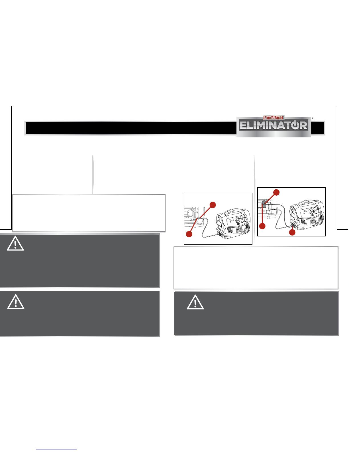
2. Open the AC outlet plastic
cover (1). Slide the AC /USB slide
switch (2) to the left. The AC/USB
indicator (3) will glow (fig A).
MM-112014-02
Charging status
Ètat de la charge
Digital Display Button
Bouton ďachage
numérique
Outout power Indicator
Voyant de la puissance
de sortie
Battery Capacity (%)
USB Port
011-2014-0
011-2014-0
600 W
Prise USB
LED Switch
FR. LED Switch
AC/USB On Indicator
Voyant ďutilisation
de la prise USB/CA
USB On Indicator
OFF/ARRÊT Voyant ďutilisation
de la prise USB
Capacité de la
batterie (%)
8. 8. 8
fig A
1
2
3
WARNING! SPARK AND EXPLOSION HAZARD
Do not operate the power pack in compartments containing batteries or
flammable materials, or in locations that require ignition protected equipment.
OPERATION OF AC
APPLIANCES
CAUTION! EQUIPMENT DAMAGE
• Read all operating instructions before operating the MotoMaster®Eliminator
power pack.
• Do not use the power pack to operate any AC appliances or 12 V DC
appliances while recharging the power pack battery with the AC Charger,
as the AC charger may fail if the appliances are being used while the AC
charger is connected.
• Do not use the power pack as an UPS (Uninterruptible Power Supply).

21
model no. 011-2014-0 | contact us 1-877-619-6321
20
OPERATION
3. Plug the power cord (1) of the AC
appliance into the AC outlet (2)
(fig B).
4. Turn ON the AC appliance.
5. Recharge the power pack
immediately after use. Refer to
Recharging the power pack with
AC charger pages 29-30.
MM-112014-03
Charging status
Ètat de la charge
Digital Display Button
Bouton ďachage
numérique
Outout power Indicator
Voyant de la puissance
de sortie
Battery Capacity (%)
USB Port
011-2014-0
011-2014-0
600 W
Prise USB
LED Switch
FR. LED Switch
AC/USB On Indicator
Voyant ďutilisation
de la prise USB/CA
USB On Indicator
OFF/ARRÊT
Voyant ďutilisation
de la prise USB
Capacité de la
batterie (%)
8. 8. 8
fig B
2
1
NOTE:
• In case of using many AC appliances, use an AC power bar for additional AC outlets. However,
for continuous operations, the combined loads must be less than 480 W. The power pack will
operate for a longer time on a single full charge if less wattage appliances are used.
• Some appliances may be difficult or impossible to operate using this power pack. They may
have high surge requirements or may be incompatible with the output waveform of this power
pack. Refer to Important information page 15.
CAUTION! EQUIPMENT DAMAGE
• Do not use equipments that require a pure sine wave power source, as the
output of the power pack is non-sinusoidal.
• The combined loads of the appliances must be less than 700 W for continuous
operations. The power pack operates longer on a single full charge when less
wattage appliances are used.
• Equipments with high surge requirements cannot be operated with the power
pack. Failure to comply may lead to equipment damage or personal injury.
OPERATION
1. Check battery capacity status by
pushing the digital display button
to ensure that the battery is fully
charged.
2. Open the 12 V DC outlet plastic
cover (1). Plug the power cord of
the DC appliance (2) into the
12 V DC outlet (3) (fig C).
MM-112014-04
Charging status
Ètat de la charge
Digital Display Button
Bouton ďachage
numérique
Outout power Indicator
Voyant de la puissance
de sortie
Battery Capacity (%)
USB Port
011-2014-0
011-2014-0
600 W
Prise USB
LED Switch
FR. LED Switch
Adaptaeur
CA
AC
Adapter
AC/USB On Indicator
Voyant ďutilisation
de la prise USB/CA
USB On Indicator
OFF/ARRÊT
Voyant ďutilisation
de la prise USB
Capacité de la
batterie (%)
8. 8. 8
12VDC
SOCKET
fig C
3
1
2
OPERATION OF 12 V DC
APPLIANCES
3. Turn ON the DC appliance.
4. Recharge the power pack
immediately after use. Refer to
Recharging the power pack with
AC charger pages 29-30.
NOTE:
• The 12 V DC outlet does not automatically turn off the power supply to the DC
appliance, even if the internal battery of power pack is discharged.
• Please disconnect the 12V DC appliances after use to avoid over discharge of power
packs internal battery.
• The power pack can charge auto, RV, or marine portable12 V DC appliance that draws
12 A or less through the 12 V DC outlet. While operating the DC appliance, the combine
load of the appliance including the power pack’s white LED light and USB port must not
exceed 115 W. The power pack will operate for a longer time on a single full charge if
less wattage appliances are used.

22
23
model no. 011-2014-0 | contact us 1-877-619-6321
OPERATION OF LED LIGHT
1. Slide the LED switch (1) of the
power pack to turn ON/OFF the
LED light (2) (fig F).
CAUTION! EQUIPMENT DAMAGE
Do not use the LED light regularly, as it is designed for use only in emergency
situations.
CAUTION! EQUIPMENT DAMAGE
• It is recommended to slide the AC/USB slide switch to the left when operating
a DC appliance. Turning ON this switch will enable the audible alarm feature
to produce an audible alarm when there is battery discharge. This will avoid
excessive discharge and damage to the battery.
• Never connect the USB power port directly to a computer USB outlet. Doing
so may cause damage to both the power port and USB outlet.
OPERATION
OPERATION
Voyant ďutilisation
de la prise USB
Voyant ďutilisation
de la prise USB/CA
USB On Indicator
OFF/ARRÊT
USB Port
Prise USB
011-2014-0
AC/USB On Indicator
LED Switch
FR. LED Switch
Charging status
Output power indicator
Battery Capacity (%)
Capacité de la batterie (%)
Digital Display Button
Bouton ďachage numérique
Voyant de la pulssance de sortie
État de la charge
8. 8. 8
fig F
MM-112014-15
2
1
MM-112014-06
Chargingstatus
Ètatdela charge
011-2014-0
600W
LEDSwitch
FR.LEDSwitch
AC/USBOnIndicator
Voyantďutilisation
delapriseUSB/CA
USBOnIndicator
OFF/ARRÊT
Voyantďutilisation
delapriseUSB
8
fig E
AC/USBOn Indicator
Voyantďutilisation
dela prise USB/CA
USBOn Indicator
OFF/ARRÊT
Voyantďutilisation
dela prise USB
2
1
3. Slide the AC /USB slide switch (1)
to the right. The USB power
indicator (2) will glow to indicate
that the USB power port is
activated (fig E).
4. Recharge the power pack
immediately after use. Refer
to Recharging the power
pack with AC charger
pages 29-30.
NOTE:
The USB power port of the power pack can only charge compatible devices like MP3 players,
PDAs, digital cameras, and camcorders that have internal batteries. NOTE:
Please slide the switch (1) to OFF after use. Failure to do so may damage the internal battery
because of over discharge.
2. Plug one end of USB cable (1)
(not provided) into the USB power
port and other end to the USB-
chargeable device e.g. MP3
player (2) (fig D).
MM-112014-05
Charging status
Ètat de la charge
Digital Display Button
Bouton ďachage
numérique
Outout power Indicator
Voyant de la puissance
de sortie
Battery Capacity (%)
USB Port
011-2014-0
011-2014-0
600 W
Prise USB
LED Switch
FR. LED Switch
AC
Adapter
AC/USB On Indicator
Voyant ďutilisation
de la prise USB/CA
USB On Indicator
OFF/ARRÊT
Voyant ďutilisation
de la prise USB
Capacité de la
batterie (%)
8. 8. 8
fig D
MEDIA
PLAYER
2
1
1. Check battery capacity status to
ensure the battery is fully charged.
Refer to Important information
page 11.
OPERATION OF USB DEVICES JUMP STARTING AN
ENGINE
The power pack can boost vehicle
or boat engine (all 4 cylinder type
and most 6 cylinder type) that has
a 12 V starting battery, using the
boosting cables.
1. Make sure your vehicle is a
negative ground system. If it is a
positive ground system vehicle
or unsure, pleased consult the0
vehicle owners manual.
2. Turn off the vehicle and other
accessories.
24
25
model no. 011-2014-0 | contact us 1-877-619-6321
7. Connect the ring terminal of the
negative (-) battery cable (black) to
the negative DC terminal (black) of
the power pack. Then connect the
negative (black) clamp (1) from the
power pack to the chassis (2) of
the vehicle (fig H).
OPERATION
OPERATION
MM-112014-08
Charging status
Ètat de la charge
Digital Display Button
Bouton ďachage
numérique
Outout power Indicator
Voyant de la puissance
de sortie
Battery Capacity (%)
USB Port
011-2014-0
011-2014-0
600 W
Prise USB
LED Switch
FR. LED Switch
Adaptaeur
CA
AC
Adapter
AC/USB On Indicator
Voyant ďutilisation
de la prise USB/CA
USB On Indicator
OFF/ARRÊT
Voyant ďutilisation
de la prise USB
Capacité de la
batterie (%)
12 V DC
SOCKET
8. 8. 8
fig H
+
1
3
2
NOTE:
• Ensure that the power pack is placed away from the moving parts of the engine and
jumpstart power switch is in OFF position.
• The positive (+) terminal of the battery is usually larger in diameter than the negative
terminal (-). The positive terminal (+) of the battery is usually connected with a red
wire.
• The 250 A fuse will be blown if the boosting cables are connected in reverse.
5. Place the power pack on a flat,
stable surface close to the battery
of the vehicle.
6. Connect the ring terminal of the
positive (+) battery cable (red)
to the positive (+) DC terminal
(red) of the power pack. Then
connect the positive (red) clamp
(1) from the power pack to the
positive (+) terminal (2) of the
battery in the vehicle (fig G).
MM-112014-07
Charging status
Ètat de la charge
Digital Display Button
Bouton ďachage
numérique
Outout power Indicator
Voyant de la puissance
de sortie
Battery Capacity (%)
USB Port
011-2014-0
011-2014-0
600 W
Prise USB
LED Switch
FR. LED Switch
Adaptaeur
CA
AC
Adapter
AC/USB On Indicator
Voyant ďutilisation
de la prise USB/CA
USB On Indicator
OFF/ARRÊT
Voyant ďutilisation
de la prise USB
Capacité de la
batterie (%)
12 V DC
SOCKET
8. 8. 8
+
fig G
1
2
3. Engage the park / emergency
brake of the vehicle.
4. Engage the transmission in
park mode for an automatic
transmission vehicle or engage
the transmission in neutral for a
manual transmission vehicle.
CAUTION! EQUIPMENT DAMAGE
• Always turn OFF the AC/USB switch before the operation, as the device can
be damaged when connected to wrong terminals.
• Use only the supplied boost cables to boost a vehicle or boat engine
(4 cylinder) that has a 12 V starting battery.
• Never allow the positive (red) and negative (black) clamps of the boosting
cables to touch each other or another common metal conductor. Doing so
may damage the equipment and create spark.
WARNING! SHOCK AND FIRE HAZARD
• Never allow the red and black clamps to touch each other or another
common metal conductor, as it poses damage to the equipment and a
spark or explosion hazard.
• Do not crank the engine for more than 5 seconds, as the jump start feature is
designed only for short term operation. Failure to comply may cause damage
to the device.
• Do not connect the boosting clamps in reverse polarity. Failure to comply may
cause damage to the equipment and a fire hazard.
NOTE:
• Allow the power pack to cool down for at least 3 minutes after each boost.
• Follow these instructions carefully for boosting your vehicle, as the instructions may
be different from those mentioned for other boosting products or cables.
• If boosting a boat engine, purge the engine compartment and vent all fumes before
boosting.
CAUTION! EQUIPMENT DAMAGE
• Always store the boosting cable clamps separately after use.
• Do not crank the engine for more than 5 seconds, as the jump start feature
is designed only for short term operation. Doing so may damage the power
pack. Allow the power pack to cool down for at least 3 minutes after each
boosting operation.

26
model no. 011-2014-0 | contact us 1-877-619-6321
OPERATION
MM-112014-09
fig I
Charging status
Ètat de la charge
Digital Display Button
Bouton ďachage
numérique
Outout power Indicator
Voyant de la puissance
de sortie
Battery Capacity (%)
USB Port
011-2014-0
011-2014-0
600 W
Prise USB
LED Switch
FR. LED Switch
Adaptaeur
CA
AC
Adapter
AC/USB On Indicator
Voyant ďutilisation
de la prise USB/CA
USB On Indicator
OFF/ARRÊT
Voyant ďutilisation
de la prise USB
Capacité de la
batterie (%)
12 V DC
SOCKET
8. 8. 8
2
1
27
OPERATION
1. Make sure the external battery
rated voltage is 12 V.
The operating time of the
power pack can be extended by
connecting the power pack with a
larger external battery.
CONNECTING TO AN EXTERNAL
BATTERY
WARNING! SHOCK AND FIRE HAZARD
• Never allow the red and black clamps to touch each other or another
common metal conductor, as it may cause damage to the equipment and
create a spark or explosion hazard.
• Do not connect the boosting clamps in reverse polarity. Failure to comply
may cause damage to the equipment and a fire hazard.
8. Disconnect the cable clamps
from the battery of the vehicle
and replace the 250A fuse if the
connections are reversed and
repeat the steps 5 and 6, and
proceed to step 8.
9. Crank the engine for
4-5 seconds or until it starts.
10. When the boosting operation
is over, disconnect the positive
(red) (+) clamp and then the
negative (black) (–) clamp from
the vehicle..
11. Store the boosting cables
separately after use.
12. Recharge the power pack
immediately after use. Refer to
Recharging the power pack with
AC charger pages 29-30.
CAUTION! EQUIPMENT DAMAGE
Make sure the cable clamps are connected correctly to the battery terminals.
A reversed polarity connection (positive to negative) may cause sparks and
damage the equipment.
NOTE:
• Before starting the engine, ensure that the power pack and the cables are away from
belts, fans or any other moving part of the engine.
• Do not crank the engine for more than 5 seconds.
CAUTION! EQUIPMENT DAMAGE
• Do not recharge the power pack when an external battery is connected, as
it could damage the AC charger.
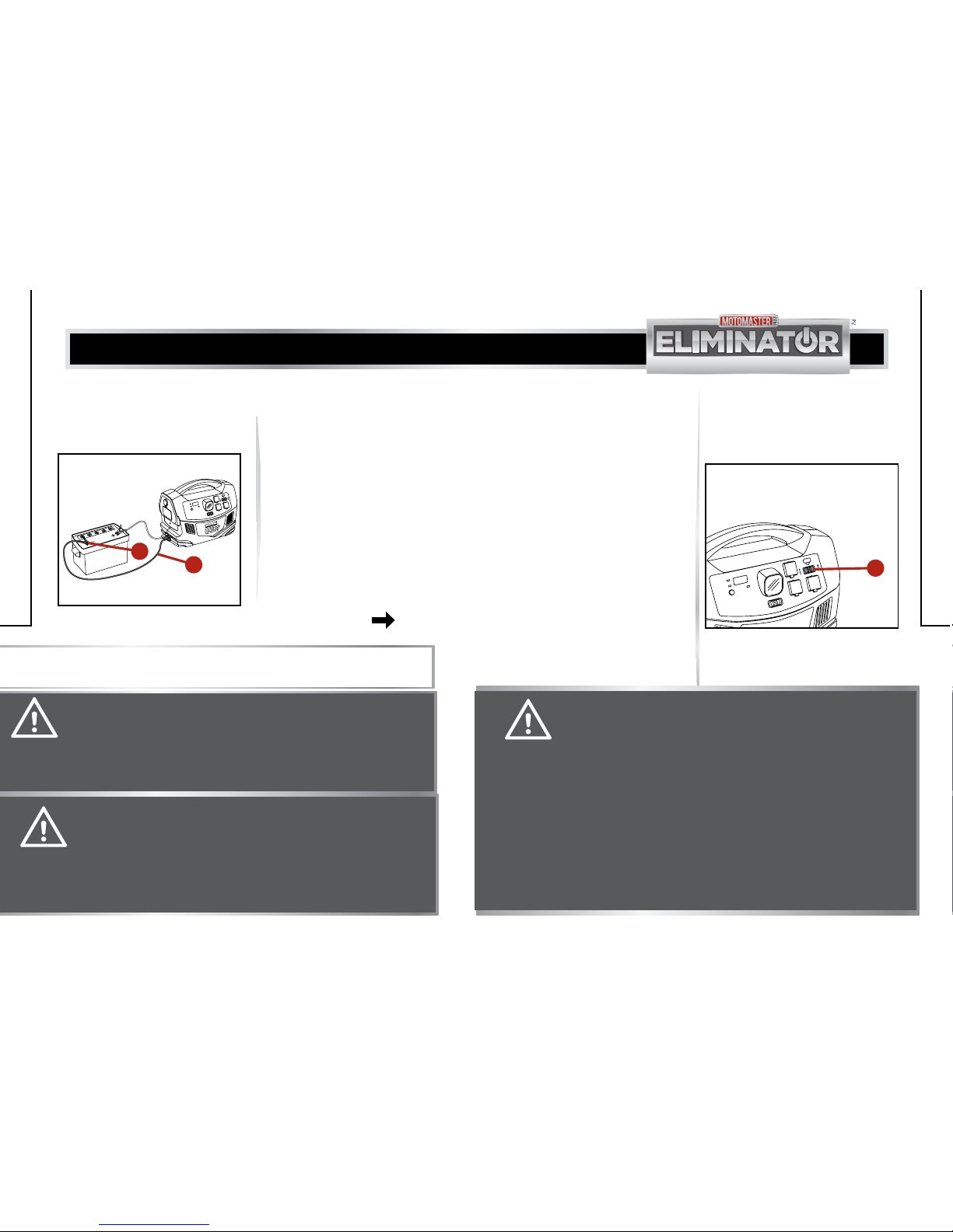
• Make sure to connect only to a 12 V external battery. A higher or lower
voltage battery will damage the power pack.
2. Connect the positive (red)
clamp (1) of the boosting cable to
the positive (+) terminal (2) of the
external battery (fig I).
28
model no. 011-2014-0 | contact us 1-877-619-6321
OPERATION
29
MAINTENANCE
4. Disconnect the cable
clamps from the battery and
replace the 250 A fuse if the
connections are reversed and
repeat the steps 1 and 2.
5. After use, remove the positive
(red) clamp and then the
negative (black) from the
external battery.
6. Store the boosting cables
separately after use.
7. Recharge the power pack
immediately after use. Refer
to Recharging the power pack
with AC charger pages
29-30.
3. Connect the negative (black)
clamp (1) of the boosting cable
to the negative (-) terminal (2)
of the external battery (fig J).
MM-112014-10
fig J
Charging status
Ètat de la charge
Digital Display Button
Bouton ďachage
numérique
Outout power Indicator
Voyant de la puissance
de sortie
Battery Capacity (%)
USB Port
011-2014-0
011-2014-0
600 W
Prise USB
LED Switch
FR. LED Switch
Adaptaeur
CA
AC
Adapter
AC/USB On Indicator
Voyant ďutilisation
de la prise USB/CA
USB On Indicator
OFF/ARRÊT
Voyant ďutilisation
de la prise USB
Capacité de la
batterie (%)
12 V DC
SOCKET
8. 8. 8
1
2
NOTE:
The 250 A fuse will be blown if the boosting cables are connected in reverse.
WARNING! CHEMICAL HAZARD
• Use only a sealed battery when the power pack is used indoors.
• Do not use automobile and marine batteries, as they emit fumes which are
undesirable for indoor use. Also, their acids are hazardous if spilled.
• Wear eye protection and protective clothing when connecting the power
pack to an external battery.
OPERATION
CAUTION! EQUIPMENT DAMAGE
• Make sure the cable clamps are connected correctly to the battery
terminals. A reversed polarity connection (positive to negative) may cause
sparks and break 250A fuse.
• Never allow the positive (red) and negative (black) clamps of the boosting
cables to touch each other or another common metal conductor. Doing so
may damage the equipment and create spark.
1. Turn OFF the AC/USB switch (1)
of the power pack (fig K).
RECHARGING THE POWER PACK
All rechargeable batteries gradually
discharge when left idle. Due to
inherent self discharge, lead acid
batteries must be charged once
every 90 days, especially in a warm
environment. Use the AC charger for
charging the battery.
RECHARGING THE POWER PACK
WITH AC CHARGER
MM-112014-11
fig K
Charging status
Ètat de la charge
Digital Display Button
Bouton ďachage
numérique
Outout power Indicator
Voyant de la puissance
de sortie
Battery Capacity (%)
011-2014-0
600 W
LED Switch
FR. LED Switch
AC/USB On Indicator
Voyant ďutilisation
de la prise USB/CA
USB On Indicator
OFF/ARRÊT
Voyant ďutilisation
de la prise USB
Capacité de la
batterie (%)
8. 8. 8
USB Port
011-2014-0
Prise USB
1
CAUTION! EQUIPMENT DAMAGE
• Always ensure that the internal battery is fully charged. Do not overcharge
the battery.
• Leaving a battery in a discharged state or without recharging every 90
days may result in permanent damage to the battery and poor boosting
performance.
NOTE: Press digital display button to check the battery status.
• Do not operate AC or DC appliances while the power pack is being charged.
Doing so may damage the AC charger.
• Do not attempt to recharge the internal battery if it is frozen.
• Use only the supplied AC charger or approved battery chargers to recharge
the internal battery, to ensure safe recharging and maximum battery life.
• Recharge the internal battery periodically to maintain maximum battery
capacity.

30
31
model no. 011-2014-0 | contact us 1-877-619-6321
OPERATION
TROUBLESHOOTING
NOTE:
• The charging status indicator will flash green while charging and glows green when
charging is completed.
• Do not unplug the power cord until the battery is fully charged. It may take 24 hours
or more to fully recharge the power pack battery provided the voltage is 115 V AC. If
the voltage is less than 115 V AC, it may take 24-48 hours to recharge.
• Once fully charged, the charging current automatically reduces to a floating charge
mode. In case of power interruption, the charging process automatically recovers
when power resumes.
OPERATION
2. Plug one end of 115 V AC
charger (1) into charging input
port (2) of the power pack and
other end to 115 V AC electrical
socket (3) (fig L).
MM-112014-12
fig L
Charging status
Ètat de la charge
Digital Display Button
Bouton ďachage
numérique
Outout power Indicator
Voyant de la puissance
de sortie
Battery Capacity (%)
USB Port
011-2014-0
011-2014-0
600 W
Prise USB
LED Switch
FR. LED Switch
Adaptaeur
CA
AC
Adapter
AC/USB On Indicator
Voyant ďutilisation
de la prise USB/CA
USB On Indicator
OFF/ARRÊT
Voyant ďutilisation
de la prise USB
Capacité de la
batterie (%)
12 V DC
SOCKET
8.8. 8
2
1
3
The power pack can also be
recharged using the DC charging
cable from a 12 V accessory outlet
of a vehicle only during emergency
situations.
1. Open the plastic cover of the
12 V DC outlet. Insert one plug
of the DC charging cable into the
12 V DC outlet.
RECHARGING THE POWER PACK
WITH DC CHARGING CABLE
2. Insert the other plug of the DC
charging cable into 12 V DC
accessory socket in vehicle..
3. Disconnect the DC charging cable
form the power pack and the
vehicle once the power pack is
fully charged or when the vehicle’s
engine is no longer running.
WARNING! EXPLOSION AND FIRE HAZARD
Do not use this DC charging cable, if vehicles electrical system operates
above 15 V. This condition is typically found in marine appliances or portable
generators with a DC output. Failure to comply may lead to accumulation of
hydrogen, causing fire or explosion hazard.
NOTE:
• The charging status LED indicator will not illuminate when the power pack is
recharged using the DC charging cable. This charging method is applicable only
during emergency purposes.
• The battery capacity shown in the digital display of the power pack is accurate
only when the power pack has been disconnected from all appliances and all
charging sources for at least 15 minutes.
CAUTION! EQUIPMENT DAMAGE
• Do not operate AC or DC appliances while the power pack is being recharged
with the DC charging cable.
• It is recommended to remove the DC charging cable from the power pack
and vehicle immediately if the battery is fully charged or vehicle engine is
turned OFF.
• Do not leave the power pack permanently connected to 12 V accessory
socket of the vehicle purposes.
• The charging status LED indicator will not illuminate when the Power Pack
is recharged using the DC charging. This charging method is applicable only
during emergency.
• The battery capacity shown in the digital display of the power pack is
accurate only when the power pack has been disconnected from all
appliances and all charging sources for at least 15 minutes.
32
33
model no. 011-2014-0 | contact us 1-877-619-6321
TECHNICAL SPECIFICATION
The power pack can be recharged
using a generator in three different
ways:
• Connect the AC charger between
the power pack and the
generator.
NOTE: This method requires extended
running time of the generator.
• Connect the power pack to an
auxiliary regulated 12 V DC
output of the generator.
NOTE: This method is to be adopted
for faster recharging.
• Connect the power pack to a
regulated 12 V DC lighter socket
of a generator. Refer to Recharging
the power pack with DC charging
cable pages 30-31.
RECHARGING THE POWER PACK
WITH REGULATED 12 V DC OUTLET
OF A GENERATOR
WARNING! EXPLOSION AND FIRE HAZARD
The generator output must be 15 V or less to charge the power pack. An
unregulated output or output exceeding 15 V DC may damage the battery and
lead to accumulation of hydrogen, thereby causing fire or explosion hazard.
OPERATION
NOTE:
Familiarize with the operating instructions of the generator before connecting the
generator to the power pack.
MAINTENANCE
The power pack will operate properly when maintained properly.
• Clean the exterior surface of the power pack with a damp cloth to
prevent accumulation of dust and dirt.
• Make sure the plastic covers on the 12 V DC outlet and AC outlet are
closed after use.
• Recharge the battery atleast once every 90 days. This will extend the
durability and efficiency of the battery.
MAINTENANCE
34
35
model no. 011-2014-0 | contact us 1-877-619-6321
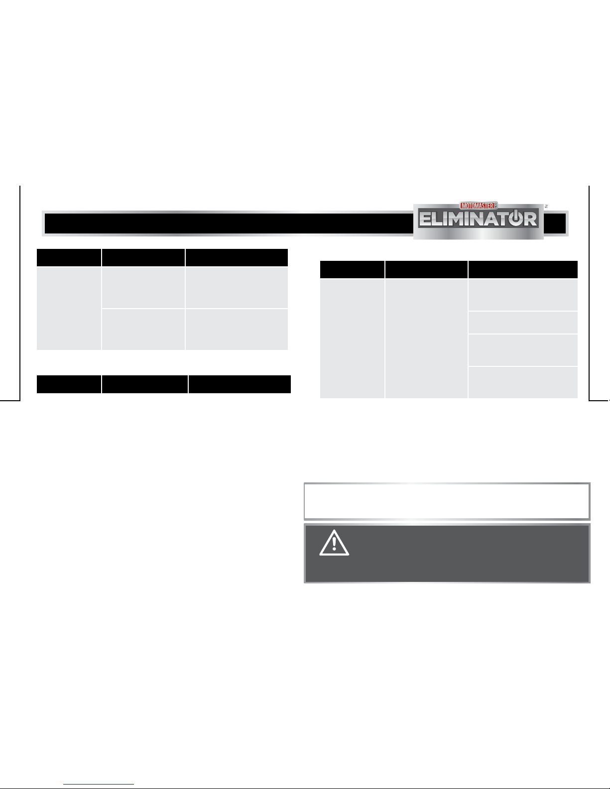
PROBLEM POSSIBLE CAUSE SOLUTION
The power pack cannot
jump start vehicle.
• The battery in the
power pack is not
fully charged.
• Recharge the battery.
Refer to Recharging the
power pack with AC
charger pages
29-30.
• The engine start
capacity exceeds the
power pack
jump-start capacity.
• Use a high capacity
power pack.
• The battery of the
power pack is
damaged.
• Replace the power pack’s
battery.
• Battery of the vehicle
is damaged.
• Replace the vehicle
battery.
The charging
status LED indicator does
not glow.
• There is no AC power
at the AC wall outlet.
• Ensure power is available
at the AC wall outlet.
• The AC charger does
not function.
• Replace the 115 V AC
charger.
The AC appliance does
not operate. The audible
alarm beeps.
• The battery has
discharged to less
than 11 V.
• Recharge the battery.
• The power pack is
overheated due to
poor ventilation or
excessively warm
environmental condi-
tions.
• Allow the power pack
to cool for 15 minutes
or more. Clear blocked
fan opening or remove
objects covering the unit,
then restart the power
pack. Move to a cool
environment.
TROUBLESHOOTING
TROUBLESHOOTING
PROBLEM POSSIBLE CAUSE SOLUTION
The charging
status LED indicator
flashes green but the
battery has not been
charged after 50
hours of charging.
• The output of the AC
charger is low.
• Replace the 115 V AC charger.
• The internal battery is
permanently damaged.
• Check the battery at a car
maintenance workshop.
• False LED reading. • Disconnect AC charger for 15
minutes. Check battery status.
Reconnect AC charger to a
different AC outlet.
• Switches are in the
“ON” position or a DC or
AC load is connected.
• Place all switches in “OFF”
position and disconnect all DC
or AC loads.
The AC appliance
does not operate.
The audible alarm
does not beep.
• The overload protection
feature trips, as the AC
appliance is rated more
than 600 W.
• Use AC appliance with a power
rating of less than 600 W.
• The high starting surge
current of the AC
appliance trips the
overload protection
feature, even if the AC
appliance is rated less
than 600 W.
• Use an AC appliance with a
starting surge current rated
within the power pack surge
capability. Refer to Technical
specification page 38.
TROUBLESHOOTING
36
37
model no. 011-2014-0 | contact us 1-877-619-6321
PROBLEM POSSIBLE CAUSE SOLUTION
The audio systems
and radios produce a
buzzing sound when
powered by the
power pack.
The power supply in audio
system does not adequately
filter the modified sine wave
generated by the power
pack.
Use sound system with high
quality filter.
BUZZING IN AUDIO SYSTEMS AND RADIOS
TROUBLESHOOTING
TROUBLESHOOTING
PROBLEM POSSIBLE CAUSE SOLUTION
The run time for
appliance is less
than operating limit.
• The internal battery is
not fully charged.
• Recharge the power pack
using the AC charger until the
charging status LED indicator
glows green.
• The power consumption
of the AC appliance is
higher than operating
limit.
• Check the power or wattage
rating of the AC appliance
(or current draw for 12 V DC
appliances).
PROBLEM POSSIBLE CAUSE SOLUTION
Lines scroll across
the TV screen.
The power pack operation
affects the TV signal
reception.
• Increase the distance between
the power pack and the TV,
antenna and cables.
• Adjust the orientation of power
pack, TV, antenna and cables.
• Increase the TV signal strength
by using a better antenna and a
shielded antenna cable.
• Try a different model. The models
may vary considerable in their
susceptibility to interference.
TELEVISION INTERFERENCE
WARNING!
• Do not disassemble the power pack, as it does not contain user-serviceable
parts.
• Have the power pack serviced by a qualified technician. Attempting to service
the power pack by yourself could result in electric shock or burn.
NOTE:
If the above solutions do not eliminate the problem, contact 1-877-619-6321 for
assistance between 9:00am to 5:00pm PST, Monday through Friday.

38
39
model no. 011-2014-0 | contact us 1-877-619-6321
ELECTRICAL SPECIFICATION
12 V DC SECTION
Internal battery (capacity/type) 28 Ah/12 V sealed lead-acid battery
DC power socket (maximum
continuous load)
12 A with automatic reset
Built-in LED light 0.3 W bulb
Fuse 250 A
AC POWER SECTION
Continuous output power 480 W
AC output power (5 minute) 600 W
AC output surge capacity 1000 W
AC output voltage 104 - 125 V AC
AC Output frequency 59 - 61 Hz
AC Output waveform Modified sine wave
No load current draw < 0.5 A
Input voltage range 11- 15 V DC
Low battery alarm 11 ± 0.3 V DC
Low battery shutdown 10.5 V ± 0.3 V DC
High battery voltage shutdown 15.5 V ± 0.5 V DC
Ambient operating temperature
range
32°F - 104°F (0°C - 40°C)
Storage temperature range 32°F - 86°F (0°C - 30°C)
INTERNAL BATTERY CHARGING CONTROLLER SYSTEM
AC charging bulk charging current 1000 mA
Peak charging voltage (nominal) 14.2 ± 0.2 V
Charging restart voltage (nominal) 12.9 ± 0.2 V
ACCESSORIES
Jump start cables (size / length) 19 mm2/0.8 m
AC to DC charging cable 1.8 m
DC to DC charging cable 0.9 m
PHYSICAL SPECIFICATION
Dimension (L x W x H) 14 19/32 x 9 8/16 x 11 12/16 "
(37.1 x 24.1 x 29.8 cm)
Weight 28 lb 13 oz (13.1 kg)
AC CHARGER SPECIFICATION
Input voltage 115 V AC
Output voltage 13.5 V DC
Input current 1 A
IMPORTANT:
All specifications are subject to change without notice. Please note that the
battery capacity has been tested in 20 hours mode.
TECHNICAL SPECIFICATION
TECHNICAL SPECIFICATION
Table of contents
Other Eliminator Inverter manuals


Popular Inverter manuals by other brands


Growatt
Growatt MIC 1000TL-X Installation & operation manual

Omnik
Omnik Omniksol-2k-TL3-S user manual

Philips
Philips Bodine ELI Series Installation and operating instructions

Mase
Mase IS 3.5 B installation manual

Siemens
Siemens MICROMASTER 440 Series operating instructions

Parkside
Parkside Starterset 300 W Smart instructions

kinetic
kinetic K-RACK installation guide

Huawei
Huawei SUN2000-6KTL-L1 quick guide

Gen Set
Gen Set MG 8000 I-H Use and maintenance manual

Sungrow
Sungrow SG36KTL-M Quick installation quide

Fimer
Fimer MEGASTATION Installation, operation and maintenance manual

Xantrex
Xantrex XPower Inverter 3000 installation guide