Elisa Emilie User manual

Emilie™and Rosa™
Installation, User and Care Guide
Emilie™und Rosa™
Installations-, Gebrauchs- und Pflegeanleitung
Emilie™et Rosa™
Guide d’installation, d’utilisation et d’entretien
Emilie™i Rosa™
Instrukcja instalacji, obsługi i pielęgnacji
Emilie™& Rosa™
Handleiding voor installatie, gebruik enonderhoud
UK
DE
FR
PL
NL

2 | ElisaTM EmilieTM and RosaTM Installation Guide
UK Installation Stages
Thank you for choosing an ElisaTM product to enhance your bathroom design.
This booklet provides information for Stages 2 and 3, please refer to the separate
installation guides for Stage 1 and outlet accessories.
The outlet accessories guides will provide helpful information so you can plan the
pipe runs and terminate in the required fittings/connectors.
Installation and user guides are packed with all of our products and for your
convenience they are also available by visiting www.aqualisainternational.co.uk
The installation of this product is a 3 stage process:
Stage 2
Fitting the valve
assembly
Stage 3
Fitting the compression
plate and fascia
Stage 1
Fitting the AquahubTM
and preparation for
outlet accessories
This guide covers the installation
of Stages 2 and 3

ElisaTM EmilieTM and RosaTM Installation Guide | 3
UK
Contents
Important Information
This product must be installed by a competent person in
accordance with the relevant Water Supply Regulations. Prior
to installation, ensure all literature supplied with this product is
read and understood. We have taken great care to ensure that
this product reaches you in perfect condition, however, should
any parts be damaged or missing please contact your point of
purchase. If you require assistance, please contact the Customer
Helpline. The AquahubTM is supplied with universal fixings intended
to secure it to a suitable surface.
4
5
6
6
7
8
9
10
11
12
13
13
14
15
16
17
18
21
22
23
Water supply requirements
Installation requirements
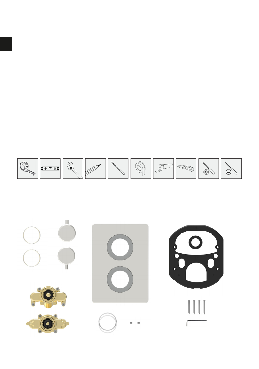
Tools required
Components RosaTM
Components EmileTM
Preparation
Fitting the thermostatic valve assembly
Fitting the headworks (Push button)
Commissioning the headworks and fitting the cover plate (Push button models)
Fitting the control dial (Push button models)
Changing cover buttons (Dual outlet (push button) models only)
Fitting the headworks (Dial models)
Commissioning and fitting the cover plate (Dial models)
Fitting the control dials (Dial models)
Commissioning – in service testing
Cartridge temperature adjustment
Troubleshooting
Caring for your shower
Maintenance
User instructions

4 | ElisaTM EmilieTM and RosaTM Installation Guide
UK Water supply requirements
This product has been designed and tested to comply with BS EN1287:1999 (LP-S)
and BS EN 1111:1999 (HP-S) Thermostatic Mixing Valves Standards.
Valves operating outside of the below conditions of use cannot be guaranteed as
type 2 valves.
Hot Water Maximum: 65˚C Cold Water Minimum: 10˚C
Recommended 60-65˚C Recommended 10-15˚C
Always maintain a 10˚C difference between hot system temperature and maximum
hot setting of valve.
Operating Pressure Range: Min. 1.0 bar, Max. 5 bar
When water pressure is higher than 5 bar a pressure reducing valve (not supplied)
must be fitted before the mixer. A setting of 3 bar is recommended.
This valve is suitable for gravity boosted, balanced high pressure and combination
boiler systems.
For gravity pumped systems use 22mm supply pipes and reduce to 15mm to
protrude through the finished wall.
Pump Installation:
PUMPS MUST NOT BE FITTED DIRECTLY TO A WATER MAIN.
REFER TO PUMP MANUFACTURERS INSTALLATION GUIDELINES.
Ensure there is adequate flow through the pump to activate the flow switches.
Combination boiler:
MUST have a minimum rating of 24kW (80,000 Btu) and be of the type fitted with
a fully modulating gas valve.
Boiler performance may affect outlet temperature.
Operating pressures:
Hot and cold supplies should be kept as even as possible in order to ensure the
maximum efficiency of the mixer.

ElisaTM EmilieTM and RosaTM Installation Guide | 5
UK
Installation requirements
Conditions of use for Type 2 (Thermostatic mixer) valves
High Pressure Low Pressure
Maximum Static
Pressure – Bar
10 10
Flow Pressure, Hot &
Cold - Bar
0.5 to 5 0.1 to 1
Hot Supply
Temperature - °C
55 to 65 55 to 65
Cold Supply
Temperature - °C
Equal to or
Less than 25
Equal to or
less than 25
Note: Valves operating outside these conditions cannot be guaranteed by the
Scheme to operate as Type 2 valves.
If a water supply is fed by gravity, then the supply pressure should be verified to
ensure the conditions of use are appropriate for the valve.
Recommended Outlet temperatures
The BuildCert TMV scheme recommends the following set maximum mixed water
outlet temperatures for use in all premises is 41°C for showers.
The mixed water temperatures must never exceed 46°C.
The maximum mixed water temperature can be 2°C above the recommended
maximum set outlet temperatures.
Note: 46ºC is the maximum mixed water temperature from the bath tap. The
maximum temperature takes account of the allowable temperature tolerances
inherent in thermostatic mixing valves and temperature losses in metal baths.
Warning: It is not a safe bathing temperature for adults or children.
The British Burns Association recommends 37 to 37.5ºC as a comfortable bathing
temperature for children. In premises covered by the Care Standards Act 2000, the
maximum mixed water outlet temperature is 43ºC.
6 | ElisaTM EmilieTM and RosaTM Installation Guide
UK
Tools required
Components - RosaTM
Installation requirements
The thermostatic mixing valve (TMV) will be installed in such a position that
maintenance of the TMV and its valves and the commissioning and testing of the
TMV can be undertaken.
The fitting of isolation valves is required as close as is practical to the water supply
inlets of the thermostatic mixing valve. Filtered inlet washers are supplied with
the product, if not used then the fitting of strainers is recommended as close as is
practicable to the water supply inlets of the thermostatic mixing valve.

ElisaTM EmilieTM and RosaTM Installation Guide | 7
UK
Components - EmilieTM Dual Outlet
Components - EmilieTM Triple Outlet

8 | ElisaTM EmilieTM and RosaTM Installation Guide
UK
Blank headworks
70-80mm depth
60-70mm depth
Preparation
1. Once all stage 1 leak and pressure
tests have been carried out; before
proceeding with the following
instructions, ensure that the built-in
servicing valves are in the closed
position (screwed down).
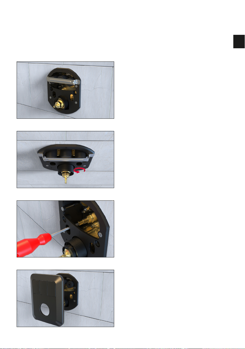
2. Remove the pressure testing plates
by unscrewing the bolts with the
long allen key provided.
Ensure all O’rings are installed
and within the grooves of the
valve assembly.
For push button models. Screw
the black extension caps onto the
headworks. (Use the shorter ones
for 60-70mm installation depths
OR the longer ones for 70-80mm
installation depths.)

ElisaTM EmilieTM and RosaTM Installation Guide | 9
UK
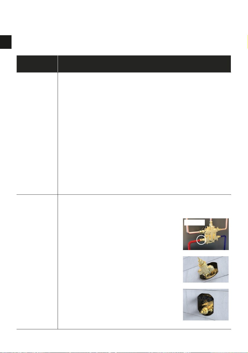
Fitting the thermostatic valve assembly
Offer the thermostatic assembly up to
the AquahubTM body and secure into
place using the long allen key provided
and the bolts.
Tighten all bolts incrementally in a
clockwise manner until tight.
(All models)
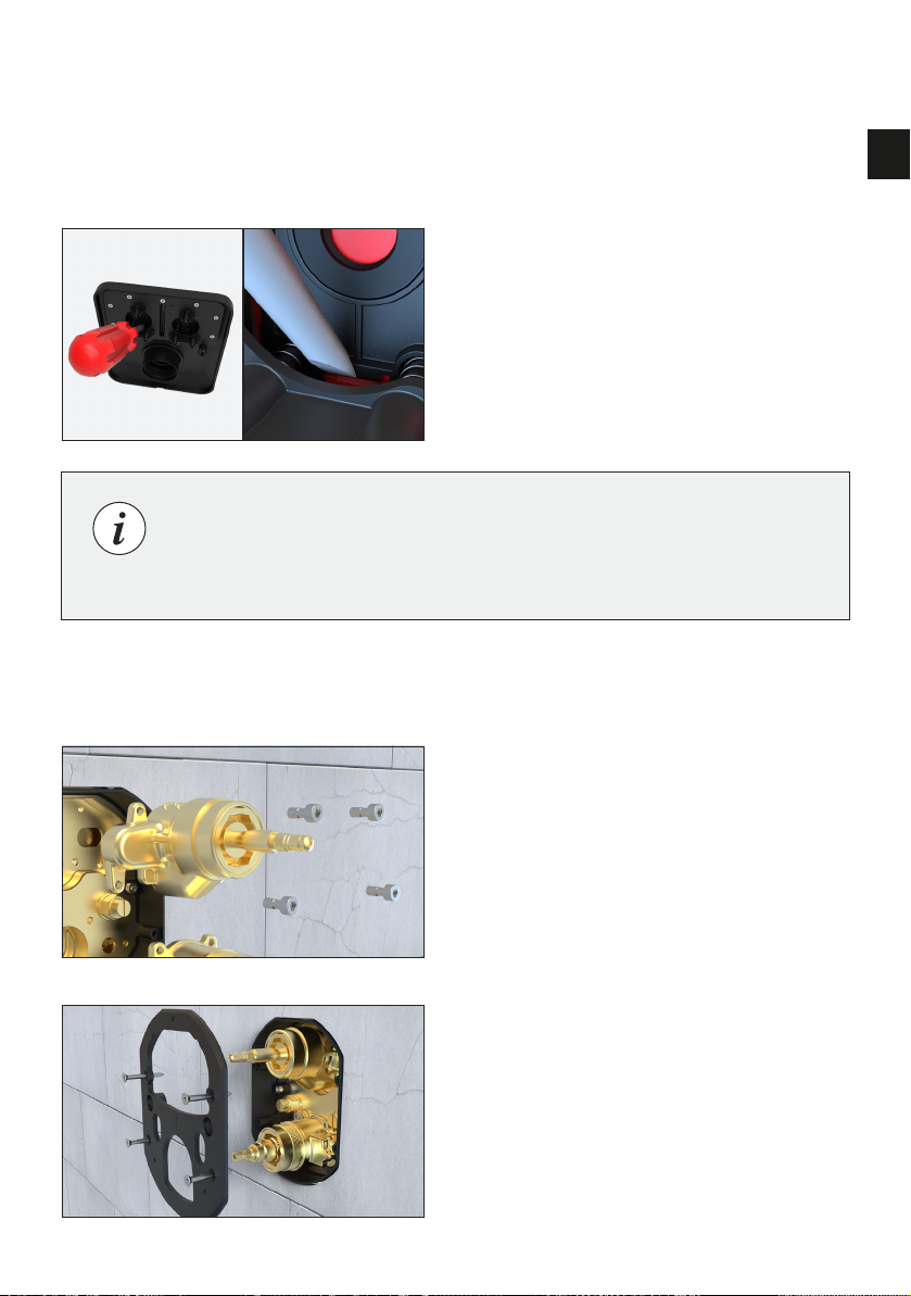
This can be easily corrected by
installing the assembly upside-down
(so the ‘H’ and ‘C’ is on the bottom)
- as shown.
Ensure ‘H’ (as circled)
is on the hot water inlet
side (normally left-hand
side as viewed from
the front).
If the water supplies
are reversed or have
been plumbed incorrectly,
the shower will not blend
the water correctly as
the supplies do not
correspond with
the inlets of the
thermostatic assembly.

10 | ElisaTM EmilieTM and RosaTM Installation Guide
UK Fitting the headworks (Push button)
1. Offer the headworks up to the
AquahubTM body and secure into
place using the long allen key
provided and the bolts.
Tighten all bolts incrementally in
a clockwise manner until tight.
2. Install the dial shroud by rotating it
onto the threaded headwork.
3. Install the compression plate using
the screws provided.
ElisaTM EmilieTM and RosaTM Installation Guide | 11
UK
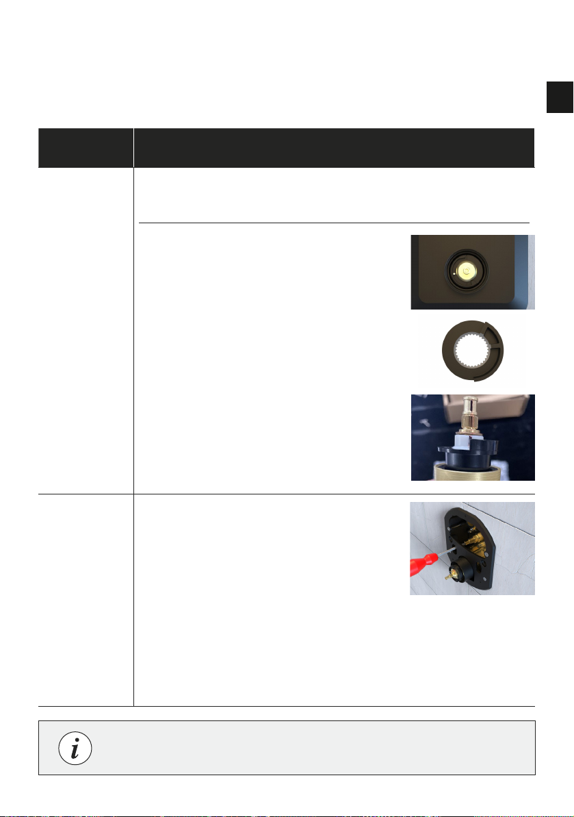
Commissioning the headworks
and fitting the cover plate (Push button models)
2. Unscrew the buttons until they touch
the bracket. Ensure all buttons are
level and remove the bracket.
3. Open both built-in servicing valves
(unwind – counter clock-wise).
4. Press the cover plate into position.
1. Ensuring the buttons are not
depressed, (in their fully extended
position) place the button
adjustment bracket on top.

12 | ElisaTM EmilieTM and RosaTM Installation Guide
UK
5. Fit the white spacer ring and flow
control dial before placing the
temperature override cam onto the
shaft. Ensuring it is in the correct
orientation(vertical – as shown).
7. Using the small allen key provided,
tighten the grub screw to secure the
dial, then press in the silicone cap.
Open the water isolation valves
and test.
Note: Silicone can be applied
around the wall plate apart from the
drainage hole at the bottom. This
must be left uncovered.
6. Place the second white spacer and
the temperature dial onto the shaft,
with the pin vertically aligned.
Fitting the control dial (Push button models)
ElisaTM EmilieTM and RosaTM Installation Guide | 13
UK
1. Offer the on/off headworks up
to the AquahubTM body and secure
into place using the long allen
key provided and the bolts.
Tighten all bolts incrementally in
a clockwise manner until tight.
2. Install the compression plate
using the screws provided.
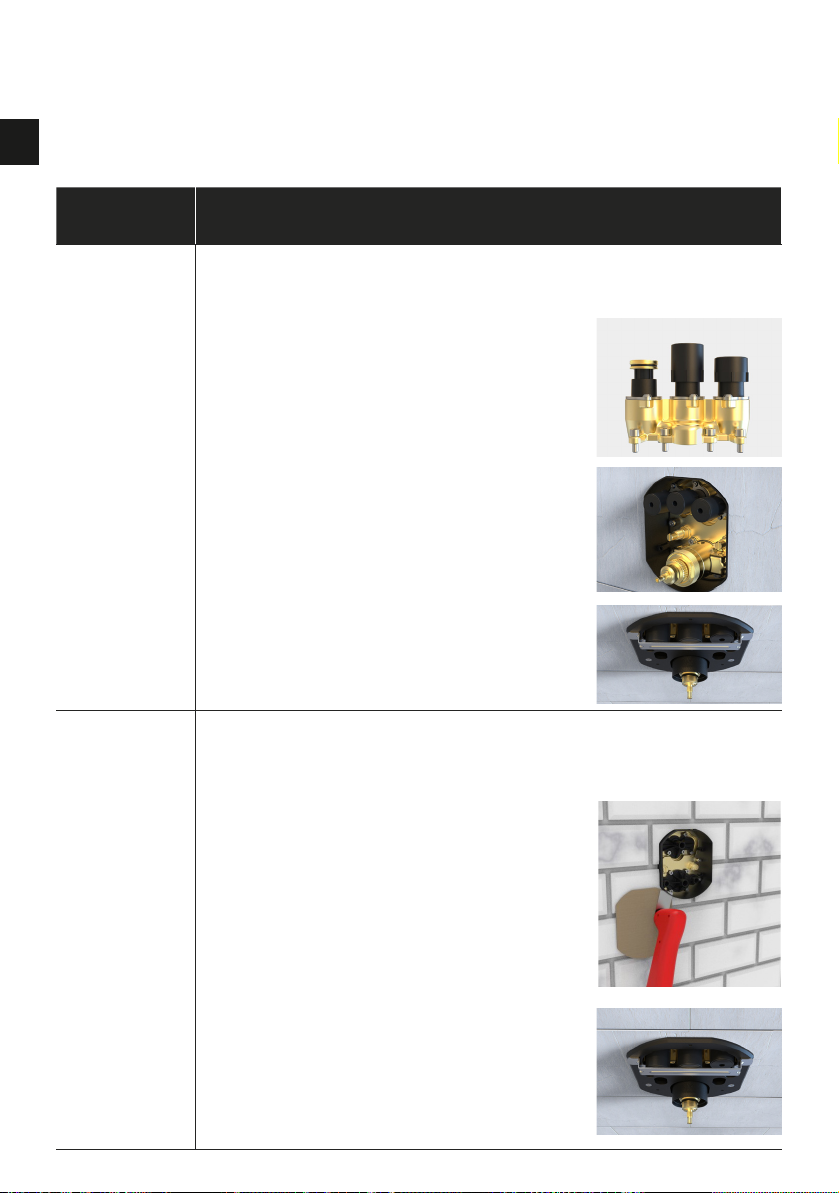
Changing cover buttons (Dual outlet (push button) models only)
Fitting the headworks (Dial models)
The buttons can be swapped to
correlate to your specific outlets if
they do not match. At the rear of the
cover, use a flat bladed screwdriver
to pry off the buttons then press the
new ones in place. (Press against
the areas highlighted in red in the
picture opposite)
Note: Spare alternative buttons are available should the outlets
be plumbed incorrectly, according to the button graphics.
Please contact customer services.

14 | ElisaTM EmilieTM and RosaTM Installation Guide
UK
4. Open both built-in servicing valves
(unwind – counter clock-wise).
5. Press the cover plate into position.
6. Fit the temperature override cam
onto the large spline ensuring
that it is in the correct orientation
(as shown).
3. Install the dial shrouds by rotating
them onto the threaded headworks.
Commissioning and fitting the cover plate (Dial models)

ElisaTM EmilieTM and RosaTM Installation Guide | 15
UK
8. Using the allen key supplied,
tighten the grub screw to secure
the control dial.
9. Insert the silicone cover cap, then
open the water isolation valves
and test.
7. Fit the white spacer rings
and control dials.
Override button needs to be
pressed in when fitting the
temperature control knob/dial.
Fitting the control dials (Dial models)
Note: Silicone can be applied
around the wall plate apart from the
drainage hole at the bottom. This
must be left uncovered.

16 | ElisaTM EmilieTM and RosaTM Installation Guide
UK
1. The designation of the thermostatic mixing valve matches the application.
2. The supply pressures are within the valves operating range.
3. The supply temperatures are within the valves operating range.
4. Isolating valves and strainers (filtered washers) are fitted.
If all these conditions are met, proceed to set the temperature as stipulated in the
Cartridge Temperature Adjustment section.
The mixed water temperature at the terminal fitting must never exceed 46ºC.
It is a requirement that all TMV2 approved valves shall be verified against the
original set temperature results once a year.
When commissioning / testing is due the following performance checks
shall be carried out:
• Measure the mixed water temperature at the outlet.
• Carry out the cold water supply isolation test by isolating the cold water supply
to the TMV, wait for five seconds, if the water is still flowing check that the
temperature is below 46ºC.
If there is no significant change to the set outlet temperature (+/-)2ºC or less
change from the original setting) and the fail – safe shut off is functioning, then the
valve is working correctly and no further service work is required.
Note: If there is a residual flow during the commissioning or the annual verification
(cold water supply isolation test), then this is acceptable providing the temperature
of the water seeping from the valve is no more than 2ºC above the designated
maximum mixed water outlet temperature setting of the valve.
Temperature readings should be taken at the normal flow rate after allowing for
the system to stabilise.
The first step in commissioning and in service testing of a thermostatic mixing
valve is to check the following:
Commissioning – in service testing

ElisaTM EmilieTM and RosaTM Installation Guide | 17
UK
The sensing part of the thermometer probe must be fully submerged in the water
that is to be tested.
Any TMV that has been adjusted or serviced must be re-commissioned and re-
tested in accordance with the instructions in the setting section.
The installation of thermostatic mixing valves must comply with the requirements of
the Water Supply (Water Fittings) Regulations 1999.
• N.B. Where water supplies vary significantly from the stated requirements
and /or the valve is not commissioned as instructed this product can reach
temperatures in excess of 50°C.
Cartridge temperature adjustment
18 | ElisaTM EmilieTM and RosaTM Installation Guide
UK
Problem Solution
Water
Leaks
If the AquahubTM or headworks have been incorrectly installed,
leaks could occur down or within the wall.
*Turn off the mains water supply*
Fully close the built in service valves, make sure the servicing valves are
tightened securely into the aquahubTM.
Check all inlets and outlets have been fitted with ptfe tape.
Check all headwork O’Rings are installed correctly and not perished.
Check blanking plugs have been applied to the correct/un-used outlets
Check the thermostatic cartridge and diverter
cartridge/valves are secure.
Check outlet plumbing.
Perform pressure and leak testing - refer to AquahubTM installation
guide (stage 1 installation).
Water is
only fully
hot OR fully
cold
If the inlets have been plumbed in incorrectly, the shower will only
dispense fully hot OR fully cold water. Despite turning the temperature
dial, the water will not blend to a showering temperature.
You have probably plumbed the water
supplies into the wrong inlets.
This can be easily corrected by installing
the headworks upside-down (so the ‘H’
and ‘C’ are on the bottom) see page 9.
Now the inlets have been switched and
your thermostatic cartridge should work
correctly.
Troubleshooting
Incorrect
ElisaTM EmilieTM and RosaTM Installation Guide | 19
UK
Troubleshooting
Dial
not fully
rotating
Remember to depress the pin in order to allow full rotation and
achieve temperatures over 38 degrees.
If depressing the pin is not helping,
its possible you have installed the
temperature override cam incorrectly
(see page 12 or 14).
Or your dial may not be aligned with
the cartridge. In this case, make sure the
markings on the teeth are aligned and
then place your dial on so the pin
is vertical.
Shower is
not working
You may have forgotten to open the
service valves within the aquahub /on the
incoming pipework or left your stop cock
(mains water supply valve) closed.
Remove the faceplate and fully loosen the
isolation valves. (The valves will unscrew
and protrude out when loosened). see
page 11 or 14.
If this has not solved the issue, check your
mains supply valve and external isolation
valves on your incoming pipework.
Problem Solution
Contact customer services for information on replacement parts.
20 | ElisaTM EmilieTM and RosaTM Installation Guide
UK
Problem Solution
Buttons not
working
If the wrong extension bosses have been screwed on, the buttons will
not fully depress or disengage the valves behind.
Remove the faceplate and
compression plate.
Unscrew the black extension bosses and
replace with the longer spare set.
(see page 8).
Readjust them to the correct depth using
the metal bracket. (see page 11).
Faceplate
not sitting
flush with
the wall
You may have incorrectly installed the AquahubTM shroud, button
extension bosses or compression plate, which will prevent the
faceplate from sitting flush with the wall.
Check the compression plate is sitting flush
with the tiles. If not, remove it and check the
plastic shroud behind has been trimmed
flush to the wall ( It should not protrude
more than 2-3mm past the finished wall
surface). If the shroud seems ok, make sure
the compression plate is located on the
shroud correctly and is screwed down tight
against the wall.
Lastly, if this has not corrected the problem,
it is likely that you have installed the wrong
button extension bosses. Unscrew them
and replace with the shorter set. Then
readjust using the metal bracket supplied.
(see page 11).
Troubleshooting
Blank headworks
70-80mm depth
60-70mm depth
This manual suits for next models
1
Table of contents
Languages:
Other Elisa Bathroom Fixture manuals


Popular Bathroom Fixture manuals by other brands

Kohler
Kohler Mira Sport Max J03G Installation and user guide

Moen
Moen 186117 Series installation guide

Hans Grohe
Hans Grohe Raindance Showerpipe 27235000 Instructions for use/assembly instructions

Signature Hardware
Signature Hardware ROUND SWIVEL BODY SPRAY 948942 Install

fine fixtures
fine fixtures AC3TH installation manual

LIXIL
LIXIL HP50 Series quick start guide


