Elite TXL200 5S User manual


FULLY ILLUSTRATED INSTRUCTION MANUAL
INCLUDING PARTS LIST
UK Office US Office
Elite Racing Transmissions UK Elite Racing Transmissions US
Gear Works 8444 Capricorn Way No. 10
Salem Street San Diego
Etruria California 92126
Stoke-on-Trent USA
ST1 5PR
www.eliteracingtransmissios.com www.elitetransmissions.com
Tel +44 1782 280136 Tel +1 (858) 220 0927
Fax +44 1782 269913 Fax As Above
Email [email protected]
Table of Contents
Technical Specifications Actuator Assembly
Diagram Parts List Instructions
General Notes Bearing Carrier Assembly
Diagram Parts List Instructions
Pinion Setting Section Gearbox Case Assembly
Diagram Parts List
Differential Preload Section Free Differential Assembly
Diagram Parts List Instructions
CWP Backlash Section LSD Differential Assembly
Diagram Parts List Instructions
Sequential Barrel Section Cam & Pawl Differential Assembly
Diagram Parts List Instructions
ALL PARTS, INFORMATION AND ILLUSTRATIONS CONTAINED WITHIN THIS PUBLICATION ARE COPYRIGHT OF ELITE
DESIGN & MANUFACTURING LTD., GEAR WORKS, SALEM STREET, ETRURIA, STOKE-ON-TRENT, ST1 5PR.
COPIES OF THE MANUAL CANNOT BE PRODUCED OR DISTRIBUTED WITHOUT THE WRITTEN PERMISSION OF ELITE
DESIGN & MANUFACTURING LTD.

TECHNICAL SPECIFICATIONS
TXL-200 5S
The TXL200-5S is a transaxle gearbox design for use in single seat / mid engine rear wheel
drive race cars. The gearbox has 5 forward gears and 1 reverse gear which are selected by
the use of a sequential mechanism.
The gear pattern is:
5/R . R . N . 1 . 2 . 3 . 4 . 5
The 5/R position is only used to aid the tightening of the pinion shaft and layshaft nuts. This
position must NOT be used whist the gearbox is in operation as it will cause a catastrophic
failure.
The drive from the power plant is transmitted to the gearbox layshaft via a custom input
shaft (varied to application). This is then transmitted via gears to the pinion shaft and into
the differential. Various differentials are available for the TXL200-5S including LSD, Cam
and Pawl and Free Diff.
Gear change is carried out through the actuator assembly to the sequential drum which then
moves a dog ring to engage each gear in turn in the above sequence. Reverse uses a sliding
gear to select in replacement of the dog ring system.
When coming down the gearbox a manually operated lock-out exists to stop the gearbox
hitting neutral and spiking the engine.
The gearbox case is manufactured from high grade cast aluminum. All gears in the gearbox
are manufactured from case hardening high grade material.
Lubrication in the gearbox is achieved by a simple splash system and retained within the
gearbox using oil seals
FOR ANY GUIDANCE OR QUESTIONS CALL US ON 01782 280136
The TXL200-5S gearbox is designed to be a fully stressed integral component within the
vehicles chassis with points provided for mounting of rear suspension.
Maximum Gearbox Operating Torque 200 lbs/ft
(This is application dependant; advice is
available by contacting Elite)
Gearbox Oil Type Fully synthetic gear oil
(Millers 75W90 is recommended)
Oil Quantity 1.5ltrs normal road tracks & 1.75ltrs oval tracks
(Capacity to filler on gearbox = 1.75litres)
CWP Backlash Setting 0.10 / 0.15 mm
Gearbox Dry Weight 36kg (including input shaft)

TORQUE SETTINGS
TXL-200 5S
Find below the torque settings for nuts and bolts:
Pinion Nut 150-180 LBS.FT
Layshaft Nut 150-180 LBS.FT
Crownwheel Bolts 80 LBS.FT
Pinion Bearing Nut 180 LBS.FT
Pinion Bearing Bolts 25 LBS.FT
Bearing Carrier Nuts 25 LBS.FT
Sideplate Nuts 25 LBS.FT
CAUTION: OVERTIGHTENING OF THE NUTS AND BOLTS MAY LEAD TO DAMAGE WITHIN THE GEARBOX

GENERAL NOTES
TXL-200 5S
All instructions and illustrations within this manual are created to
aid successful gearbox management. These should be read
carefully and adhered to in all instances to avoid damage to the
gearbox
›Before youdismantle the gearbox, ensure you have a clean tray available to place
parts.
›Before thegearbox is reassembled ensure all the parts which are to be reassembled
are fully cleaned and inspected for any problems such as excessive wear or fractures. Any
part which is thought to be damaged must be replaced with new components. If advice is
required on part please Contact Elite.
›Use onlygenuine Elite Racing Transmissions Parts in the TXL200-5S. Use of any parts
supplied by a third party cannot be guaranteed to be of the quality expected by the
customer of parts which are manufactured by Elite Racing Transmissions.
›Ensure allLocknuts, O’Rings and oil seals are replaced each time the gearbox is fully
stripped and rebuilt.
›The pinionand layshaft nut Torque Settings are to be checked on a regular basis. A
recommended checking interval of the above is prior to each race meeting or test day. All
other torque settings need to be checked every three race meetings/test days. This is
good practice as the wear within the gearbox can be monitored on a regular basis.
›On reassemblyof bearing in the gearbox lubricate with a small amount of oil. Never
run the gearbox after reassembly without doing this as the bearings will run dry until the
oil is circulated and cause damage which will reduce the life.
›Fill theoil to the desired level outline in the Technical Specifications section using a
measuring jug. Never overfill the gearbox as this will cause damage by the components
overheating and power loss within the transmission.
›Wear on the fork pins must be carefully monitored. Elite recommend changing fork
pins once least once a season. Failure of the fork pins causes a catastrophic failure of
the gearbox.

PINION SETTING
TXL-200 5S
Crownwheel and Pinions are supplied by Elite Racing Transmissions in matched sets and
these are identified by the numbers etched onto each set.
To make set-up simpler there is a pinion setting jig available from Elite Racing
Transmissions, Part Number ERT-TO-01.
TO FIT A NEW CROWNWHEEL AND PINION PROCEED AS FOLLOWS:-
›Press the pinion bearing onto the shaft; it is always advisable to fit a new pinion bearing
with a new pinion.
›Screw the pinion bearing nut onto the pinion shaft and tighten to between150-180lbs.ft.
There are special tools available from Elite to simplify this task; these are part numbers
ERT-TO-02 and ERT-TO-03.
›Select a shim and fit over the bearing, the old shim is a good starting point.
›Warm up the maincase to approximately 115°C and slide in the shaft, bearing and shims
from the differential side of the maincase. Secure the assembly into the maincase using
the Pinion Bearing Retaining Ring (ERT-IN-011), the washer (ERT-IN-012) and six bolts
(ERT-ST-010).
›When the maincase has cooled down fit the pinion setting jig onto the sideplate studs
and secure with four nuts.
›Using feeler gauges measure the gap between the jig and the ground end of the pinion
shaft.
›Establish the change of shim required to set the pinion at the correct depth and warm up
the case. Remove the pinion shaft and repeat steps 4 to 6 until the pinion shaft is in the
correct position.
›Following final assembly ensure that the six pinion bearing bolts are tightened to 25
lbs.ft.

DIFFERENTIAL PRELOAD SETTING
TXL-200 5S
Following the Pinion Setting to the correct height the next operation is to set the Differential
bearing preload. Special Dummy Bearing outer cones are available from Elite to Speed up
this operation, Part Number ERT-TO-004.
FOLLOW PROCEDURE BELOW TO SET THE DIFFERENTIAL BEARING PRELOAD
›Fit the assembled Differential unit to the gearbox followed by the left hand sideplate
assembly. Bolt the sideplate securely to the maincase.
›To measure the bearing pre-load, slowly undo the sideplate nuts. Using feeler gauges
measure the gap between the maincase and the sideplate. When there is no longer any
load on the sideplate nuts there is no preload on the differential bearings. To change the
preload, change the preload shims between the outer bearing cones and the sideplate.
The proper preload is set when the gap between the maincase and sideplate is 0.15 to
0.20mm.
›Next the CWP Backlash must be set. Do not yet replace the dummy bearing cones with
the correct parts.

CWP BACKLASH SETTING
TXL-200 5S
Following setting the Differential Preload Setting it is necessary to set the correct backlash
for the Crownwheel and Pinion.
FOLLOW PROCEDURE BELOW TO SET THE CWP BACKLASH
›Fit the differential to the gearbox and fit the left hand sideplate, fasten securely ensuring
that the differential is free to turn whilst tightening the nuts.
›When all of the nuts are fastened fit the front hub and the two rearmost hubs to the
pinion shaft, fit a spacer, ERT-TO-005, to the shaft and tighten up the pinion shaft nut to
approx. 15lb/ft.
›It is now possible to fit a Dial Test Indicator (DTI) to the rearmost maincase studs and fit
the pointer onto the rear most hub spline. By rotating the pinion shaft gently by hand the
backlash can be measured.
›The amount of backlash required is 0.1 to 0.15mm, if this has been achieved then
further adjustments need not be made, otherwise continue.
›Adjustment is made to the backlash by moving the diff preload shims from one sideplate
to the other, at this point no shims should be added or removed or this will alter the
Differential Preload. To increase the backlash shims should be moved from the left to the
right and vice versa to decrease the backlash.
›Measurements should be taken at various positions around the pinion shaft to average
out the effects of any manufacturing tolerances.
›If you still have the dummy bearing cones fitted replace them now with correct parts and
install the differential and sideplate.

SEQUENTIAL BARREL SETTING
TXL-200 5S
Fork setting on the EVD sequential transaxle is achieved by means of one shim on the
Selector Barrel.
TO DETERMINE THE THICKNESS FOR THIS SHIM PROCEED AS FOLLOWS
›Assemble front & middle hubs onto the pinion shaft and stand gearbox upright on its
front face.
›Using a caliper/vernier and straight edge measure the distance from the rear face of the
gearbox to the top of the rearmost hub.
›Make a note of this height and add 25.7mm to it. Note this number down.
›Stand the bearing carrier on its back face with the barrel fitted to the bearing (with no
shim fitted). Measure from the bearing carrier front face to the bottom of the middle
neutral track position. Add 3.5mm to this figure.
›Subtract the track position size from the hub position figure. This size is the size of the
shim required.
›Fit this shim to the selector barrel and fit to the bearing carrier, tighten up the selector
barrel nut to 50lbs.ft.
›The selector forks can now be slid over the barrel and located with the fork pin (ERT-IN-
020) and circlip (ERT-ST-040).
IT MUST BE NOTED THAT IF THE FORK PIN CIRCLIP IS REMOVED ON
REFITTING THEN A NEW CIRCLIP MUST BE USED.
AFTER INSTALLATION ENSURE THAT CIRCLIP IS SAT PROPERLY IN GROOVE.
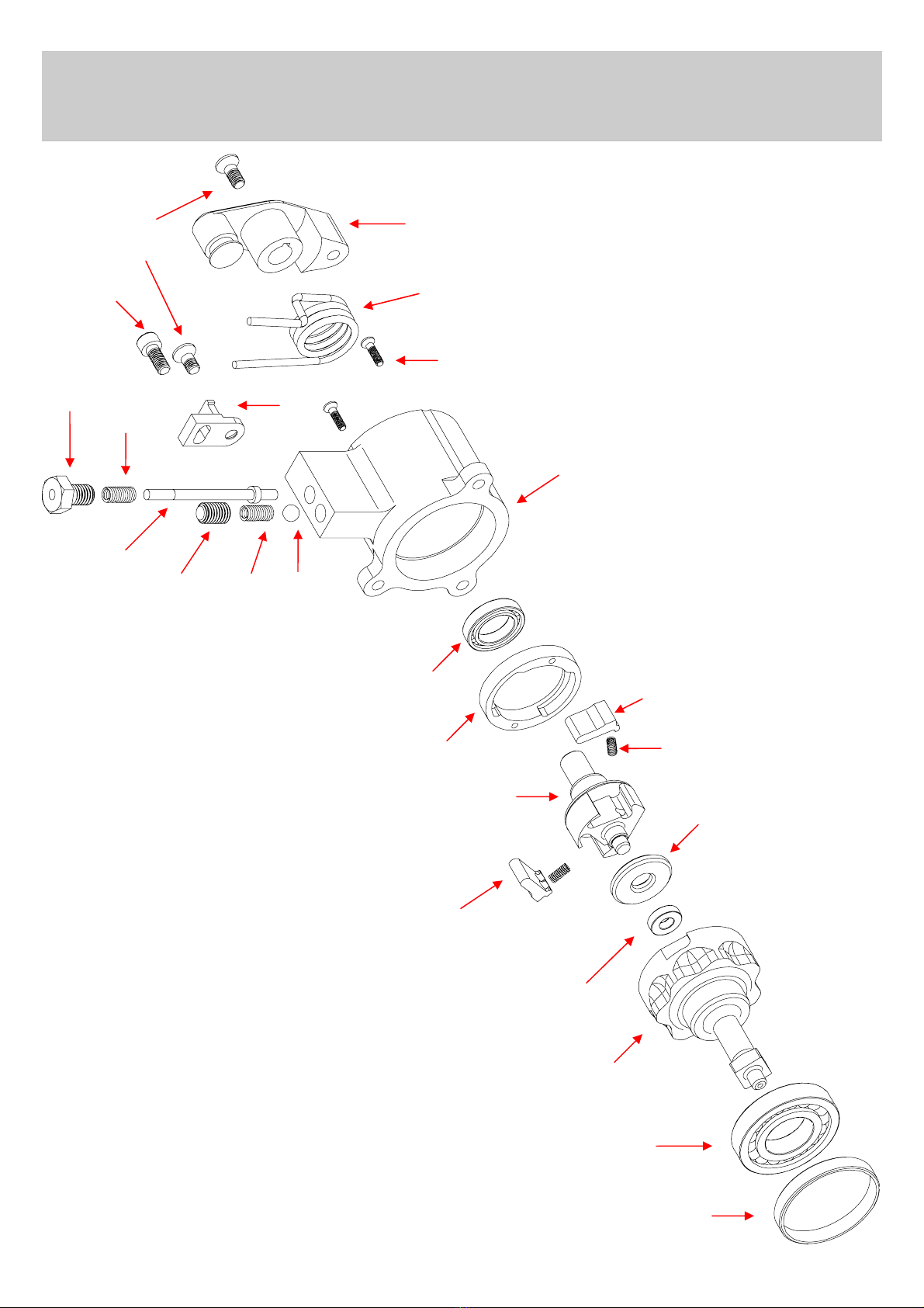
ACTUATOR ASSEMBLY
ERT90303
FIG 1
ACTUATOR ASSEMBLY
ERT90303
01
02
03 04
05
06
07
08
09
10 11
12
13 14 15
16
17
19
20
20
21
22
23 18
Table of contents
Popular Controllers manuals by other brands

Digiplex
Digiplex DGP-848 Programming guide

YASKAWA
YASKAWA SGM series user manual

Sinope
Sinope Calypso RM3500ZB installation guide

Isimet
Isimet DLA Series Style 2 Installation, Operations, Start-up and Maintenance Instructions

LSIS
LSIS sv-ip5a user manual

Rockwell Automation
Rockwell Automation 1769-L31 installation instructions


