Elitech STC-1000Pro TH User manual

Tsv Hsv
STC-1000Pro TH / STC-1000WiFi TH
Intelligent Temperature and Humidity Controller

1. Introduction
STC-1000Pro TH / STC-1000WiFi TH is an integrated plug-and-play
temperature and humidity controller. It has temperature and humidity
integrated probe and is pre-connected to two output sockets to control
temperature and humidity simultaneously.
The large LCD screen intuitively displays temperature, humidity, and other
parameters. With the three-key design, it enables quick parameter setting,
such as alarm limit, calibration, protection time, unit switching, etc.
It is mainly used in aquarium, pet breeding, incubation, seedling mat,
greenhouse, and other application scenarios.
2. Overview
Fig. 1
*UK/EU/ US Standards are available.
Power Plug*
Temperature &humidity sensor
Main controller
outlets *
Tsv Hsv
-1-

2.1 Display Introduction
Please check the instructions below before parameter configuration.
Fig. 2
Tsv Hsv
1 2 3 4 5 6 7
8
9
10
11
12
Wi-Fi connection status Not
connected
Non-
setting
Resetting
OFF
No alarm Alarm
Protection delay
Protection delay
Protection delay
Protection delay
ON
ON
OFF ON
OFF ON
OFF ON
Setting
Cooling status
Alarm status
Heating Status
Humidification status
Dehumidification status
Setting status
Temperature-present
value
Humidity-present value
Temperature-set value
Humidity-set value
Parameter code1
Status
OFF Flashing ON
S/N
1
2
3
4
5
6
7
8
9
10
11
12
Icon Function
1 Refer to 2.2 Parameter Table for details.
Table 1
-2-

2.2 Parameter Table
Fig. 3
Tsv Hsv
8
1
910 11 12 13 14 15 16
2 3 4 5 6 7 17
S/N Code Function Setting range Default value
Temperature related parameters
1TCH C / H
-5 ~ 70°C
23 -158°F
C
25
77
Temperature
cooling/heating
mode selection
Temperature set
value
TS2
0.2 ~ 15°C
1 ~ 30°F
2
3
Temperature
dierential
Temperature
protection time 0 ~ 10 Min 3
TD
TPT
3
-5 ~ 70°C
23 ~ 158°F
35
95
Temperature
alarm high limit
TAH5
-5 ~ 70°C
23 ~ 158°F
0
32
Temperature
alarm low limit
TAL6
-10 ~ 10°C
-15 ~ 15°F
0
0
Temperature
calibration
Temperature unit C / F C2
TCA
CF
7
8
4
-3-

S/N Code Function Setting range Default value
Humidity related parameters
9 HDH H / D
5 ~ 99%RH
H
50
1 ~ 30%RH 5
Dehumidifying/
Humidifying
mode selection
Humidity set valueHS10
Humidity
dierential
Humidity
protection time 0 ~ 10 Min 3
5 - 99%RH 99
5 - 99%RH 5
HD
HPT
11
Humidity alarm
high limit
HAH13
Humidity alarm
low limit
HAL14
-10 ~ 10%RH 0
Humidity
calibration
Continuous
operating time 0 ~ 999 Min 30
HCA
COT
15
16
Backlight time 0 ~ 999 Min 30BL17
12
Table 2
2The default temperature unit for US version is °F, while the
UK and European version is °C.
-4-

2.3 Button Operation
Incorrect operation may cause serious damage to you or your device.
Please make sure you read and understand the following procedures
before starting.
3. Operation
S/N Button Operating Non-setting
mode
Setting mode
Number
flashing
Number
non-flashing Remarks
Table 3
1
2
3
4
5
Press
Press Number
non-flashing
Non-setting mode
Number
flashing
View parameter
value
Previous
parameter Increases
Continuous
increases
Press and
hold
Press
Press and
hold
Press and
hold for
5 seconds
Press and
hold for
5 seconds
Press and
hold for 3
seconds
Setting mode
View parameter
value
Wi-Fi reset
Equipment
reset
Next
parameter Decreases
Continuous
decreases
Only for
STC-1000
WiFi TH
+
+
+
-5-

Plug the probe fully to the bottom of the main controller's headphone jack.
Otherwise, a buzzer alarm will be triggered, and the "Err" code will show on
the LCD after powering the controller.
Please insert the power plug into the power socket to power on the control-
ler (within the range of 100-240VAC).
The screen will light up and display the temperature, humidity, and other
readings.
3.1 Sensor Installation
3.2 Power-on
Fig. 4
Fully Plug In
Fig. 5
-6-

Press and hold button for 3 seconds to enter the parameter setting mode,
the buzzer will beep, and the LCD will display icon.
In the menu setting, press button and the Tsv3 parameter light will be on
or flashes. When it is flashing, press or button to switch to the next
parameter; when the parameter light is on, press or button to increase
or decrease the setting value.
In the menu setting, press and hold button for 3 seconds to save settings
and exit; or the controller will save and exit setting mode after 30 seconds of idle.
The Tsv displays temperature-related parameters and Hsv displays humidity-
related parameters.
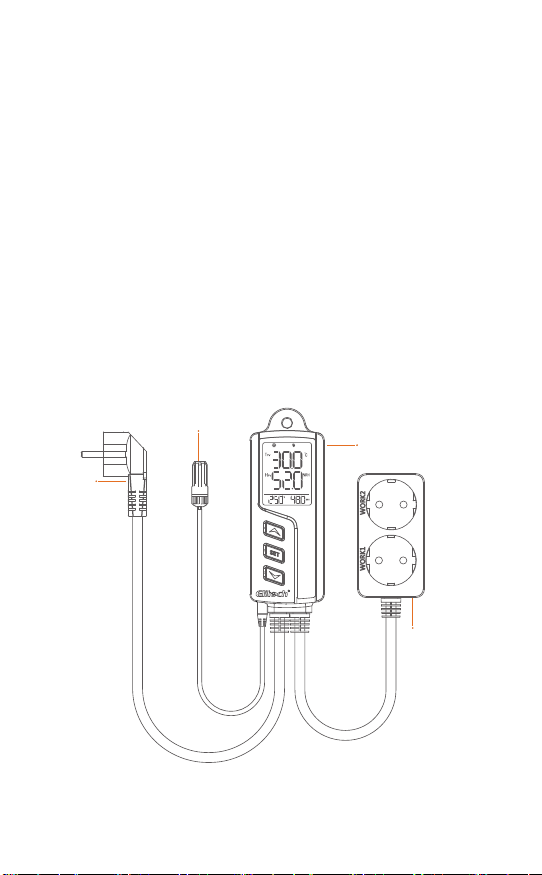
For example, set TS and TD parameters into TS = 20°C and TD = 5°C respec-
tively.as shown in Fig. 6.
① Press button and release after the buzzer beeps (about 3 seconds);
② Press button, and the parameter code will display TS;
③ Press button, and will flash, indicates TS parameter is ready
to be set;
④Press (or press and hold) button to change the value to 20;
⑤ Press button, and TPV will appear;
⑥ Press button, and the parameter code will display TD;
⑦ Press button, and TPV will flash,indicates TD parameter is ready
to be set;
⑧ Press (or press and hold) button to change the value to 5;
⑨Press button and release after the buzzer beeps (about 3 seconds)
to exit the parameter setting.
3.3 Parameter Setting
Note: Dotted-line in the figure shows the numbers are flashing (ready for
setting); solid-line shows the numbers stop flashing (value is set).
See the flow chart below to change other parameter values one by one.
as shown in Fig. 7.
-7-

Fig. 6
Fig. 7
press and hold
key 3s
Enter
Tsv Hsv Ts v Hsv
Temperature
set value
Temperature
mode selection
Tsv Hsv Ts v Hsv Ts v Hsv Ts v Hsv
Tsv Hsv
Tsv Hsv
Exit
Temperature
dierential
①
②
⑧
③
④
⑤
⑥
⑦
⑨press and hold
key 3s
Tsv Hsv Tsv Hsv Ts v Hsv Ts v Hsv
Hsv Hsv
Hsv
Temperature set valueTemperature mode selection Temperature calibration Temperature uint
Humidity set value Continuous working time Backlight timeHumidity mode selection
Hsv
press and hold
key 3s
Enter
-8-

Cooling mode (TCH = C)
When TPV (temperature-present value) is higher than TS + TD
(temperature-set value + temperature dierential), will appear,
work1 will be turned on, and cooling will begin;
When TPV (temperature-present
value) is lower than TS (temperature
-set value), will disappear, work1
will be turned o, and cooling will
stop.
For example: TS = 15°C, TD = 5°C, as
shown in Fig. 8.
4.1 Temperature Setting - TCH, TS, TD
4. Function Description
Heating mode (TCH = H)
When TPV (temperature-present value) is lower than TS - TD (tempera-
ture-set value - temperature dierential), will appear, work1 will be
turned on, and heating will begin;
When TPV (temperature - present
value) is higher than TS (temperature
-set value), will disappear, work1
will be turned o, and heating will
stop.
For example: TS = 15°C, TD = 5°C, as
shown in Fig. 9.
WORK1 is a temperature socket and the time interval from its power-o
to power-on again should meet the time requirement for TPT. If not, or
will flash.
This protection time requirement should also be satisfied when the
controller is just powered on.
4.2 Temperature Protection Time - TPT
t
°C
20
TS=15
TD=5
WORK1 On
WORK1 O
Fig. 8
TD=5
WORK1 On
WORK1 O
t
°C
10
TS=15
Fig. 9
-9-

When HPV (humidity-present value) is
lower than HS (humidity set value),
will disappear, work2 will be turned o,
and dehumidifying will stop.
For example: HS = 50% RH, HD = 10%
RH, as shown in Fig. 10.
When TPV (temperature-present value) is higher than TAH (temperature alarm
high limit), the temperature alarm high limit will be triggered and code will
be displayed;
When TPV (temperature-present value) is lower than TAL (temperature alarm
low limit), the temperature alarm low limit will be triggered and code will
be displayed;
During the alarm, the buzzer makes a sound of "bi-bi-Biii" until the temperature
is back to the normal temperature range; or press any button to mute the alarm.
During the temperature alarm limit, the output of WORK1 socket is not aected.
4.3 Temperature Alarm Limit- TAH, TAL
The temperature can be calibrated if the temperature-present value
deviates from the actual temperature.
TPV (temperature - present value after calibration) = TPV (temperature -
present value before calibration) + TCA (temperature calibrated value).
4.4 Temperature Calibration - TCA
The temperature unit can be switched between Celsius and Fahrenheit.
The temperature related parameter values will be restored to factory
default values after the temperature unit is changed.
4.5 Temperature Unit - CF
Dehumidifying mode (HDH = D)
When HPV (humidity-present value) is higher than HS + HD (humidity set
value + humidity dierential), will appear, work2 will be turned on, and
Dehumidifying will begin;
4.6 Humidity Settings - HDH, HS, HD
t
%RH
60
HS=50
HD=10
WORK2 On
WORK2 O
Fig. 10
-10-

WORK2 is a humidity socket and the time interval from its power-o to
power-on again should meet the time requirement for HPT. If not, or
light will flash.
This protection time requirement should also be satisfied when the
controller is just powered on.
4.7 Humidity Protection Delay - HPT
When HPV (humidity-present value) is higher than HAH (humidity alarm
high limit), the humidity alarm high limit will be triggered and code will
be displayed;
When HPV (humidity-present value) is lower than HAL (humidity alarm
lower limit), the humidity alarm lower limit will be triggered and code
will be displayed;
During the alarm, the buzzer makes a sound of "bi-bi-Biii" until the humid-
ity is back to the normal humidity range; or press any button to mute the
alarm. During the humidity alarm high limit, the output of WORK2 socket
is not aected.
4.8 Humidity Alarm High Limit - HAH, HAL
The humidity can be calibrated if the humidity-present value deviates from the
actual humidity.
HPV (humidity-present value after calibration) = HPV (humidity-present value
before calibration) + HCA (humidity calibrated value).
4.9 Humidity Calibration - HCA
When HPV (humidity-present value) is
higher than HS (humidity set value),
will appear, work2 will be turned o, and
humidifying will stop.
For example: HS = 50%RH, HD = 10%RH,
as shown in Fig. 11.
Humidifying Mode (TCH = H)
When HPV (humidity-present value) is lower than HS-HD (humidity set
value - humidity dierential), will appear, work2 will be turned on, and
Humidifying will begin;
HD=10
WORK2 On
WORK2 O
t
%RH
40
HS=50
Fig. 11
-11-

5. Equipment Installation
Fig. 12
During humidity control, when COT≠0 and output conditions are met, WORK2
socket will work in on-o-on-o.... mode. COT is time on as well as time o.
eg, if COT=10, the WORK2 output socket will turn on for 10 minutes and o for
10 minutes, then repeat.
When COT = 0 and output conditions are met, WORK2 output socket will not
be aected by COT.
4.10 Continuous Operating Time - COT
BL is the screen display time. When BL=0 indicates display is always on.
4.11 Backlight Time - BL
As a safety precaution, it is recommended to power on the equipment
after the installation is completed.
The only installation method is by hanging the equipment. Please check
the installation distance and screw size according to its application scenar-
io before installation.
The schematic diagram of equipment installation is shown below:
-12-

7. Restore Operation Function
8. Access to Network (for STC-1000WiFi TH)
6. Alarm
7.1 Restore Factory Settings
When the controller is powered on and in non-setting parameter status,
please press + + buttons simultaneously on the main controller
and release until the screen turns o automatically. Wait for the
equipment to restart automatically and restore to factory settings.
7.2 Restore Wi-Fi Network Settings (for STC-1000WiFi TH)
If you would like to reconfigure to a new Wi-Fi network, please keep the
equipment in power-on status, press + buttons and release when the
symbol on the screen flashes. The icon will disappear after the network
restoration is completed.
Please do not power o the equipment during the restoration process.
STC-1000WiFi TH features a built-in Wi-Fi module that allows you to
remotely view and configure it on the app.
In the following circumstances during operation, the buzzer will give a
"bi-bi-Biii" alarm, and at the same time, the alarm symbol on the screen
will appear. Press any button to mute the alarm.
S/N Code Function Socket output status
1
2
3
4
5
Sensor failure Outputs terminated
Outputs unchanged
Outputs unchanged
Outputs unchanged
Outputs unchanged
Temperature alarm high limit
Temperature alarm low limit
Humidity alarm high limit
Humidity alarm low limit
-13-

Fig. 13
Fig. 14
Fig. 15
8.1 Before you begin, please make sure:
STC-1000WIFI TH has embedded the Wi-Fi module that supports remote
viewing, configuartion and other operations via Elitech app.
● Download the latest “Elitech iCold” app from APP Store or Google Play,
register you free Elitech account and singn in.
● Connect your mobile phone to preferred Wi-Fi (2.4GHz Wi-Fi, 5GWi-Fi is
not compatible).
● Check the sticker on controller’s back, which should contain QR code and
20-digital GUID
8.2 Connect the device to Elitech iCold app
1. Find the QR code label on the device.
(It shows QR code and 20 numbers)
2. Power on the device.
3. Log in your Elitech account (Register
an Elitech account)
4. Click the sign + on top right and add
device.
5.Click the sign on top right / Scan the
QR code on the label,or manually
type in 20 GUID numbers.Enter the
device name that your prefer, and
click Add.
Enter Device Name or Model
No Device Found
Search
(GMT+00:00) Europe/London
-14-

Note: The device allows Wi-Fi to be congured within 30 minutes after
power on. After 30 minutes, it needs to be powered o for a restart. Or you
may refer to 7.2 Restore Wi-Fi Network Settings.
6.A window will pop up "The device
scanned is a Wi-Fi device. Would you
like to set Wi-Fi?"Click OK.
7. Enter Wi-Fi password, click OK, and
wait until the operation finishes.
The whole process takes about 10
seconds. It exits configuration interface
after the network is connected
successfully.
The main interface displays the device
is online.
Meanwhile, the sign shows on top
of the screen.
Fig. 16
Fig. 17
(GMT+00:00) Europe/London
-15-

9. Technical Parameters
Working voltage: 100~240VAC, 50/60Hz
Temperature measurement range: -5~70°C / 23~158°F
Temperature control range: -5~70°C / 23~158°F
Temperature measurement accuracy: ±0.5°C /±1°F
Temperature resolution: 0.1°C /0.1°F
Humidity measurement range: 5~99%RH
Humidity control range: 5~99%RH
Humidity measurement accuracy: ±5%RH
Humidity resolution: 0.1%RH
Relay contact output capacity: 10A (resistive) / 100 ~ 240VAC
Output power: 2200W (resistive) in total/
200W (inductive) per channel @220VAC,
1100W (resistive) in total/
100W (inductive) per channel @110VAC
Total power consumption: <5W
Working environment temperature: 0°C~60°C / 32~140°F
Storage temperature: -10°C~70°C / 14~140°F
Length of power probe: 1.5m
Length of output power probe: 0.3m
Enclosure size: 165 x 60 x 32 mm
Length of sensor cable: 2m (including probe length)
Best viewing angle of LCD screen: 6 O'clock direction
Wi-Fi type*: 2.4G (not support 5G)
*Only for STC-1000WiFi TH
-16-

V1.1
MADE IN CHINA
This manual suits for next models
1
Table of contents
Other Elitech Controllers manuals