manuals.online logo
Brands
  1. Home
  2. •
  3. Brands
  4. •
  5. IBM
  6. •
  7. Controllers
  8. •
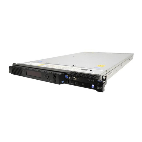
  9. IBM FlashSystem 900 Instruction Manual

IBM FlashSystem 900 Instruction Manual

3746 Nways Multiprotocol Controller
Models 900 and 950 ÉÂÔ
Multiaccess Enclosure
Installation and Maintenance
(Starting from EC F12720)
SY33-2124-02
3746 Nways Multiprotocol Controller
Models 900 and 950 ÉÂÔ
Multiaccess Enclosure
Installation and Maintenance
(Starting from EC F12720)
SY33-2124-02
Note!
Before using this information and the product it supports, be sure to read the general information under “Notices”
on page xv.
Third Edition (July 1999)
This edition applies to the multiaccess enclosure of the 3746 Nways multiprotocol Controller Models 900 and 950.
Order publications through your IBM representative or the IBM branch office serving your locality. Publications are not stocked at the
address given below.
A form for readers’ comments appears at the back of this publication. If the form has been removed, address your comments to:
Department CGFA
Design & Information Development
IBM Corporation
PO Box 12195
Research Triangle Park NC 27709
U.S.A.
When you send information to IBM, you grant IBM a nonexclusive right to use or distribute the information in any way it believes
appropriate without incurring any obligation to you.
 Copyright International Business Machines Corporation 1998, 1999. All rights reserved.
US Government Users Restricted Rights – Use, duplication or disclosure restricted by GSA ADP Schedule Contract with IBM Corp.
Contents
Figures . . . . . . . . . . . . . . . . . . . . . . . . . . . . . . . . . . . . . . . . . . xi
Notices . . . . . . . . . . . . . . . . . . . . . . . . . . . . . . . . . . . . . . . . . xv
Electronic Emission Notices .............................. xvi
Industry Canada Class A Emission Compliance Statement .......... xvi
Avis de conformité aux normes d'Industrie Canada .............. xvi
European Union (EU) Mark of Conformity Statement ............. xvi
Japanese Voluntary Control Council for Interference (VCCI) Statement ... xvii
Korean Communications Statement ....................... xvii
Taiwanese Class A Warning Statement .................... xviii
New Zealand Radiocommunications (Radio) Regulations .......... xviii
Notice to UK Users .................................. xviii
Year 2000 Statement ................................ xviii
Trademarks . . . . . . . . . . . . . . . . . . . . . . . . . . . . . . . . . . . . . . . xix
Product Safety Information ............................. xxi
General Safety . . . . . . . . . . . . . . . . . . . . . . . . . . . . . . . . . . . . . xxi
Safety Notices . . . . . . . . . . . . . . . . . . . . . . . . . . . . . . . . . . . . . xxi
Safety Notices for United Kingdom ........................ xxi
Service Inspection Procedures ............................ xxi
About this Book ................................... xxiii
Who Should Use this Book ............................. xxiii
How to Use this Book ................................ xxiii
How this Book is Organized ............................. xxiii
Where to Find More Information .......................... xxiv
World Wide Web ................................. xxiv
Online Documentation from CD-ROM ...................... xxv
Service Personnel Definitions ............................. xxv
Chapter 1. Installing and Setting Up Your MAE ................ 1-1
Overview . . . . . . . . . . . . . . . . . . . . . . . . . . . . . . . . . . . . . . . . 1-2
Installation Time . . . . . . . . . . . . . . . . . . . . . . . . . . . . . . . . . . . . 1-3
Multiaccess Enclosure Installation Tasks ...................... 1-3
Step 1 - Preparing Your Installation ......................... 1-4
Step 2 - Installing the MAE .............................. 1-5
Step 3.1 - Connecting the MAE to a 7585 .................... 1-11
Step 3.2 - Connecting the MAE to a 6275 .................... 1-12
Step 3.3 - Other MAE Cables Installation ..................... 1-13
Single ac Outlet Distribution Box ........................ 1-13
Dual ac Outlet Distribution Box ......................... 1-14
Step 4 - Installing the SIE Cassette in the 3746-9X0 .............. 1-15
Step 5 - Connecting the MAE to the 3746-9X0 .................. 1-16
Installing the 8228s .................................. 1-16
Connect the MAE to the 3746-9X0 thru 8228 ................. 1-18
Connect the MAE from the SAC to the SIE Cassette ............ 1-19
Step 6 - Customizing the MAE ........................... 1-21
Chapter 2. Maintaining the Code on the MAE ................. 2-1
Overview of Managing the MAE Code and Configuration Files ......... 2-2
 Copyright IBM Corp. 1998, 1999 iii
Displaying the Level of the MAE LIC ........................ 2-3
Installing a New Version of the LIC and Firmware ................. 2-5
Installing MCF on the MAE .............................. 2-6
Removing Microcode Fixes on the MAE ..................... 2-10
Displaying a MAE Configuration .......................... 2-12
Chapter 3. Multiaccess Enclosure Problem Determination ......... 3-1
Multiaccess Enclosure Power Supply ....................... 3-1
System Card LEDs ................................. 3-1
LED Indicators . . . . . . . . . . . . . . . . . . . . . . . . . . . . . . . . . . . . . 3-2
Power Supply Status ................................ 3-3
System Card Status ................................. 3-3
SAC Card Status .................................. 3-3
Adapter Card Status ................................ 3-3
Important Phone Numbers .............................. 3-4
Troubleshooting . . . . . . . . . . . . . . . . . . . . . . . . . . . . . . . . . . . . . 3-5
Diagnosing Hardware Problems .......................... 3-5
Diagnosing Operational Code and Configuration Problems .......... 3-5
Maintenance Actions and Procedures ...................... 3-5
MAP 0300: Multiaccess Enclosure Basic Verification ............. 3-6
MAP 0310: Parallel Channel Problem Isolation ............... 3-16
MAP 0320: Verifying Repair Action for Parallel Channel .......... 3-17
Preparing the Multiaccess Enclosure Hard Disk ............... 3-18
Adapter Wrap Plugs (Service Kit - Part Number 30L6123) ......... 3-20
LIC 282, LIC 290, and LIC 291 External Wraps ................ 3-21
External Wrap Testing Parallel Channel Adapters ................ 3-23
Concepts . . . . . . . . . . . . . . . . . . . . . . . . . . . . . . . . . . . . . . 3-23
Rules for Parallel Channel Adapter Testing .................. 3-23
Preparing the Wrap Blocks ............................ 3-24
Running the Parallel Channel Adapter External Wrap Tests ........ 3-27
Installing and Removing Channel Adapters .................... 3-33
Parallel Channel Attachment ........................... 3-33
V-Cables . . . . . . . . . . . . . . . . . . . . . . . . . . . . . . . . . . . . 3-37
Channel Interface Cables ........................... 3-37
Using Interconnected V-Cables ......................... 3-38
Installing Channel Feature 3299 ........................ 3-39
Parallel Channel Adapters Installation and Removal ............. 3-40
Installing Channel Adapters .......................... 3-40
Removing Channel Adapters ......................... 3-43
ESCON Channel Adapter Cable Installation .................. 3-44
Installing Optical Fiber Cables ........................ 3-44
Channel Interface Cable Replacement Procedure .............. 3-46
Removing a Channel Interface Cable .................... 3-46
Reinstalling the Channel Interface Cable .................. 3-46
Routing the Adapter Cables through the Cable Guides ........... 3-47
Releasing the Device to Your Customer .................... 3-47
Chapter 4. Multiaccess Enclosure FRU Exchange .............. 4-1
Prerequisite Before some FRU Exchanging .................... 4-2
Exchanging a Power Supply ............................. 4-4
Exchanging the System Card ............................. 4-5
Exchanging the SAC ................................. 4-24
Exchanging the Hard Drive on the System Card ................. 4-25
Exchanging the Memory on the System Card .................. 4-32
iv 3746-9X0: MAE Installation and Maintenance
Exchanging the PCMCIA Card ........................... 4-35
PCMCIA Speed Setting ............................. 4-36
PCMCIA Checking . . . . . . . . . . . . . . . . . . . . . . . . . . . . . . . . 4-37
Exchanging the Fan Tray .............................. 4-40
Exchanging an Adapter ............................... 4-42
Exchanging the ISDN Daughter Card ....................... 4-46
Exchanging the ESCON Adapter .......................... 4-48
Exchanging the Backplane ............................. 4-51
Chapter 5. Multiaccess Enclosure Firmware and Operational Code .... 5-1
Running Diagnostics . . . . . . . . . . . . . . . . . . . . . . . . . . . . . . . . . . 5-1
Using Multiaccess Enclosure Firmware ....................... 5-2
Attended Mode . . . . . . . . . . . . . . . . . . . . . . . . . . . . . . . . . . . . . 5-2
Unattended Mode . . . . . . . . . . . . . . . . . . . . . . . . . . . . . . . . . . . 5-2
Starting Firmware . . . . . . . . . . . . . . . . . . . . . . . . . . . . . . . . . . . . 5-3
Accessing the Firmware from the Service Processor .............. 5-3
The Function Keys ................................... 5-5
Obtaining Help . . . . . . . . . . . . . . . . . . . . . . . . . . . . . . . . . . . . . 5-5
Managing the Configuration .............................. 5-6
Selecting the Boot Sequence ............................. 5-7
Selecting a Device To Test .............................. 5-9
Using the Utilities ................................... 5-10
Setting the Power-On Password ........................ 5-11
Setting the Supervisory Password ....................... 5-12
Enabling Unattended Start Mode ........................ 5-13
Disabling Unattended Start Mode ........................ 5-14
Removing the Supervisory Password ...................... 5-15
Updating System Firmware ........................... 5-16
Displaying the Event / Error Log ........................ 5-23
Viewing or Setting Vital Product Data ..................... 5-24
Manipulating the Dead Man Timer ....................... 5-27
Setting Up Remote Initial Program Load .................... 5-28
Change Management . . . . . . . . . . . . . . . . . . . . . . . . . . . . . . . 5-29
Xmodem Software Selection ......................... 5-29
Restoring the Image Code of the Multiaccess Enclosure Hard Disk .... 5-30
Using Operational Diagnostics ........................... 5-41
Overview of Diagnostic Functions and Status Information .......... 5-41
Accessing the Operational Diagnostics from the Service Processor .... 5-42
Using the Command Line Interface Operational Diagnostics ........ 5-44
Testing the Adapters ................................. 5-49
Running Diagnostics on the New Adapter ................... 5-50
ESCON-only Tests . . . . . . . . . . . . . . . . . . . . . . . . . . . . . . . . . . 5-53
Run the Light Test on the New Fiber Optic Cable .............. 5-53
ESCON Interactive Test Options ........................ 5-56
ESCON Optical Power Measurement Test .................. 5-57
CE Leaving Procedure ................................ 5-60
Check List . . . . . . . . . . . . . . . . . . . . . . . . . . . . . . . . . . . . . 5-60
Chapter 6. Installing Options . . . . . . . . . . . . . . . . . . . . . . . . . . . 6-1
Installing a Dual Power Supply (FC 3500) ..................... 6-2
Machines Affected . . . . . . . . . . . . . . . . . . . . . . . . . . . . . . . . . . 6-2
Related BMs and ECs ............................... 6-2
BMs to be Installed ................................. 6-2
Preparation . . . . . . . . . . . . . . . . . . . . . . . . . . . . . . . . . . . . . . 6-2
Contents v
Programming . . . . . . . . . . . . . . . . . . . . . . . . . . . . . . . . . . . . . 6-2
Purpose and Description .............................. 6-2
Purpose . . . . . . . . . . . . . . . . . . . . . . . . . . . . . . . . . . . . . . 6-2
Description . . . . . . . . . . . . . . . . . . . . . . . . . . . . . . . . . . . . 6-2
Installation Time . . . . . . . . . . . . . . . . . . . . . . . . . . . . . . . . . . . 6-3
Tools/Materials Required . . . . . . . . . . . . . . . . . . . . . . . . . . . . . . 6-3
Safety . . . . . . . . . . . . . . . . . . . . . . . . . . . . . . . . . . . . . . . . . 6-4
Details of Installation ................................ 6-4
Test procedures. . . . . . . . . . . . . . . . . . . . . . . . . . . . . . . . . . . 6-5
Field Updating. . . . . . . . . . . . . . . . . . . . . . . . . . . . . . . . . . . . 6-5
Installing an Adapter (FC 32XX). ........................... 6-6
Machines Affected . . . . . . . . . . . . . . . . . . . . . . . . . . . . . . . . . . 6-6
Related BMs and ECs ............................... 6-6
BMs to be Installed ................................. 6-6
Preparation . . . . . . . . . . . . . . . . . . . . . . . . . . . . . . . . . . . . . . 6-6
Programming . . . . . . . . . . . . . . . . . . . . . . . . . . . . . . . . . . . . . 6-7
Purpose and Description .............................. 6-8
Purpose . . . . . . . . . . . . . . . . . . . . . . . . . . . . . . . . . . . . . . 6-8
Description . . . . . . . . . . . . . . . . . . . . . . . . . . . . . . . . . . . . 6-8
Installation Time . . . . . . . . . . . . . . . . . . . . . . . . . . . . . . . . . . . 6-8
Tools/Materials Required . . . . . . . . . . . . . . . . . . . . . . . . . . . . . . 6-8
Safety . . . . . . . . . . . . . . . . . . . . . . . . . . . . . . . . . . . . . . . . . 6-9
Details of Installation ................................ 6-9
Installing an Adapter ............................... 6-9
Configuring the Adapter. ........................... 6-10
Test procedures . . . . . . . . . . . . . . . . . . . . . . . . . . . . . . . . . . 6-16
Field Updating . . . . . . . . . . . . . . . . . . . . . . . . . . . . . . . . . . . 6-16
After Installation. . . . . . . . . . . . . . . . . . . . . . . . . . . . . . . . . . . . 6-17
Publications Update . . . . . . . . . . . . . . . . . . . . . . . . . . . . . . . . 6-17
Parts Disposition . . . . . . . . . . . . . . . . . . . . . . . . . . . . . . . . . 6-17
Machine Records . . . . . . . . . . . . . . . . . . . . . . . . . . . . . . . . . 6-17
Chapter 7. Removing or Relocating Your Multiaccess Enclosure ..... 7-1
Deleting the Configuration Parameters ....................... 7-2
Disconnecting the MAE from Power and Removing Cables ........... 7-3
Preparing the MAE for Shipment ........................... 7-3
Appendix A. Multiaccess Enclosure Components Location ........ A-1
Appendix B. MAE Adapters Plugging Rules ................. B-1
Assumptions . . . . . . . . . . . . . . . . . . . . . . . . . . . . . . . . . . . . . B-1
Plugging Sequences . . . . . . . . . . . . . . . . . . . . . . . . . . . . . . . . . B-1
Multiaccess Enclosure Slots and Adapters .................... B-2
Appendix C. Parameter Worksheets . . . . . . . . . . . . . . . . . . . . . . C-1
For the multiaccess enclosure ........................... C-1
LAN link from the MAE to the 3746 ........................ C-1
Appendix D. Controller Expansion Component Locations ........ D-1
Appendix E. Managing Operational Code and Configuration Files ... E-1
Reconfiguring . . . . . . . . . . . . . . . . . . . . . . . . . . . . . . . . . . . E-1
How Software Files Are Managed ......................... E-1
How to View the Files .............................. E-1
vi 3746-9X0: MAE Installation and Maintenance
How to Reset the Multiaccess Enclosure ................... E-2
Migrating to a New Code level ......................... E-2
Installing a New User Module .......................... E-3
Other Change Management Functions ..................... E-4
Describe Load Images ............................ E-4
Disable Dumping . . . . . . . . . . . . . . . . . . . . . . . . . . . . . . . . E-4
Enable Dumping . . . . . . . . . . . . . . . . . . . . . . . . . . . . . . . . E-4
Erase Files . . . . . . . . . . . . . . . . . . . . . . . . . . . . . . . . . . . E-4
Using the Copy Command ............................ E-5
Configuring the MAE via CCM ........................... E-6
Activate MAE Configuration Via CCM ....................... E-14
Appendix F. Common Tasks . . . . . . . . . . . . . . . . . . . . . . . . . . . . F-1
LED States / Adapter Status ............................ F-1
The Firmware Interface ............................... F-1
Command Line Interface .............................. F-1
Displaying List of Configured Interfaces ..................... F-1
Displaying the Operational State of the Interfaces ............... F-2
Verifying Connectivity . . . . . . . . . . . . . . . . . . . . . . . . . . . . . . . . F-2
Viewing Vital Software Data ............................ F-2
Viewing Vital Hardware Data ........................... F-3
Adding/Removing an Adapter Using CCM .................... F-3
Suspend Traffic on an Adapter Port ....................... F-3
Resume Traffic on an Adapter Port ........................ F-3
Up-to-Date multiaccess enclosure Information ................. F-4
Disabling Interfaces that Have WAN Reroute Enabled ............. F-4
Enabling WAN Reroute after You Have Disabled it ............... F-5
Spare Interfaces . . . . . . . . . . . . . . . . . . . . . . . . . . . . . . . . . . . F-5
Appendix G. Hardware Error Codes ...................... G-1
Appendix H. Parts Listing . . . . . . . . . . . . . . . . . . . . . . . . . . . . H-1
Assembly 1: Final Assembly, Multiaccess Enclosure ............ H-2
Appendix I. Multiaccess Enclosure Cables ................... I-1
Cables Between the Multiaccess Enclosure, 3746 Models 900/950 and
Service Processor (based on 6275) ....................... I-1
Cables Between the Multiaccess Enclosure, 3746 Models 900/950 and
Service Processor (based on 7585) ....................... I-2
Cable From the Multiaccess Enclosure Lan Adapter to the 8228 ....... I-3
Pin Assignment . . . . . . . . . . . . . . . . . . . . . . . . . . . . . . . . . . I-3
Cable from the Multiaccess Enclosure System Card PCMCIA Token-Ring
Adapter to Service Processor .......................... I-4
Interchange Circuits for the Cable between the Multiaccess Enclosure and
the Service Processor ............................. I-4
Balun . . . . . . . . . . . . . . . . . . . . . . . . . . . . . . . . . . . . . . . I-5
Balun Pin Assignment .............................. I-5
Cable from the Multiaccess Enclosure EIA-232 Connector to the Service
Processor . . . . . . . . . . . . . . . . . . . . . . . . . . . . . . . . . . . . . . I-6
Interchange Circuits for the Cable between the Multiaccess Enclosure and
the Service Processor ............................. I-6
Adapter Cable . . . . . . . . . . . . . . . . . . . . . . . . . . . . . . . . . . I-7
Cable From the Service Processor or Network Node Processor to the 8228 I-8
Pin Assignment . . . . . . . . . . . . . . . . . . . . . . . . . . . . . . . . . . I-8
Contents vii
Multiaccess Enclosure Unit Power Cables .................... I-9
Local Area Network Cable ........................... I-10
Cable Between the 3746 SIE Cassette and the MAE SAC Card ..... I-11
Interchange Circuit . . . . . . . . . . . . . . . . . . . . . . . . . . . . . . . I-11
Multiaccess Enclosure LIC Cables ......................... I-13
V.24 / EIA-232 Fanout Cable .......................... I-13
Interchange Circuits . . . . . . . . . . . . . . . . . . . . . . . . . . . . . . I-14
Cable List . . . . . . . . . . . . . . . . . . . . . . . . . . . . . . . . . . . . I-14
V.35 Fanout Cable ................................ I-15
Interchange Circuits . . . . . . . . . . . . . . . . . . . . . . . . . . . . . . I-16
Cable List . . . . . . . . . . . . . . . . . . . . . . . . . . . . . . . . . . . . I-16
V.36 Fanout Cable ................................ I-17
Interchange Circuits . . . . . . . . . . . . . . . . . . . . . . . . . . . . . . I-18
Cable List . . . . . . . . . . . . . . . . . . . . . . . . . . . . . . . . . . . . I-18
X.21 Fanout Cable ................................ I-19
Interchange Circuits . . . . . . . . . . . . . . . . . . . . . . . . . . . . . . I-20
Cable List . . . . . . . . . . . . . . . . . . . . . . . . . . . . . . . . . . . . I-20
V.24 / EIA-232 Serial Cable ........................... I-21
Interchange Circuits . . . . . . . . . . . . . . . . . . . . . . . . . . . . . . I-21
Cable List . . . . . . . . . . . . . . . . . . . . . . . . . . . . . . . . . . . . I-21
V.24 / EIA-232 Direct Attachment Cable .................... I-22
Interchange Circuits . . . . . . . . . . . . . . . . . . . . . . . . . . . . . . I-22
Cable List . . . . . . . . . . . . . . . . . . . . . . . . . . . . . . . . . . . . I-22
V.35 Serial Cable ................................. I-23
Interchange Circuits . . . . . . . . . . . . . . . . . . . . . . . . . . . . . . I-23
Cable List . . . . . . . . . . . . . . . . . . . . . . . . . . . . . . . . . . . . I-23
V.35 Direct Attachement Cable ......................... I-24
Interchange Circuits . . . . . . . . . . . . . . . . . . . . . . . . . . . . . . I-24
Cable List . . . . . . . . . . . . . . . . . . . . . . . . . . . . . . . . . . . . I-24
V.36 Serial Cable ................................. I-25
Interchange Circuits . . . . . . . . . . . . . . . . . . . . . . . . . . . . . . I-25
Cable List . . . . . . . . . . . . . . . . . . . . . . . . . . . . . . . . . . . . I-25
V.36 Direct Attachment Cable .......................... I-26
Interchange Circuits . . . . . . . . . . . . . . . . . . . . . . . . . . . . . . I-26
Cable List . . . . . . . . . . . . . . . . . . . . . . . . . . . . . . . . . . . . I-26
X.21 Serial Cable ................................. I-27
Interchange Circuits . . . . . . . . . . . . . . . . . . . . . . . . . . . . . . I-27
Cable List . . . . . . . . . . . . . . . . . . . . . . . . . . . . . . . . . . . . I-28
X.21 Direct Attachement Cable ......................... I-29
Interchange Circuits . . . . . . . . . . . . . . . . . . . . . . . . . . . . . . I-29
Cable List . . . . . . . . . . . . . . . . . . . . . . . . . . . . . . . . . . . . I-29
Multi-Purpose RJ-45 Cable ........................... I-30
Interchange Circuits . . . . . . . . . . . . . . . . . . . . . . . . . . . . . . I-30
Cable List . . . . . . . . . . . . . . . . . . . . . . . . . . . . . . . . . . . . I-30
RJ-48 T1 ISDN Pri Cable ............................ I-31
Interchange Circuits . . . . . . . . . . . . . . . . . . . . . . . . . . . . . . I-31
Cable List . . . . . . . . . . . . . . . . . . . . . . . . . . . . . . . . . . . . I-31
E1 ISDN Pri Cable ................................ I-32
Interchange Circuits . . . . . . . . . . . . . . . . . . . . . . . . . . . . . . I-32
Cable List . . . . . . . . . . . . . . . . . . . . . . . . . . . . . . . . . . . . I-32
RJ-45 J1 ISDN Pri Cable ............................. I-33
Interchange Circuits . . . . . . . . . . . . . . . . . . . . . . . . . . . . . . I-33
Cable List . . . . . . . . . . . . . . . . . . . . . . . . . . . . . . . . . . . . I-33
V.35 Serial Cable - France ............................ I-34
viii 3746-9X0: MAE Installation and Maintenance
Interchange Circuits . . . . . . . . . . . . . . . . . . . . . . . . . . . . . . I-34
Cable List . . . . . . . . . . . . . . . . . . . . . . . . . . . . . . . . . . . . I-35
MMF ATM External Cable ............................ I-36
Cable List . . . . . . . . . . . . . . . . . . . . . . . . . . . . . . . . . . . . I-36
SFM ATM External Cable ............................ I-37
Cable List . . . . . . . . . . . . . . . . . . . . . . . . . . . . . . . . . . . . I-37
HSSI DTE/DCE Cable .............................. I-37
Interchange Circuits . . . . . . . . . . . . . . . . . . . . . . . . . . . . . . I-37
Cable List . . . . . . . . . . . . . . . . . . . . . . . . . . . . . . . . . . . . I-39
HSSI Null Modem Cable ............................. I-40
Interchange Circuits . . . . . . . . . . . . . . . . . . . . . . . . . . . . . . I-40
Cable List . . . . . . . . . . . . . . . . . . . . . . . . . . . . . . . . . . . . I-41
RJ-48 Cable for Multiport T1 ........................... I-42
RJ-48 Cable for Multiport E1 .......................... I-42
Keyed RJ-48 Cable for Multiport J1 ....................... I-43
Channel Interface V-Cables ........................... I-44
Bus and Tag Upstream Cable .......................... I-46
Bus and Tag Downstream Cable ........................ I-48
Other Cables . . . . . . . . . . . . . . . . . . . . . . . . . . . . . . . . . . . . I-50
Appendix J. Bibliography . . . . . . . . . . . . . . . . . . . . . . . . . . . . . . J-1
Customer Documentation for the 3746 Model 950 ................. J-1
Service Documentation for the IBM 3746 Model 950 ............... J-6
Customer Documentation for the 3745 (All Models), and 3746 (Model 900) .. J-9
Additional Customer Documentation for the 3745 Models 130, 150, 160, 170,
and 17A . . . . . . . . . . . . . . . . . . . . . . . . . . . . . . . . . . . . . . . J-15
Service Documentation for the IBM 3745 (Models 210, 21A, 310, 31A, 410,
41A, 610, and 61A) and 3746 (Model 900) ................... J-16
Additional Service Documentation for the IBM 3745 Models 130, 150, 160,
170, and 17A .................................... J-20
Glossary . . . . . . . . . . . . . . . . . . . . . . . . . . . . . . . . . . . . . . . X-1
Index . . . . . . . . . . . . . . . . . . . . . . . . . . . . . . . . . . . . . . . . . . X-7
Contents ix
x3746-9X0: MAE Installation and Maintenance
Figures
1-1. Multiaccess Enclosure Environment .................... 1-2
1-2. Brackets Installation . . . . . . . . . . . . . . . . . . . . . . . . . . . . . 1-5
1-3. Fan Tray and Power Supply Removal. .................. 1-6
1-4. MAE Brackets Installation .......................... 1-6
1-5. Captive Nuts Installation .......................... 1-7
1-6. Installing MAE in the Controller Expansion ................ 1-7
1-7. Installing Fan Tray and Power Supply .................. 1-8
1-8. Locating the Captive Nuts ......................... 1-8
1-9. Installing the Captive Nuts ......................... 1-9
1-10. Installing the ac Outlet Distribution Box .................. 1-9
1-11. Power Cord Installation .......................... 1-10
1-12. Power Distribution . . . . . . . . . . . . . . . . . . . . . . . . . . . . . 1-10
1-13. Cabling the Multiaccess Enclosure to a 7585 ............. 1-11
1-14. Cabling the Multiaccess Enclosure to a 6275 ............. 1-12
1-15. Power Plugging on a Single ac outlet Distribution Box ........ 1-13
1-16. MAE Power Plugging on Dual ac Outlet Distribution Boxes ..... 1-14
1-17. SIE Cassette . . . . . . . . . . . . . . . . . . . . . . . . . . . . . . . . 1-15
1-18. Use of the 8228 Setup Aid ........................ 1-16
1-19. Installing the 8228 (Controller Expansion) ............... 1-17
1-20. Connecting the MAE to the 3746-9X0 via 8228 ............ 1-18
1-21. Connecting the MAE SAC Card to the 3746-9X0 SIE Cassette ... 1-19
1-22. MAE . . . . . . . . . . . . . . . . . . . . . . . . . . . . . . . . . . . . . 1-22
1-23. MAE . . . . . . . . . . . . . . . . . . . . . . . . . . . . . . . . . . . . . 1-23
1-24. Install Multiaccess Enclosure ....................... 1-23
1-25. Install Multiaccess Enclosure ....................... 1-24
1-26. Service LAN Addresses .......................... 1-24
1-27. SP Customization Message ....................... 1-25
1-28. SP Customization Completed ...................... 1-25
1-29. MAE . . . . . . . . . . . . . . . . . . . . . . . . . . . . . . . . . . . . . 1-26
1-30. MAE . . . . . . . . . . . . . . . . . . . . . . . . . . . . . . . . . . . . . 1-26
2-1. Overview of the MAE Code and Configuration Files Management .. 2-2
2-2. Multiaccess Enclosure (MAE) Management ............... 2-3
2-3. Install/Remove/Change LIC on MAE ................... 2-3
2-4. SP Change Management .......................... 2-4
2-5. Active / Non-active Version ......................... 2-4
2-6. Manage Microcode Fixes .......................... 2-6
2-7. Manage Microcode Fixes .......................... 2-7
2-8. Manage Microcode Fixes .......................... 2-7
2-9. Multiaccess Enclosure (MAE) Management ............... 2-8
2-10. Install/Remove/Change LIC on MAE ................... 2-9
2-11. Multiaccess Enclosure (MAE) Management .............. 2-10
2-12. Install/Remove/Change LIC on MAE .................. 2-11
2-13. MAE MOS Console ............................ 2-12
2-14. MAE Mos Console ............................. 2-12
3-1. Power Supply, System Card, SAC Card, and Adapter Card LEDs .. 3-2
3-2. LIC 282 and LIC 291 Wrap Support .................. 3-21
3-3. LIC 290 Wrap Support ......................... 3-22
3-4. Single Parallel Channel Adapter at the End of a Channel ...... 3-24
3-5. Interconnected Parallel Channel Adapters ............... 3-25
3-6. Adapter Wrap Test Connection ..................... 3-27
 Copyright IBM Corp. 1998, 1999 xi
3-7. V-cable Wrap Test Connections ..................... 3-28
3-8. Channel Interface-in Wrap Test Connections ............. 3-29
3-9. All Cables Wrap Test Connections ................... 3-30
3-10. Channel Interface-out Wrap Test Connections ............. 3-31
3-11. Select/Bypass Switch on V-Cable .................... 3-33
3-12. Cabling to IBM multiaccess enclosure at the End of Channel .... 3-34
3-13. Cabling to IBM multiaccess enclosure in the Middle of the Channel 3-35
3-14. Interconnected V-cables . . . . . . . . . . . . . . . . . . . . . . . . . 3-36
3-15. Standard Channel Connection ...................... 3-38
3-16. Two Adapters Attached to One Channel ................ 3-38
3-17. Three Adapters Attached to One Channel ............... 3-39
3-18. IBM multiaccess enclosure Parallel Channel Adapter on a Channel
with a 3172 Connected to a Channel Interface Assembly ...... 3-39
3-19. Select/Bypass Switch on V-Cable .................... 3-42
4-1. Service Processor Customization ..................... 4-6
4-2. Service LAN addresses ........................... 4-6
4-3. Power Supply, System Card, SAC card, and Adapter Card LEDs . 4-11
4-4. MAE . . . . . . . . . . . . . . . . . . . . . . . . . . . . . . . . . . . . . 4-12
4-5. MAE . . . . . . . . . . . . . . . . . . . . . . . . . . . . . . . . . . . . . 4-13
4-6. MAE . . . . . . . . . . . . . . . . . . . . . . . . . . . . . . . . . . . . . 4-13
4-7. MAE . . . . . . . . . . . . . . . . . . . . . . . . . . . . . . . . . . . . . 4-14
4-8. MAE . . . . . . . . . . . . . . . . . . . . . . . . . . . . . . . . . . . . . 4-14
4-9. MAE . . . . . . . . . . . . . . . . . . . . . . . . . . . . . . . . . . . . . 4-15
4-10. Install Multiaccess Enclosure ....................... 4-20
4-11. Service LAN Addresses .......................... 4-21
4-12. SP Customization Message ....................... 4-21
4-13. SP Customization Completed ...................... 4-21
4-14. Service Processor Customization .................... 4-28
4-15. Service LAN addresses .......................... 4-28
4-16. Removal of the Multiaccess Enclosure ................. 4-52
5-1. System Management Utilities ....................... 5-4
5-2. System Configuration Information ..................... 5-6
5-3. Boot Sequence Selection .......................... 5-7
5-4. Current Boot Sequence ........................... 5-8
5-5. Test Selection Panel ............................ 5-9
5-6. Utilities Selection Panel .......................... 5-10
5-7. Set Power-On Password Panel ..................... 5-11
5-8. Set Supervisory Password Panel .................... 5-12
5-9. Unattended Start Mode Changed (Enabled) Panel .......... 5-13
5-10. Unattended Start Mode Changed (Disabled) Panel .......... 5-14
5-11. Remove Supervisory Password Panel ................. 5-15
5-12. System Firmware Update Panel ..................... 5-16
5-13. Example of Error Log Panel ....................... 5-23
5-14. View or Set Vital Product Data Panel .................. 5-24
5-15. Manipulate Dead Man Timer Panel ................... 5-27
5-16. Setup Remote Initial Program Load Panel ............... 5-28
5-17. TFTP Software Selection ......................... 5-32
5-18. Install Multiaccess Enclosure ....................... 5-37
5-19. Service LAN Addresses .......................... 5-38
5-20. SP Customization Message ....................... 5-38
5-21. SP Customization Completed ...................... 5-38
5-22. Operational Diagnostics Main Menu ................... 5-43
5-23. Sample of Device List Panel Showing Interfaces ........... 5-44
5-24. Device Status and Control Panel (Device Disabled) ......... 5-45
xii 3746-9X0: MAE Installation and Maintenance
7-1. 3746-9X0 Multiaccess Enclosure Management ............. 7-2
7-2. Remove Multiaccess Enclosure ...................... 7-2
A-1. Multiaccess Enclosure Components Location ............. A-1
A-2. Multiaccess Enclosure Components ................... A-2
D-1. Controller Expansion Inventory Chart (Front View). .......... D-2
D-2. Controller Expansion Inventory Chart (Rear View). .......... D-3
D-3. Installing Captive Nuts and Brackets for the Display, Drawer, SP and
NNP Type 7585 .............................. D-4
D-4. Installing Captive Nuts for LCBs ..................... D-5
D-5. Installing Captive Nuts for 8229s .................... D-6
D-6. Installing Captive Nuts and Brackets for MAE ............. D-7
D-7. Installing Brackets (PN 58G5752) for Processor Type 6275 or 7585 D-8
D-8. Units Installation in the Controller Expansion (SP Type 7585) .... D-9
D-9. Units Installation in the Controller Expansion (SP Type 7585 + MAE) D-9
D-10. Units Installation in the Controller Expansion (SP and NNP Type
6275) . . . . . . . . . . . . . . . . . . . . . . . . . . . . . . . . . . . . D-10
D-11. Units Installation in the Controller Expansion (SP and NNP Type
6275 + MAE) ................................ D-10
D-12. Connecting the Units to the ac Outlet Distribution Box. ........ D-11
D-13. Connecting the Units to the Dual ac Outlet Distribution Boxes ... D-11
I-1. Cables for Connection Between the Multiaccess Enclosure, 3746
Models 900/950, and to Service Processor (based on 6275) ..... I-1
I-2. Cables for Connection Between the Multiaccess Enclosure, 3746
Models 900/950, and to Service Processor (based on 7585) ..... I-2
I-3. Cable (Part Number 43G3953) ....................... I-3
I-4. Cable Pin Assignment (Part Number 43G3953) ............. I-3
I-5. Cable between the Multiaccess Enclosure PCMCIA Card and the
Service Processor . . . . . . . . . . . . . . . . . . . . . . . . . . . . . . I-4
I-6. Cable Pin Assignment (Part Number 782960) .............. I-4
I-7. Balun for Connecting Cable with RJ45 Connector to 8228 (Part
Number 73G8314) . . . . . . . . . . . . . . . . . . . . . . . . . . . . . . I-5
I-8. Balun Pin Assignment ............................ I-5
I-9. Cable Pin (Part Number 782958) ..................... I-6
I-10. Cable Pin Assignment (Part Number 782958) .............. I-6
I-11. Adapter cable (Part Number 782982) ................... I-7
I-12. Adapter Cable (Part Number 60G1066) ................. I-8
I-13. Power Cable for Units Connected to the ac Outlet Distribution Box . I-9
I-14. LAN Cable . . . . . . . . . . . . . . . . . . . . . . . . . . . . . . . . . I-10
I-15. SIE/SAC Cable . . . . . . . . . . . . . . . . . . . . . . . . . . . . . . . I-11
I-16. SIE/SAC Cable Pin Assignment ..................... I-12
I-17. V.24 / EIA-232 Fanout Cable ....................... I-13
I-18. V.24 / EIA-232 Fanout Cable Pin Assignment ............. I-14
I-19. V.35 Fanout Cable ............................. I-15
I-20. V.35 Fanout Cable Pin Assignment ................... I-16
I-21. V.36 Fanout Cable ............................. I-17
I-22. V.36 Fanout Cable Pin Assignment ................... I-18
I-23. X.21 Fanout Cable ............................. I-19
I-24. X.21 Fanout Cable Pin Assignment ................... I-20
I-25. V.24 / EIA-232 Serial Cable ....................... I-21
I-26. V.24 / EIA-232 Serial Cable Pin Assignment .............. I-21
I-27. . . . . . . . . . . . . . . . . . . . . . . . . . . . . . . . . . . . . . . . . I-22
I-28. . . . . . . . . . . . . . . . . . . . . . . . . . . . . . . . . . . . . . . . . I-22
I-29. V.35 Serial Cable ............................. I-23
I-30. V.35 Serial Cable Pin Assignment .................... I-23
Figures xiii
I-31. V.35 Direct Attachement Cable ..................... I-24
I-32. V.35 Direct Attachement Cable Pin Assignment ............ I-24
I-33. V.36 Serial Cable ............................. I-25
I-34. V.36 Serial Cable Pin Assignment .................... I-25
I-35. V.36 Direct Attachement Cable ..................... I-26
I-36. V.36 Direct Attachement Cable Pin Assignment ............ I-26
I-37. X.21 Serial Cable ............................. I-27
I-38. X.21 Serial Cable Pin Assignment .................... I-27
I-39. X.21 Direct Attachement Cable ..................... I-29
I-40. X.21 Direct Attachement Cable Pin Assignment ............ I-29
I-41. Multi-Purpose RJ-45 Cable ........................ I-30
I-42. Multi-Purpose RJ-45 Cable Pin Assignment .............. I-30
I-43. RJ-48 T1 ISDN Pri Cable ......................... I-31
I-44. RJ-48 T1 ISDN Pri Cable Pin Assignment ............... I-31
I-45. E1 ISDN Pri Cable ............................. I-32
I-46. E1 ISDN Pri Cable Pin Assignment ................... I-32
I-47. RJ-45 J1 ISDN Pri Cable ......................... I-33
I-48. RJ-45 J1 ISDN Pri Cable Pin Assignment ............... I-33
I-49. Cable (PN 11H4958) ........................... I-34
I-50. Extension Cable (PN 1749352) ..................... I-34
I-51. Interchange Circuit for Cable (PN 11H4958) .............. I-34
I-52. Interchange Circuit for Extension Cable (PN 1749352) ........ I-35
I-53. MMF ATM External Cable ........................ I-36
I-54. SFM ATM External Cable ......................... I-37
I-55. HSSI DTE/DCE Cable ........................... I-37
I-56. Interchange Circuit for Cable (PN 86H0971) .............. I-38
I-57. HSSI Null Modem Cable ......................... I-40
I-58. Interchange Circuit for Cable (PN 86H0970) .............. I-40
I-59. Wiring Diagram for Switch ........................ I-44
xiv 3746-9X0: MAE Installation and Maintenance
Notices
References in this publication to IBM products, programs, or services do not imply
that IBM intends to make these available in all countries in which IBM operates.
Any reference to an IBM product, program, or service is not intended to state or
imply that only IBM’s product, program, or service may be used. Any functionally
equivalent product, program, or service that does not infringe any of IBM’s
intellectual property rights may be used instead of the IBM product, program, or
service. Evaluation and verification of operation in conjunction with other products,
except those expressly designated by IBM, are the user’s responsibility.
IBM may have patents or pending patent applications covering subject matter in
this document. The furnishing of this document does not give you any license to
these patents. You can send license inquiries, in writing, to:
IBM Director of Licensing
IBM Corporation
North Castle Drive
Armonk, NY 10504-1785
U.S.A.
For license inquiries regarding double-byte (DBCS) information, contact the IBM
Intellectual Property Department in your country or send inquiries, in writing, to:
IBM World Trade Asia Corporation
Licensing
2-31 Roppongi 3-chome, Minato-ku
Tokyo 106, Japan
The following paragraph does not apply to the United Kingdom or any other country
where such provisions are inconsistent with local law:
INTERNATIONAL BUSINESS MACHINES CORPORATION PROVIDES THIS
PUBLICATION "AS IS" WITHOUT WARRANTY OF ANY KIND, EITHER EXPRESS
OR IMPLIED, INCLUDING, BUT NOT LIMITED TO, THE IMPLIED WARRANTIES
OF NON-INFRINGEMENT, MERCHANTABILITY OR FITNESS FOR A
PARTICULAR PURPOSE. Some states do not allow disclaimer of express or
implied warranties in certain transactions, therefore, this statement may not apply to
you.
This information could include technical inaccuracies or typographical errors.
Changes are periodically made to the information herein; these changes will be
incorporated in new editions of the publication. IBM may make improvements
and/or changes in the product(s) and/or the program(s) described in this publication
at any time without notice.
This information is for planning purposes only. The information herein is subject to
change before the products described become available.
 Copyright IBM Corp. 1998, 1999 xv
Electronic Emission Notices
Federal Communications Commission (FCC) Statement
Note: This equipment has been tested and found to comply with the limits for a
Class A digital device, pursuant to Part 15 of the FCC Rules. These limits are
designed to provide reasonable protection against harmful interference when the
equipment is operated in a commercial environment. This equipment generates,
uses, and can radiate radio frequency energy and, if not installed and used in
accordance with the instruction manual, may cause harmful interference to radio
communications. Operation of this equipment in a residential area is likely to cause
harmful interference, in which case the user will be required to correct the
interference at his own expense.
Properly shielded and grounded cables and connectors must be used in order to
meet FCC emission limits. IBM is not responsible for any radio or television
interference caused by using other than recommended cables and connectors or by
unauthorized changes or modifications to this equipment. Unauthorized changes or
modifications could void the user's authority to operate the equipment.
This device complies with Part 15 of the FCC Rules. Operation is subject to the
following two conditions: (1) this device may not cause harmful interference, and
(2) this device must accept any interference received, including interference that
may cause undesired operation.
Industry Canada Class A Emission Compliance Statement
This Class A digital apparatus complies with Canadian ICES-003.
Avis de conformité aux normes d'Industrie Canada
Cet appareil numérique de la classe A est conforme à la norme NMB-003 du
Canada.
European Union (EU) Mark of Conformity Statement
This product is in conformity with the protection requirements of EU Council
Directive 89/336/EEC on the approximation of the laws of the Member States
relating to electromagnetic compatibility. IBM cannot accept responsibility for any
failure to satisfy the protection requirements resulting from a non-recommended
modification of the product, including the fitting of non-IBM option cards.
This product has been tested and found to comply with the limits for Class A
Information Technology Equipment according to CISPR 22/European Standard EN
55022. The limits for Class A equipment were derived for commercial and
industrial environments to provide reasonable protection against interference with
licensed communication equipment.
Attention: This is a Class A product. In a domestic environment this product may
cause radio interference in which case the user may be required to take adequate
measures.
Zulassungsbescheinigung laut dem Deutschen Gesetz über die
elektromagnetische Verträglichkeit von Geräten (EMVG) vom 30. August 1995
(bzw. der EMC EG Richlinie 89/336).
xvi 3746-9X0: MAE Installation and Maintenance

Dieses Gerät ist berechtigt, in Übereinstimmung mit dem Deutschen EMVG das
EG-Konformitätszeichen - CE - zu führen.
Verantwortlich für die Konformitätserklärung nach Paragraph 5 des EMVG ist die
IBM Deutschland Informationssysteme GmbH, 70548 Stuttgart.
Informationen in Hinsicht EMVG Paragraph 3 Abs. (2) 2:
EN 55022 Klasse A Geräte müssen mit folgendem Warnhinweis versehen werden:
“Warnung: Dies ist eine Einrichtung der Klasse A. Diese Einrichtung kann im
Wohnbereich Funkstörungen verursachen; in diesem Fall kann vom Betreiber
verlangt werden, angemessene Maßnahmen durchzuführen und dafür
aufzukommen.”
EN 50082-1 Hinweis:
“Wird dieses Gerät in einer industriellen Umgebung betrieben (wie in EN 50082-2
festgelegt), dann kann es dabei eventuell gestört werden. In solch einem Fall ist
der Abstand bzw. die Abschirmung zu der industriellen Störquelle zu vergrößern.”
Anmerkung:
Um die Einhaltung des EMVG sicherzustellen, sind die Geräte, wie in den IBM
Handbüchern angegeben, zu installieren und zu betreiben.
Das Gerät erfüllt die Schutzanforderungen nach EN 50082-1 und EN 55022 Klasse A.
Japanese Voluntary Control Council for Interference (VCCI) Statement
This product is a Class A Information Technology Equipment and conforms to the
standards set by the Voluntary Control Council for Interference by Technology
Equipment (VCCI). In a domestic environment this product may cause radio
interference in which case the user may be required to take adequate measures.
Korean Communications Statement
Please note that this device has been certified for business purpose with regard to
electromagnetic interference. If you find this is not suitable for your use, you may
exchange it for one of residential use.
Notices xvii
Taiwanese Class A Warning Statement
New Zealand Radiocommunications (Radio) Regulations
Attention: This is a Class A product. In a domestic environment this product may
cause radio interference in which case the user may be required to take adequate
measures.
Notice to UK Users
The IBM 3746 Model 900 and IBM 3746 Model 950 are manufactured according to
the International Safety Standard IEC950 and, as such, are approved in the UK
under the General Approval number NS/G/1234/J/100003.
The Active Remote Couplers (ARCs) and the X.21 Interface, housed within the
3746 Model 900 and 3746 Model 950, are approved separately, each having their
own independent approval number. These interface adapters, supplied by IBM, do
not contain excessive voltages. An excessive voltage is one which exceeds 42.4 V
peak ac or 60 V dc. They interface with the 3746 Model 900 or 3746 Model 950,
using Safe Extra Low Voltages only.
In order to maintain the independent approval of the IBM adapters, it is essential
that other optional cards, not supplied by IBM, do not use mains voltages or any
other excessive voltages. Seek advice from a competent engineer before installing
other adapters not supplied by IBM.
Year 2000 Statement
This product is Year 2000 ready. When used in accordance with its associated
documentation, it is capable of correctly processing, providing, and/or receiving
date data within and between the 20th and 21st centuries, provided all other
products (for example, software, hardware, and firmware) used with the product
properly exchange accurate date data with it.
For more information, refer to:
http://www.ibm.com/year2000
xviii 3746-9X0: MAE Installation and Maintenance
Other manuals for FlashSystem 900

2

This manual suits for next models

1

Other IBM Controllers manuals

IBM 2074 Setup guide

IBM

IBM 2074 Setup guide

IBM 3746-900 Instruction Manual

IBM

IBM 3746-900 Instruction Manual

IBM 950 User manual

IBM

IBM 950 User manual

IBM Netfinity ServeRAID-4H Ultra160 Service manual

IBM

IBM Netfinity ServeRAID-4H Ultra160 Service manual

IBM 3745 21A User manual

IBM

IBM 3745 21A User manual

IBM Netfinity ServeRAID-3H User manual

IBM

IBM Netfinity ServeRAID-3H User manual

IBM 3745 Series Quick setup guide

IBM

IBM 3745 Series Quick setup guide

IBM Nways 3746-900 Service manual

IBM

IBM Nways 3746-900 Service manual

IBM ServeRAID M5210 User manual

IBM

IBM ServeRAID M5210 User manual

IBM Ultra320 User manual

IBM

IBM Ultra320 User manual

IBM MTM 2145-SV1 Manual

IBM

IBM MTM 2145-SV1 Manual

IBM ServeRAID-4 Ultra160 Series Service manual

IBM

IBM ServeRAID-4 Ultra160 Series Service manual

IBM ServeRAID M5016 User manual

IBM

IBM ServeRAID M5016 User manual

IBM Netfinity ServeRAID-3H User manual

IBM

IBM Netfinity ServeRAID-3H User manual

IBM CPC700 User manual

IBM

IBM CPC700 User manual

IBM ServeRAID M1015 SAS/SATA User manual

IBM

IBM ServeRAID M1015 SAS/SATA User manual

IBM 3745 Series User manual

IBM

IBM 3745 Series User manual

IBM ServeRAID-4 Ultra160 Series User manual

IBM

IBM ServeRAID-4 Ultra160 Series User manual

IBM 8248-L4T User manual

IBM

IBM 8248-L4T User manual

IBM 3720 User manual

IBM

IBM 3720 User manual

IBM 3745 Series Quick setup guide

IBM

IBM 3745 Series Quick setup guide

IBM 3708 Service manual

IBM

IBM 3708 Service manual

IBM ServeRAID M1215 SAS User manual

IBM

IBM ServeRAID M1215 SAS User manual

IBM 3745 Series Setup guide

IBM

IBM 3745 Series Setup guide

Popular Controllers manuals by other brands

Barco EC-30 quick start guide

Barco

Barco EC-30 quick start guide

Rayrun N20 user manual

Rayrun

Rayrun N20 user manual

Popp POPE009204 manual

Popp

Popp POPE009204 manual

Smartgen MGC120 user manual

Smartgen

Smartgen MGC120 user manual

Armacost Lighting 723422 quick start guide

Armacost Lighting

Armacost Lighting 723422 quick start guide

FAE VRTS12 +SE Series instruction sheet

FAE

FAE VRTS12 +SE Series instruction sheet

TWR Lighting D-1LVS manual

TWR Lighting

TWR Lighting D-1LVS manual

Renogy REGO RCC60REGO-US user manual

Renogy

Renogy REGO RCC60REGO-US user manual

Allen-Bradley PowerFlex 7000 user manual

Allen-Bradley

Allen-Bradley PowerFlex 7000 user manual

SAFE-RAIN LT-3800-6A manual

SAFE-RAIN

SAFE-RAIN LT-3800-6A manual

Xylem McDonnell & Miller 1575 Series instruction manual

Xylem

Xylem McDonnell & Miller 1575 Series instruction manual

Trane TR150 Programming guide

Trane

Trane TR150 Programming guide

Mitsubishi Electric MELSEC Q Series Programming manual

Mitsubishi Electric

Mitsubishi Electric MELSEC Q Series Programming manual

Smartgen HAT520N user manual

Smartgen

Smartgen HAT520N user manual

SOMFY Control Box 3S io installation instructions

SOMFY

SOMFY Control Box 3S io installation instructions

Trace Engineering C35 - REV B manual

Trace Engineering

Trace Engineering C35 - REV B manual

Mitsubishi MELSEC QJ71C24N user manual

Mitsubishi

Mitsubishi MELSEC QJ71C24N user manual

Audient Nero quick start guide

Audient

Audient Nero quick start guide

manuals.online logo
manuals.online logoBrands
  • About & Mission
  • Contact us
  • Privacy Policy
  • Terms and Conditions

Copyright 2025 Manuals.Online. All Rights Reserved.