Elitech SVP-7 User manual
IntelligentVacuumPump
UserManual
SVP-7/SVP-9/SVP-12
NEW

Contents
Disclaimer ···························································································1
Product Features ···············································································2
Technical Parameters ·········································································2
Service Parts ······················································································3
Operation Guide ···············································································4
Care and Maintenance ·······································································9
App Operating Instructions ······························································11
Disclaimer
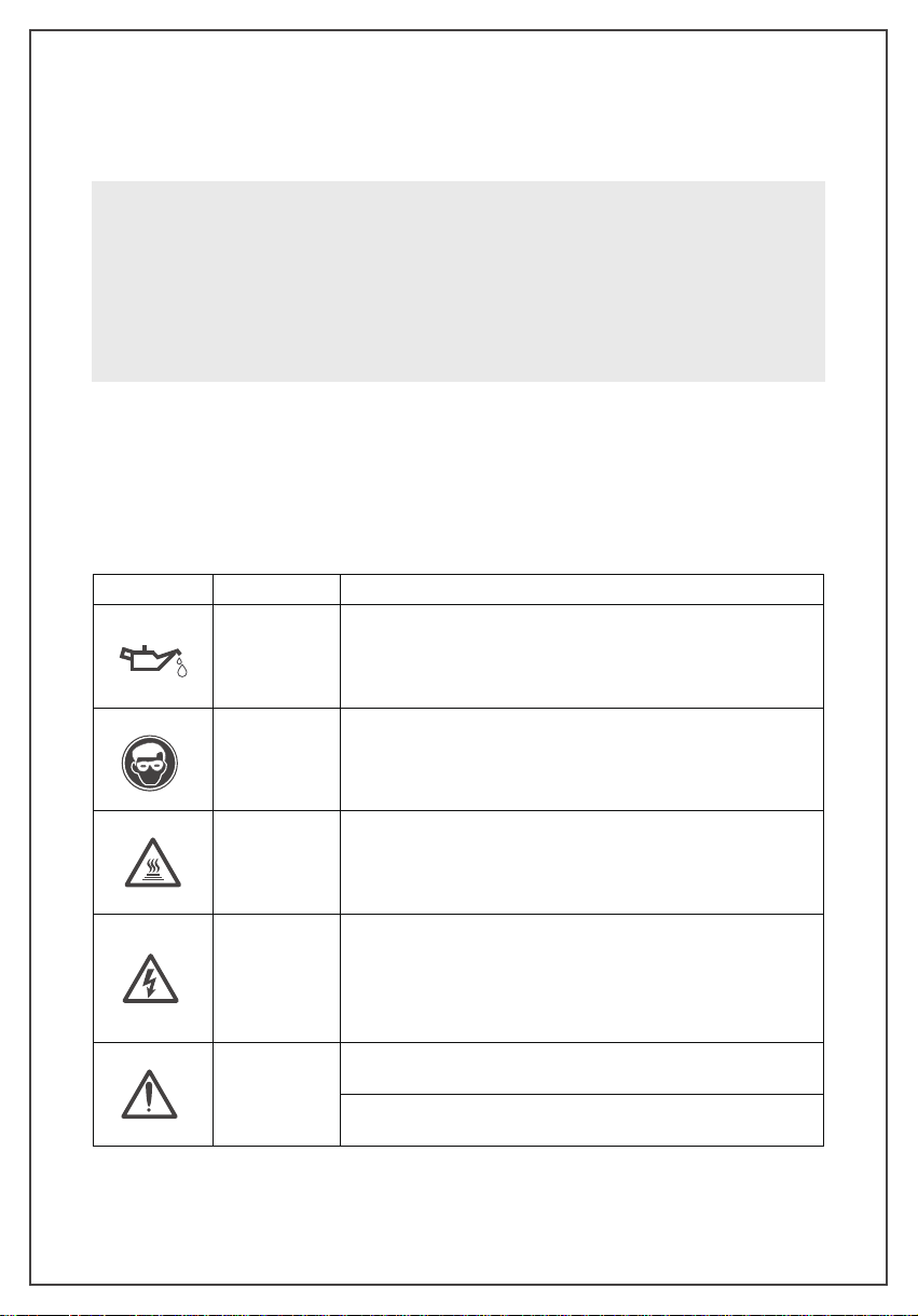
WarningSigns
• Thevacuumpumpisheavy.Becareful while handling topreventpersonalinjury.
• Use only ISO 46 mechanical oil to avoid vacuum pump damage.
• Do not cover the exhaust port during vacuum pump operation.
• Donotexposethesuctionportcontinuouslytoatmosphereformorethan3 minutes.
• The air inlet pressure should not exceed 27. 5 bar to avoid sensor damage.
-1-
Sign
Name
Content
Checkthe Oil
Level Add ISO46 mechanical oil
beforethefirstuseandkeeptheoillevel
betweenthemaximumandminimumlevel
WearGoggles
Weargoggleswhenworkingwithrefrigerants
.
Directcontactwith
refrigerantsmaycauseinjury
Bewareof High
Temperature
Burns
Thepumpsurfacebecomeshotduringnormaloperation. Donot
touchthepumpbodyormotorduringoperation
Avoid Electrical
Shock Hazards
Improperusemay causeelectricalshockhazards
Readandfollowtheinstructionscarefullyandtakeprecautionsto
avoidelectricalshockhazards . Confirmthatallassociateddevices
aregroundedcorrectlybeforepoweron
Danger
Pleaseremovetheexhaustcap beforestartingup
Checktheoillevelandprohibitrunningwithoutoil

ProductFeatures
TechnicalParameters
• Intelligent Control of Motor and Solenoid Valve
• Leakage Level Judgment
• Vacuum Change in Graph
• 4" Touch Screen Display
• Estimated Job Completion Time
•Data Logging and Storage via App
-2-
Models
SVP-7 SVP-9 SVP-12
Stage
2 stages
PowerSupply
110V / 60HZ; 220V/50HZ
Motor
AC induction motor
SpeedRegulation
Fixed speed
VacuumAccuracy
1-10000microns ±10% of Reading / ±10microns
10000-19000 microns ±20% of Reading
OperatingTemperature
5°C~40°C(41°F~104°F)
Transmission
Distance
30ft / 10m
LimitVacuum
15 microns
PumpingRate
7 CFM (3L/S) 9 CFM (4L/S) 12 CFM (5L/S)
MotorPower
3/4 HP ( 550 W ) 1 HP ( 750 W ) 1 HP ( 750 W )
FuelVolume
22oz /(650ml) 22 oz /(650ml) 25.3 oz(750ml)
OverallDimension
18.5in×10.5in×14.8in / (470mm*267mm*380mm)
Weight
34.2lbs / 14.8kg 35.3lbs / 15.3kg 36.8lbs / 16kg
AirInlet
1/4 SAE ;3/8 SAE

ServiceParts
① Display screen
② Handle
③ Air inlet
④ Solenoid valve
⑤ Catcher
⑥ Oil tank
⑦ Base
⑧ Motor
⑨ Motor housing
⑩ Power button
⑪ Vacuum sensor
⑫ Oil window
⑬ Oil drain plug
-3-
1
9
8
7
6
5
2
43
12
13
10 11

OperationGuide
InterfaceIntroduction
Conditions that must be met
1. Place on a flat surface.
2. Confirm the voltage and frequency at the outlet match with the vacuum pump
specifications.
3. Confirm the oil level is within the Min and Max level.
4.Remove the air inlet cap(1/4 SAE fitting as shown in the
right image), connect the pumped system(make sure the pipe
fitting is fit with the air inlet fitting). Tighten the air inlet and
make sure the system and hoses are sealed with no leakage.
5. Plug in the power cordand open the exhaust port.
Maininterface
-4-
SVP-7 (110V)
Measure Graph Sengs System
16:22:34 Record: OFF
Start
1/4 SAE

(1) Thestatusbarontop ofthepageshowsthe product model,time,Bluetoothstatus
andrecordstatus.
①Model numbers varies depending on the product models.
② Bluetooth not connect; Bluetooth connected.
③During operation, appear when temperature exceeds the upper alarm limit,
and appear when temperature below the lower alarm limit.
④Record: close means no data is recorded.Record: Open means that data is
being recorded.
(2) The middle part of the page is the sub-interface button.
① : Real-time measurement interface
② : Graph
③ : Vacuum parameter setting
④ : System parameter display and setting
(3) Thebottompartisthe “Start” and“Stop”button. Themotoriso bydefaultafter
power-on. Click “Start” to start the motor. Button will be locked (within 3 sec);
Click “Stop” to stop the motor. Button will be locked (within 10 sec).
After the motor stops, in order to prevent frequent start and stop, the button is
invalid within 10 seconds.
When the motor starts, the solenoid valve automatically opens instantly. The
solenoidvalveclosesautomaticallyafter the motor stopstoavoidtheoilbesuck to
vacuum sensor.
1. Real time measurement interface
Clickthe“Measure”buttononthemaininterfacetoenterthereal-timemeasurement
interface.
-5-

(1) Motor Status: show the current status of the motor.
(2) Motor Temp/Limit: show the surface temperature of the pump chassis and set
the alarm temperature.
(3) OilTemp/Limit:show vacuumpumpoiltemperatureandsetthealarmtemperature.
(4) Vacuum Status: display the current vacuum value status, "Decrease", "Stable",
"Rise", "--".
(5) Estimated End Time: when the vacuum is stable, it shows the estimated job
completiontimeincludingholdingtime.
(6) Vacuum Reading Display: Vacuum readings shows when the vacuum of the
system in real-time is below 60000microns. The waiting time for the vacuum
reading is longer for a larger system.
Note: The vacuum reading varies due to the sensor placement dierent. The reading
variances is caused by the uneven air flow during the vacuuming process. The farther
the air from the pump, the higher the air density is thus the vacuum reading is higher.
(7)Leakagelevel: when the vacuum is stable, checktheleakage possibility from 0 to
100 levels. 0 represent uncertain leakage. The larger the number, the greater the
possibility of the leakage.
(8) Key: return to the main interface.
2. Graph
Clickthe“Graph”buttononthe maininterfaceto viewthevacuumchangeinrealtime.
(1) When the vacuum value drops below 60000microns, the vacuum change graph
is displayed.
(2) The X axis represent time. Y axis represent vacuum. The vacuum value is from
0-60000microns.
(3) Key:return tothemaininterface.
-6-
Return
Return

3. Settings
Click the “Settings”button on the main menu to enter the setting interface.
Unit(P/T)
SelectUnitto settheunitforvacuumand temperature.Theselectedunits areingreen.
Vacuum
Set the minimum vacuum value, logging interval, and recording status.
(1) MinimumVacuum:setthetargetvacuumvalue.Therangeof theminimumvacuum
valueis8-750microns.Clickthechangebuttontoswitchtheminimum vacuumvalue;
the display unit changes according to the selected unit.
(2) Logging Interval (S):1, 5, 10, 30, 60, 120, 300.
(3) Recording Status: The logging can be turned on and o. The upper right corner
shows the logging/recording status.
-7-
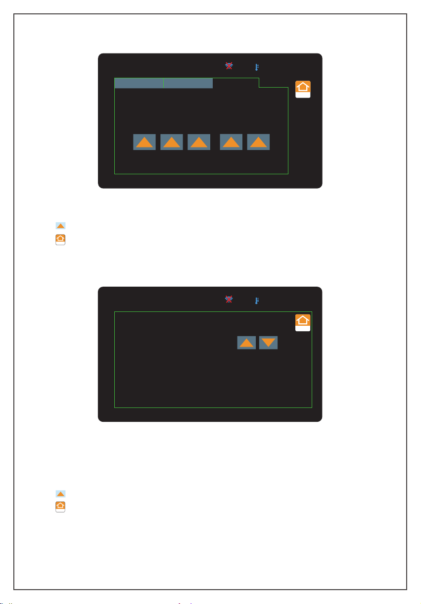
Time
(1) Set and save the time then it shows at the top of the screen.
(2) : Change key.
(3) : return to the main interface.
SVP-7 (110V) 16:22:34 Record: OFF
Return
Unit(P/t) Vacuum Time
M D Y
9 / 12 / 20 HMin
16 : 22
-8-
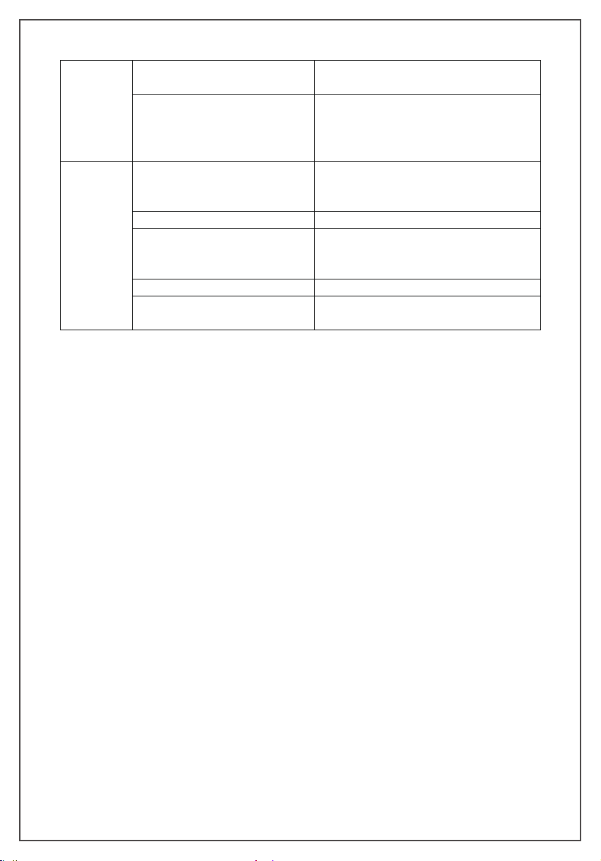
Return
SVP-7 (110V)
Running Time:
Holding Time:
Flow Rate:
3 Min
0 Min
7 CFM
16:22:34 Record: OFF
Return
4. System
In the main menu, click the “ System” button to enter the system interface.
(1) Running Time: refer to theaccumulatedrunning time of themotor.
(2) Holding Time: refer to the time for the vacuum pump to continue vacuuming
after the target vacuum value is stable.
(3) Flow Rate: refer to the pumping speed of the vacuum pump.
(4) : Change key.
(5) : return to the main interface.
Return

Other functions
1. Temperaturealarm:Whentheoiltemperatureormotorchassistemperature exceeds
theupperlimitalarm temperature setbytheAPP,themotorand solenoid valveare
closed,thetemperaturealarm icon" "isdisplayed atthetopofthe screen;When
thetemperaturedecreasewithinthealarmtemperature,thealarmwillbecleared,and
thevacuumworkcontinues.Iftemperatureexceedstheoinealarmtemperature,the
temperaturealarmicon" "willbedisplayedonthetopofthevacuumpumpscreen,
themotoroperationwillnotbeaected.
5. After using the vacuum pump
1. Closethe valvebetweenthepump andthepumpedcontainer.
2. Turn o the power switch on the pump, unplug the power plug, and remove the
connectingpipe.
3.Finally,closethe airinletcapto preventdirtorfloatingparticlesfrom enteringthe
pumpcavity.
CareAndMaintenance
Precautions
-9-
1. When the vacuum is started, the air pressure is relatively high and the pump
exhaustvolume islarge,thusoilmist will beoverflowingwithalarge amount of
gas.Thisisacommonphenomenonforarotaryvanevacuumpump.
Whenthevacuumdrops to avery low level, thepumpexhaustvolumeissmall,
andtherewill benooilmist.Therefore,usershould regularlymonitorthe oillevel
viatheoilwindowtoavoidrunningoutofoil.
2.During operation,storage and transportation, keep the vacuum pumpcleanto
prevent pollutants such as water, mechanical impurities,etc.fromenteringthe
pump so as not to aect the service life of the vacuum pump and the normal
operationofthesystem.
3.Theoilinthepump should be drained if it is not usedforalongtime.Storethe
pumpinadry and clean environment.
4.The diameter ofthe pipe islarger than theinner diameter ofthe air inletto avoid
aectingthepumpingspeed.
5.Checkthe tightnessof thepipe connectionto preventleakage. Recommendusing
thevacuumgreaseontheconnectionandclampitwithaclamptoensuretheseal.
6.Donotusethepumptopump outgaseswhich containhighlevelofoxygen,metal
corrosiveandexplosivegases.Inaddition,donotpumpinanygasesthat react
withpumpoilandcontaininglargeamountof watervapor.
7.Itis recommendedtocleanthecatcheronceeveryhalfyear.

TroubleshootingGuide
-10-
Failure
Phenomenon Cause of Issue Troubleshooting Method
Low Vacuum
1. InsucientOil Add oil between the maximum and minimum
level
2. Pump oil Emulsified, Polluted
Replace with new oil
3. The Oil Inlet Is Blockedor the Oil
Supply is Insucient
Clean the oil inletand filter
4. Leakage of the Pump System and
Connection
Check the system and the connection to
prevent the leakage
5. Improper Selectionof Pump Check the size of the pumped container,
recalculate and select the appropriate type of
pump
6. Parts Wear and Tear due to Long
Time Used.
Repair or replace with a new pump
OilLeakage
1. The Oil Seal Is Damaged Replace oil seal
2. Looseor D
amaged
Tank
Connections
Tighten the screws and replace the O -ring
How to replace the vacuum pump oil
1. Runthepumpforabout3-5minutesuntilitiswarmeduptorunsout the pumpoil.
2. Whenthepumpisrunning,opentheairinletportatthesametimetolet theoilflow
backtothe oil tank.Thepumpmuststop whenreplacingtheoil.
Stopthe pump and open the oil drain plug. Then open the catcher to speed up the
processofoil exhausting.
3. Tiltthepumpbody tocompletelydraintheresidual oil,andtightenthedrain plug.
4.Open the catchdeviceandadd the newpumpoil.
5.Cover the air inlet cap and start the pump to run-check the oil level after one
minute.Iftheoillevelis below the lowerlimit,slowlyaddtheoiluntil it reaches the
normal oil level. Finally, screw on the catcher.
1.Poweronthe vacuumpump.
2.TurnontheBluetooth functionofthemobilephone.
3.Openthe“ElitechGauge”APP.
APPOperatingInstructions
-11-
Fuel
Injection
1. Too Much ofOil
Drain theoil to the oil level line
2. The Air Inlet Is OverPressured for
aLong Time
Choose a pump with larger pumping speed
Diculty
Starting
1. Oil Temperature is Too Low Open the air inlet, start the motor repeatedly
or heat up the pump oil
2. Motor Failure Check and repair
3. Foreign Objects Fallen into the
Pump
Check and clean
4. Power Failure Check and repair
5. The Power Supply Voltage Is Too
Low Check the powersupply voltage

4. Click"AddDevice"to enter the devicemanagementinterface.Andthe devices that
can be connected are displayed in red. Click on the top right of the device to
establish aconnection.Aftersuccessful connection, the device barturnsgreenand
the Bluetooth icondisplays .
5. For the connected device, click “+”at the bottom right of the device to add the
device to the work interface. The bottom of the screen shows that the device has
been added successfully.
6. Clickthereturnbuttoninthe upper left cornerofthedevicemanagementinterface
to enter the workinterface.
-12-

-13-
The interface includes historical devices and the new devices.
(1) The history device displays the previously connected devices, click the device bar
toautomaticallyconnectthedevice.Whenthe connection is successful, and" "
is displayed in the upper left corner.
(2) : after clicking it will search for new devices.
(3) : Bluetooth is not connected, click and try to connect this device.
(4) : Bluetooth has been connected successfully, click to disconnect.
(5) : Motor stop status, click to start running.
(6) : Motor running status, click to stop the motor.
(7)Real-time vacuum value: display the real-time vacuum value.
Screenshot
Historical device
Device name
Mac address
Search to add
a new device
Real-time
vacuum value
7. Click“ ” in the top left corner of the working interface to enter the menu.
(Only some functions related to vacuum pump are described here).
(1) REPORTS
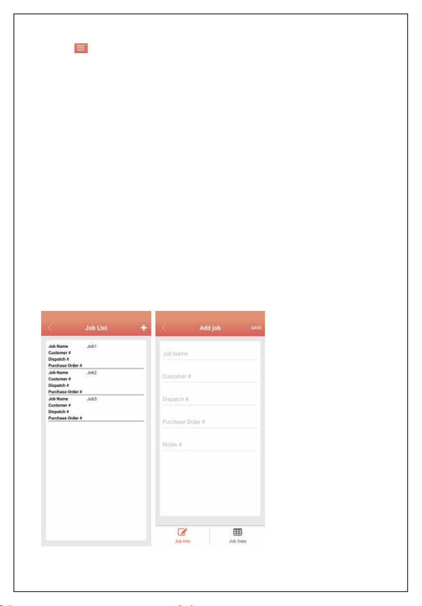
①JobSettings:Clicktheworkbuttontoentertheworklist.Addaworklistatthetopright.
Add work information and save the work.
-14-

②Reporting: Click the report button to enter the report interface.
Click the New report button, select data information by work or time, click the
chart analysis button to view historical graph, click the “Export" button at the
bottom to export data in Excel or PDF.
Click the saved report to view historical Excel and PDF reports,and long press the
report to delete.
③Screenshot Archive: save the screen capture file of the work interface. Thefile
type is PDF.
-15-

(2) CONFIGURATION
①Settings:Click the “Settings”button to enter the system settings.
Keep Screen On: control the backlight of the screen.
Switch language: select language English or Chinese.
General Alarm Preferences: single sound, single vibration or sound vibration alarm
at the same time.
②Help: Click the "Help" button to enter thehelpinterface; click the "About"button
toobtainversion information; click"Usermanual"toenterthedownload interface,
and click the "Start" button to download the vacuum pump user manual.
③Exit:Click the“Exit”button to exit the APP.
-16-

8.Device Detail
Clicktheconnecteddeviceicontoenterthedetailedinterfaceofthedevice,displaythe
vacuumpumpstatus, andcontrolthe vacuumpump.
-17-
Graph
Motorcontrolbutton
Expectedcompletion
time
Real-timevacuum
Vacuumstatus
Vacuumunitswitch
Readhistoricaldata
Leakagelevel
Temperaturestatusof
oilandshell
Editdevicename
Setlogginginterval
Recordingstatus
(1) Graph: when the vacuum valuedropsbelow60000micron,thereal-timevacuum
graph will be displayed.
(2)Expectedcompletiontime:whenthevacuumstatusisclosetostable,theremaining
vacuuming time will be displayed including the holding time.
(3)Motorcontrol: motorstop statusdisplays" ",clicktorun themotor;themotor
running status displays" ", click to stop the motor.
(4)Vacuum Value: display the real-time vacuum value.
(5)Temperature status of oil and shell: According to the setting alarm temperature,
display the temperature status "high", "normal", and "low" .
(6)Extraction Status: vacuum status display, (Rise), (Decrease), (Stable), ––
(exceed the range of vacuum sensor).

(7) Leakage Rate: under the stable state of thevacuumvalue,makeajudgmenton
the possibility of leakage of the current system, which is represented by 0-100;
0 means the uncertain of the leakage status. The larger the number, the
possibility of leakage is larger.
(8) DeviceName:modifythedevicename, supportupto 10 characters andnumbers,
click OK to confirm.
(9) Vacuum Unit: select vacuum unit,inHg, Torr, mbar, mTorr, Pa, micron, kPa.
(10) Record Switch: vacuum pump data recording switch, closed by default.
(11) Interval Time: select logging interval, 1S, 5S, 10S, 30S, 1Min, 2 Min, 5 Min.
(12) Read historical data: read the value saved by the vacuum pump while recording.
Before reading the data, it will remind whether to delete the data after reading.
9. Setting
(1) Click Settings to set parameters and alarm values of vacuum pump.
-18-
This manual suits for next models
2
Table of contents
Other Elitech Water Pump manuals

Popular Water Pump manuals by other brands


Barmesa Pumps
Barmesa Pumps 6BSE-LDS Series Installation, operation & maintenance manual

Grundfos
Grundfos MAGNA1 C Series Installation and operating instructions

Cirs
Cirs 769 user guide

JEC Pumps
JEC Pumps JRZL Series operating & maintenance manual

Simer
Simer 4850C owner's manual

KSB
KSB Sewabloc Series Installation & operating manual


