English (GB)
3
English (GB) Installation and operating instructions
Original installation and operating instructions
CONTENTS
These installation and operating instructions describe New
MAGNA1 model C.
Sections 1-5 give the information necessary to be able to unpack,
install and start up the product in a safe way.
Sections 6-11 give important information about the product, as
well as information on service, fault finding and disposal of the
product.
Page
1. General information
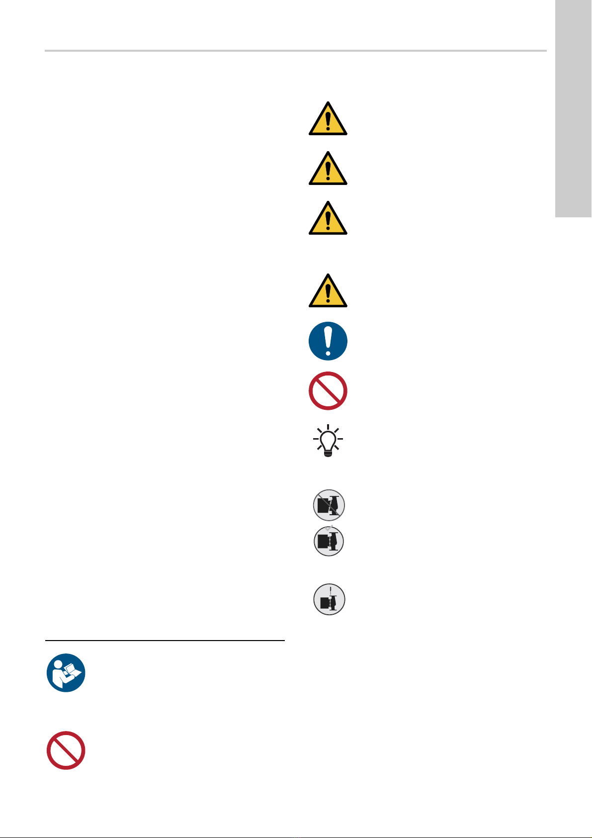
1.1 Symbols used in this document
The text accompanying the three hazard symbols DANGER,
WARNING and CAUTION is structured in the following way:
1.2 Safety symbols on the pump
1. General information 3
1.1 Symbols used in this document 3
1.2 Safety symbols on the pump 3
2. Receiving the product 4
2.1 Inspecting the product 4
2.2 Scope of delivery 4
2.3 Lifting the pump 4
3. Installing the product 5
3.1 Location 5
3.2 Tools 5
3.3 Mechanical installation 5
3.4 Electrical installation 8
4. Starting up the product 12
4.1 Single-head pump 12
4.2 Twin-head pump 12
4.3 Connecting the pump to Grundfos GO 12
5. Handling and storing the product 13
5.1 Storing the product 13
6. Product introduction 13
6.1 Applications 13
6.2 Pumped liquids 13
6.3 Identification 14
6.4 Insulating shells 14
6.5 Non-return valve 14
7. Control functions 15
7.1 Proportional-pressure curve (PP1, PP2 or PP3) 15
7.2 Constant-pressure curve (CP1, CP2 or CP3) 16
7.3 Constant curve (I, II or III) 16
7.4 Overview of control functions 17
7.5 Selecting control function 18
7.6 Operating the product 19
7.7 Pairing and unpairing twin-head pumps 20
7.8 Communication, control and monitoring 21
8. Fault finding the product 22
8.1 Grundfos Eye operating status 22
8.2 Fault finding 22
8.3 Fault finding table 24
9. Accessories 25
9.1 Insulating kits for air-conditioning and cooling systems 25
9.2 Blanking flanges 25
9.3 Counterflanges 25
10. Technical data 26
11. Disposing of the product 26
Prior to installation, read this document and the quick
guide. Installation and operation must comply with
local regulations and accepted codes of good
practice.
This appliance can be used by children aged from 8
years and above and persons with reduced physical,
sensory or mental capabilities or lack of experience
and knowledge if they have been given supervision
or instruction concerning use of the appliance in a
safe way and understand the hazards involved.
Children shall not play with the appliance. Cleaning
and user maintenance shall not be made by children
without supervision.
DANGER
Indicates a hazardous situation which, if not avoided,
will result in death or serious personal injury.
WARNING
Indicates a hazardous situation which, if not avoided,
could result in death or serious personal injury.
CAUTION
Indicates a hazardous situation which, if not avoided,
could result in minor or moderate personal injury.
SIGNAL WORD
Description of hazard
Consequence of ignoring the warning.
- Action to avoid the hazard.
A blue or grey circle with a white graphical symbol
indicates that an action must be taken.
A red or grey circle with a diagonal bar, possibly with
a black graphical symbol, indicates that an action
must not be taken or must be stopped.
Notes or instructions that make the work easier and
ensure safe operation.
Check the position of the clamp before you tighten
the clamp. Incorrect position of the clamp will cause
leakage from the pump and damage the hydraulic
parts in the pump head.
Fit and tighten the screw holding the clamp to 8 Nm ±
1 Nm.
Do not apply more torque than specified even though
water is dripping from the clamp. The condensed
water is most likely coming from the drain hole under
the clamp.


