Eliwell IWK 32x74 User manual

IWK keyboards can be used for remote
access of IWP series power board functions
by displaying functional parameters and the
operating temperature.
The Split version of the Wide device consists
of two units:
• an IWK keyboard available in several
sizes*
• an IWP power module. The IWK keyboard
is connected to the IWP power module via a
“powered” serial connection.
*Different IWK keyboard models are
available: this technical data sheet
describes the Eliwell standard 32x74 IWK
keyboard. For information on other key-
boards, refer to the relevant technical
data sheets.
Alarm
•ON for active
alarm;
•blinking when
a silenced
alarm is still
present
Fans
•ON when fan
is on;
(if active)
Defrosting
•ON when
defrosting is in
progress;
•blinking when
dripping is in
progress
compressor
•ON for relay
on (energized);
blinking for
protection
delay or
enabling
blocked
“eco”
•ON for para-
meter pro-
gramming level
2; (if present)
•blinking when
OSP reduced
set is entered
OSP
(if present)
Set point/Reduced
set point
•ON to modify
Set-Point;
•blinking when
reduced set
point is
entered
(if present)
LEDs
eco
IWK 32x74
Eliwell standard size panel keyboard for IWP boards
cod. 9IS23075
rel. 9/04
GB
fnc
set
UP Key
Scrolls through the menu items
Increases the values
Parameter programmable*
DOWN key
Scrolls through the menu items
Decreases the values
Parameter programmable*
*see IWP board instructions
esc key
ESC function (quit)
Parameter programmable*
Set point key
(press once)
MACHINE STATUS MENU
•Accesses set point
•Displays alarms
(if active)
•Displays probe values (if
present)
(hold down)
•Accesses Parameter
Programming menu
fnc
UP key +esc key pressed
simultaneously
(press for 2 seconds)
•Locks/unlocks keyboard
USER INTERFACE
The user has a keyboard with a 6 LED
display and four keys for controlling
instrument status and programming.
ACCESSING AND USING MENUS
LOCAL KEYBOARD PROGRAMMING
MENU
Hold down the “UP” and “DOWN” keys
for at least 3 seconds to access the
“Keyboard Local Programming” menu.
If specified, the access PASSWORD will
be requested (see parameter “PA3”) and,
if the password is correct, the PLO
(Local Parameters) label will appear.
This folder contains the keyboard
local parameters (see Keyboard Local
Parameters table).
If the password is incorrect, the display
will show the PA3 label again. NOTE: the
folder may NOT be visible; if this is
the case, keyboard local programming
cannot be accessed)
To enter the folder, press “set”. The label
of the first visible parameter will appear.
To scroll through the other parameters,
use the “UP” and “DOWN” keys.
To change the parameter, press and
release “set”, then set the desired value
using the “UP” and “DOWN” keys and
confirm with the “set” key. Move on to
the next parameter.
KEYBOARD LOCAL PASSWORD
Password “PA3” allows access to the key-
board local parameters. This password is
not present in the standard configura-
tion. To enable it (value<>0) and assign
it the required value, access the
“Keyboard Local Programming” menu in
the “PLO” folder.
If the password is enabled, it will be
requested when entering the “PLO”
menu.
aux
auxiliary
•ON for active auxiliary relay (if present);
•blinking if... (see IWP board instructions)
the unlit LEDs indicate:
•OFF for normal operating;
•unspecified cases;

2/4
INSTALLATION
The unit has been designed for:
• 32x74 4-key IWK keyboard: panel
mounted. Drill a 29x71 mm hole, insert
the keyboard and fix it in place with the
special brackets provided.
Do not install the keyboard in excessively
humid and/or dirty locations. It is suitable
for use in locations with normal pollution
levels. Always make sure that the area
next to the unit cooling slits is adequately
ventilated.
ELECTRICAL
WIRING
Warning! Always switch off machine
before working on electrical connec-
tions.
The unit is fitted with:
• standard 4-key IWK keyboard:
screw connectors** (or quick disconnect
connectors) for connection of electrical
cables;
**with diameter of 2.5 mm2max. (only
one conductor per terminal for power
connections): for terminal capacity, see
the label on the instrument.
ELIWELL STANDARD 4-KEY 32X74 IWK KEYBOARD
TECHNICAL DATA
Front protection: IP65.
Casing: PC+ABS UL94 V-0 resin plastic body, polycarbonate front, thermoplastic resin
keys.
Dimensions: front 74x32 mm, 30 mm depth.
Mounting: on panel, with drilling template 71x29 mm (+0.2/-0.1 mm).
Operating temperature: -5…55 °C.
Storage temperature: -30…85 °C.
Usage ambient humidity: 10…90 % RH (non-condensing).
Storage ambient humidity: 10…90% RH (non-condensing).
Display range: -50…110 (NTC); -55…140 (PTC) °C without decimal point (parameter
selectable), on display 3 digits + sign.
Measurement range: from -55 a 140 °C.
Accuracy: better than 0.5% of bottom scale +1 digit.
Resolution: 1 or 0.1 °C.
Analogue Inputs, Digital Inputs and Outputs: on associated IWP power board
Serials: see Associated IWP Power Board Technical Data Base Board-Keyboard
Connection: via “powered” serial using +12V, GND and DATA lines Consumption:
see Associated IWP Power Board Technical Data
Power supply: 12Vcfrom IWP power module.
RESPONSIBILITY AND RESIDUAL RISKS
Eliwell & Controlli s.r.l. shall not be liable for any damages deriving from:
- installation/use other than that prescribed and, in particular, which does not
comply with the safety standards specified in the regulations and/or those
given herein;
- use on boards which do not guarantee adequate protection against electric
shock, water or dust when assembled;
- use on boards which allow dangerous parts to be accessed without the use
of tools;
- tampering with and/or alteration of the product;
- installation/use on boards that do not comply with the standards and regula-
tions in force.
DISCLAIMER
This document is exclusive property of Eliwell & Controlli s.r.l. and cannot be
reproduced and circulated unless expressly authorized by Eliwell & Controlli
s.r.l.. Although Eliwell & Controlli s.r.l. has taken all possible measures to guar-
antee the accuracy of this document, it declines any responsibility for any
damage arising out of its use. The same applies to any person or company
involved in preparing and writing this manual. Eliwell & Controlli s.r.l. reserves
the right to make any changes or improvements without prior notice and at
any time.
CONDITIONS OF USE
PERMITTED USE
For safety reasons the instrument
must be installed and used in accor-
dance with the instructions supplied.
Users must not be able to access
parts with dangerous voltage levels
under normal operating conditions.
The device must be adequately pro-
tected from water and dust depend-
ing on the specific application and
only be accessible using special
tools (except for the front panel).
The device is ideally suited for
household use and/or similar use in
the refrigeration sector and has
been tested with regard to safety in
accordance with the European har-
monized reference standards: It is
classified as follows:
• as an automatic electronic control
device to be independently mount-
ed as regards its construction;
• as a 1 B type operated control
device as regards its automatic
operating features;
• as a Class A device as regards the
category and structure of the soft-
ware.
UNPERMITTED USE
The use of the unit for applications
other than those described is for-
bidden.
IWK 32x74
IWK 32x74 3/4
PARAMETER
ECO
adb
PA3
rEL
toA
Li1
tbA
* DEFAULT column: The term default identifies the standard factory-set configuration;
(!) CAUTION!
• We strongly recommend that you switch the instrument off and on again each time parameter configuration is changed in order to prevent malfunctioning of the con-
figuration and/or ongoing timings.
DESCRIPTION
ECO (folder with “PLO” label)
Type of keyboard
0= Master keyboard
1= ECO keyboard address base.
Base address. By changing the address of the power board in
a LINK, this parameter can be used to logically connect the
keyboard to a different power board so that menu naviga-
tion, parameter programming, etc is possible.
Keyboard PAssword. When enabled (value is not 0) it repre-
sents the access key for the local keyboard parameters.
reLease firmware. Device version: read only parameter.
time-out Address. tbA address timeout.
LiC (folder with “LiC” label)
Broadcast communication
n= keyboard communicates with adb address base (see.)(in
this case, there are several bases);
y= keyboard communicates with broadcast address base (in
this case, there is only one base).
Temporary navigation base address.
Temporary address for network navigation.
-1= disabled
DEFAULT*
0
0
0
0
10
n
0
RANGE
0...1
0...4
0...255
0...999
0...250
n/y
-1…4
U.M.
num
num
num
num
sec
num
num
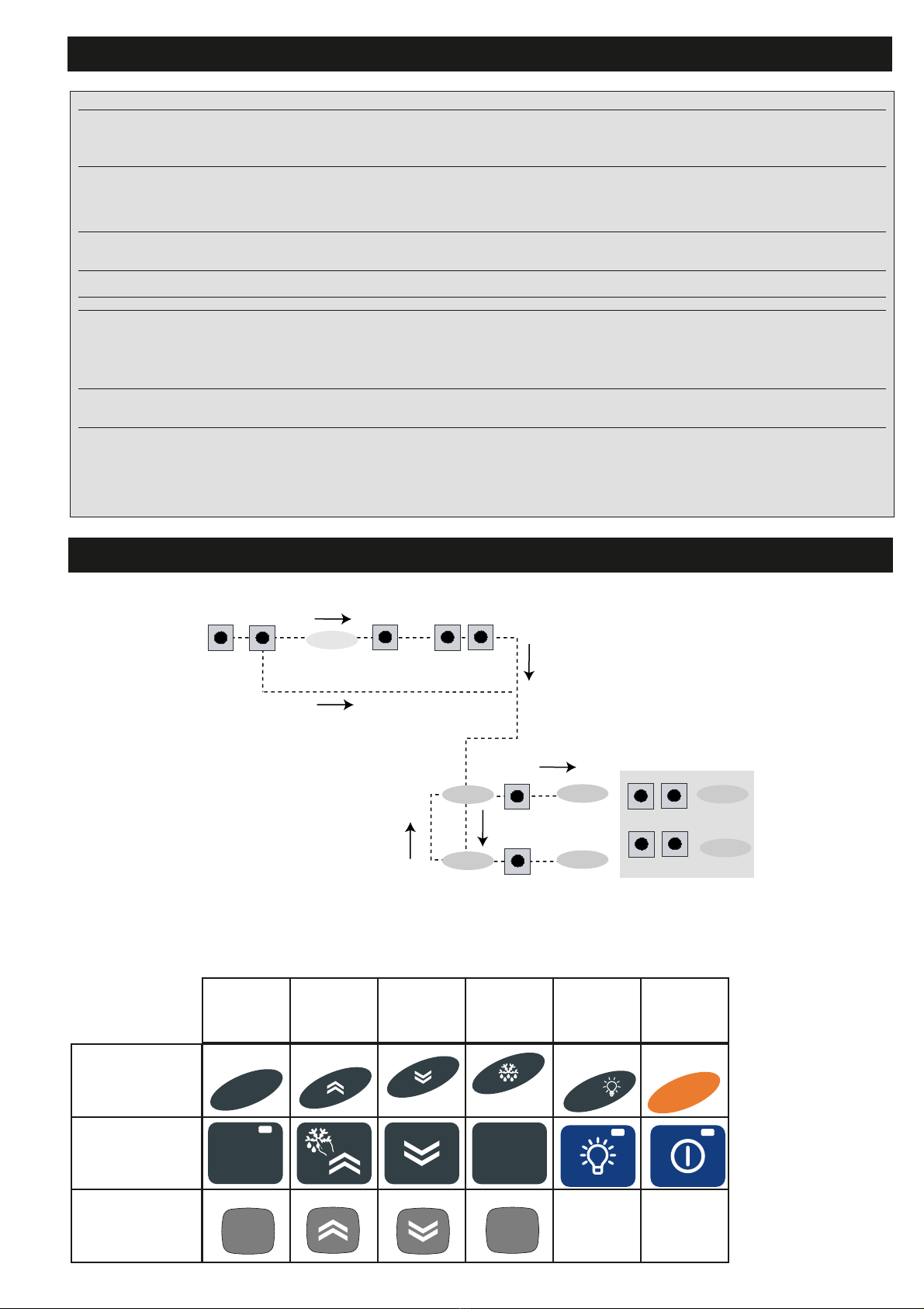
KEYBOARD LOCAL PARAMETER MENU DIAGRAMS
PLO
LiC
level par
level par
PA3≠0
set PA3 value
change
par value
scroll
parameters
press simultaneously
for 3 sec
UP DOWN ENTER UP DOWN
ENTER
ENTER
UP DOWN
UP DOWN
KEYBOARD PARAMETERS
set
aux
on/off
set esc
set fnc
wide keyboard
6-key open key-
board
32x74 keyboard
set UP DOWN ESC aux/light on/off

4/4
Eliwell & Controlli s.r.l.
Via dell'Industria, 15 Zona Industriale Paludi
32010 Pieve d'Alpago (BL) ITALY
Telephone +39 0437 986111
Facsimile +39 0437 989066
Internet http://www.eliwell.it
Technical Customer Support:
Email: [email protected]
Telephone +39 0437 986300
Climate Controls Europe
An Invensys Company
9/2004 eng
cod. 9IS23075
32x74 IWK KEYBOARD CONNECTIONS
1 2 3
KEYBOARD IWK 32x74
Serial
DATA
GND
12V
KEYBOARD IWK 32x74
DATA
12V
GND
Serial
screw
terminals
quick
conn.
TERMINALS
“POWERED”
1 GND
2 12V
3DATA
TERMINALS
“POWERED”
from left to right 12V
GND
DATA
IWK 32x74
1 2 3
IWK 32x74
123 456 7 8910
GND
485-
485+
+12V
GND
DATA
VDD
GND
BASE BOARD
485-
485+
Te l e v i s 485
DATA
GND
12V
1 2 3
IWK 32x74
LONG DISTANCE
123 456 7 8910
GND
485-
485+
+12V
GND
DATA
VDD
GND
LONG DISTANCE
12V
GND
485-
485+
DATA
BASE BOARD
485-
485+
4 5 6 7
485-
485+
Televis
Link Plus
serial
connection
NOTE : BASE UNIT/KEYBOARD
CONNECTION/PROGRAMMING.
1 — THE BASE UNIT/KEYBOARD PROGRAMMING/CONFIGURATION CANNOT BE CAR-
RIED OUT IF THE DEVICES ARE CONNECTED TO THE LINK NETWORK. THEREFORE, IT
IS FIRST NECESSARY TO CONFIGURE THE MASTER AND SLAVE DEVICES (WITH
RELATED KEYBOARDS) AND THEN CONNECT THEM TO THE LINK NETWORK.
2 — “FLICKERING” OF THE DISPLAYS ON THE KEYBOARD INDICATES THAT THE CON-
NECTED UNITS ALL HAVE THE SAME ADDRESS: DISCONNECT THE LINK NETWORK
AND PROGRAM EACH UNIT AS DESCRIBED ABOVE.
Link Plus Serial Connection
+12V 12V- power supply
GND GND “Powered” serial connection
DATA DATA- powered serial connection
RS485 Long Distance serial connection
VDD VDD 12V GND Power supply
GND RS485 485-
485- Serial connection - RS485
485+ 485 Serial connection - RS485 Serial connection
BASE UNIT/KEYBOARD WIRING
Link Plus
“long
distance”
serial
connection
(optional for
semi-finished
product)


