Elk Products ELK-MM443 User manual

Page#1
ELKPRODUCTS,INC.
PO Box 100 • 3266 US Hwy. 70 West
Hildebran, NC 28637 •USA
828-397-4200•FAX828-397-4415
http://www.elkproducts.com•Email:[email protected]
ELK-MM443
Magic ModuleAutomation Controller
Features
• Re-Programmable Logic Controller
• Four (4) supervised inputs with analog or digital sensing.
• Four (4) dry contact SPDT relay outputs.
• Two relay outputs may be jumper programmed for transistor open collector outputs.
• RS-485 four-wire data bus for networking to other Magic Modules, accessories, and personal computer.
• X-10®Power Line Carrier Interface. PL513, PSC04 (Transmit Only), or TW523, PSC05 (Two Way).
• Four (4) Accumulator Counters, range 0 to 255.
• Four (4) Timers, range 1/10 second to over 255 hours.
• 16,384 program bytes using SIMPLE programming language.
• EEProm “non-volatile” memory maintains program in the event of power loss.
• Analog transmissions between MM443’s and Preset Dim Commands.
• Dallas iButton™ TouchKey Reader with optional ELK-MA290 interface.
• Programs the ELK-MM220 (two inputs, two relay outputs module).
• Emulates ELK-MM220 for code development.
• Mounts to single or double gang electrical box.
• Optional DIN Rail Mounting. PCB mounts into 4 inch SnapTrack.
• Lifetime Limited Warranty.
06/03
Specifications
• Operating Voltage: 9.5 to 15 Volts D.C., well regulated.
• Nominal Current Draw: ~10mA., 130mA Maximum with all relays active.
• Analog Inputs: (4) rated for 0 to 13.6 volts. Optional 2k ohm End-of-line resistor supervision.
Inputs have selectable pull up or pull down jumper but may be left floating.
Software programmable high/low threshold levels.
• Analog Input impedance (floating input) - 100K ohms.
• Relay outputs: (4) form “C” relays rated for 10 Amps at 120VAC, 7 Amps at 28VDC.
Relays 3 & 4 may be configured as open collector transistor outputs, 100 ma. Maximum.
• X-10 or Access Control Interface Connector: Telephone style RJ-11 4-wire female connector is com-
patible with PL513 and PSC04 1-way modules, TW523 and PSC05 2-way modules, or with MA290
Access Module.
• Accessory Connector (J1), 5 pin male: For optional MC100 Real Time Clock, MT100 Temperature
Sensor Module, or connection for programming ELK-MM220 modules.
• RS-485 Data Bus: For connection of up to 31 additional data bus devices.
Maximum length: 4000 feet w/22AWG wire.
• Enclosure: White plastic, 6.5”W x 4.375”H x 2”D.

Page#2
OVERVIEW
The MM443 has virtually no limits and can be used as a stand alone field programmable controller in a vast array of applications
from timers, door controllers, simple process controllers, etc. or as a networked controller with other modules connected on a
common RS-485 data bus. All data bus modules are assigned a device type and up to 31 of each type may interconnected together.
A telephone style RJ-11 connector allows an X-10 Power Line Interface to be added for transmitting and receiving signals across the
AC power line. This same connector can alternately be used with our Access Interface (MA290) for reading Dallas iButton™ ID
devices or Proximity cards for identification and access control applications.
The MM443 uses the same programming software as the MM447 and MV480. The software and peripheral components are avail-
able in our Programming Kit (MK485) or Starter Development Kit (MK400). Programming is accomplished by way of a Personal
Computer (windows based) using ELK’s Magic Module Development software. Programs may be written using either the automatic
Code Writer or Application Writer interfaces which construct programs from a visual question list into a lower level Intermediate Code.
The Intermediate Code, known as SIMPLE, is a Basic-like high level language that compiles the Intermediate Code into code byte’s.
The code is then downloaded from the computer to the MM443 over the data bus using the computer’s serial port and a RS-232 to
RS-485 converter (MB485 included in the programming kit). The code is stored in Electrically Erasible Programmable Read Only
Memory(EEProm memory). The microprocessor reads out of EEProm memory and executes the code through a built in operating
system. Once programmed, the MM443 may be disconnected from the data bus or the computer may be turned off. The latest
updates to the ELK Product’s Magic Module Development Software are available at: www.elkproducts.com.
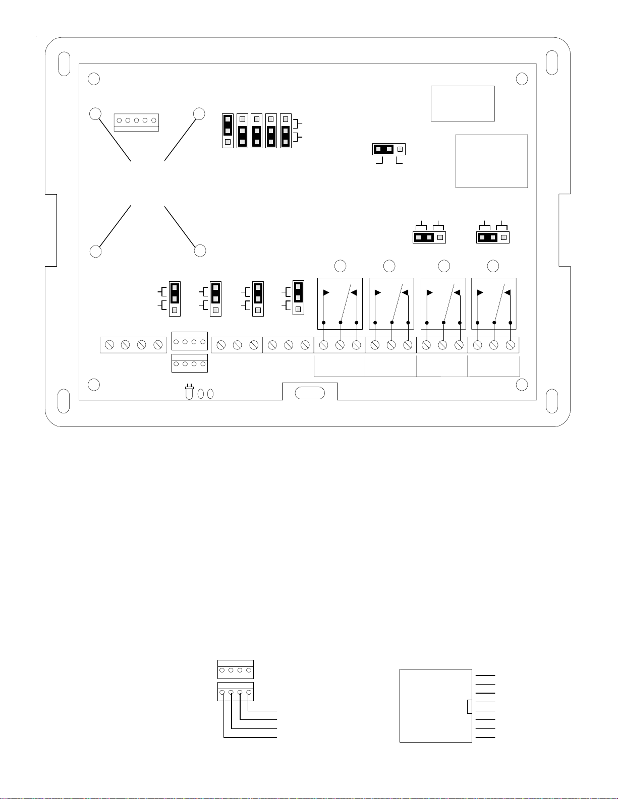
INSTALLATION and HOOKUP
1. Set the RS-485 DATA BUS ADDRESS Jumpers. Each MM443 must be set to its own individual data bus address. There are 5
plug-on DATA BUS ADDRESS Jumpers located along the top of the board. See Figure 1. Each jumper has a position of [0] or [1] and
a binary value (1, 2, 4, 8, 16) which can be read directly above each jumper. The addition of the binary values (sum total) for
jumper(s) set to the [1] position determines the data bus address. For example: Data bus address 5 is set by placing jumpers 1 and
4 in the [1] position (1 + 4 = 5). All five jumpers are required to set the address, none can be missing.
2. Connect the four wires of the RS-485 Data Bus to any remote or additional modules, or to a RS-232 to RS-485 Data Converter
(MB485). For proper operation Data “A” must connect to Data “A” and Data “B” must connect to Data “B” on the other modules. There
are two sets of Data Bus connections:
A. Screw Terminals A & B
B. Four pin header connector J2 - Pin 3 is Data “A” and pin 2 is Data “B”.
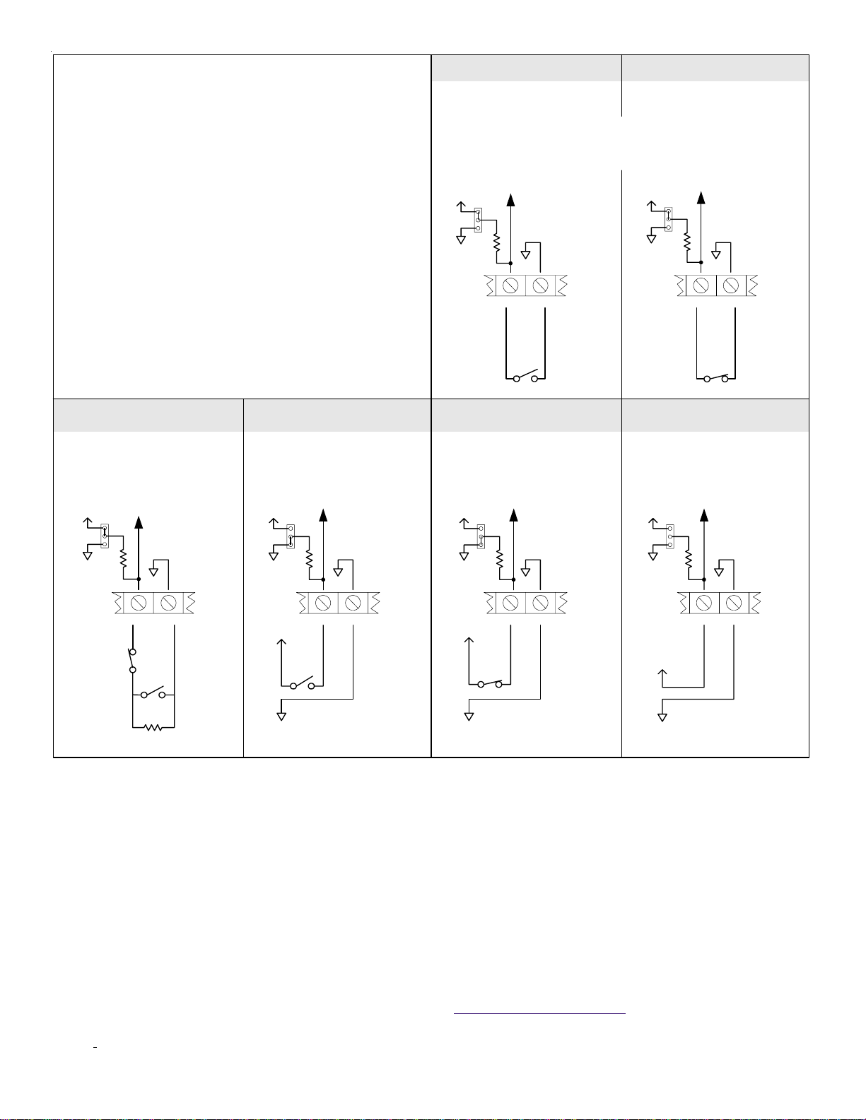
3. Connect the Inputs as needed. Four analog or digital inputs with programmable low and high level switching thresholds accept-
ing input voltages directly up to 13.6 volts DC are available at terminals 5 thru 10. Higher voltages can be used by using resistors on
the input as a voltage divider. Each input is jumper programmable for a 2K ohm input resistor pulled to 12VDC, ground, or no resistor
input voltage bias. The input loop response time may be adjusted with the set INxFilter command in 1/10-second increments from
100 milliseconds to 25.5 seconds. See Figure 2 for input configurations.
The Inputs may be used as:
A. Normally Open (Short to ground). Set JP1 thru JP4 jumper (according to the input), to the “1”(+12V) pull up setting.
B. Normally Open (Short to +12VDC). Set JP1 thru JP4 jumper (according to the input), to the “0”(GND) pull down setting.
C. End Of Line Resistor (EOLR) at 2000 ohms with Normally Open contacts across the resistor and/or Normally Closed contacts in
series with the resistor. Set JP1 thru JP4 jumper (according to the input), to the “1”(+12V) pull up setting.
D. Analog Voltage Input (0 to 13.6 VDC). Remove the JP1 thru JP4 jumper (according to the input). Use the if Inx <= value to select
what to do next in the program according to the input voltage level.
4. Connect the Relay Outputs as needed. Four form C relay outputs with contacts rated at up to 10 amps are available at screw
terminals 11 thru 22. Two relay outputs are jumper programmable (JP11 for relay 3 & JP12 for relay 4) to switch the output through an
open collector NPN transistor (100 ma maximum) to the COM terminal instead of through the relay for higher speed applications
such as flashing LED’s where the click of the relay is not desired.
5. Connect an X-10 or Access Interface as needed. To communicate over the AC powerline connect a PL513 or PSC04 X10
module (transmit only), or a TW-523 or PSC05 X10 module (two-way) to connector J5 using a single RJ-11 four wire telephone
cable. Jumper JP10 selects between the one way or two way modules. Alternatively, for Access control applications you may
connect an ELK-290 Proximity/iButton Reader Interface to connector J5. The MM443 supports both Proximity Cards and Dallas
iButtons. Note: X-10 and Prox/Ibutton applications cannot be used simultaneously.
6. Connect Power from a well regulated 12VDC power source using any of four different locations on the printed circuit board.
A. Power Input Jack, J3, (Center Pin is Positive, Barrel is Negative).
B. RS-485 Data Bus Screw terminals 1(+12V) and 4(NEG).
C. RS-485 Data Bus Four pin header connector, J2, Pins 4(+) and 1(-).
D. X-10 and iButton Interface Eight pin telco type connector, J5, Pins 2(+) and 7(-).
7. The Accessory Connector (J1) is used to program ELK-MM220 controller modules and for optional components like the ELK-
MC100 or ELK-MT100 modules. Note: To program ELK-MM220 moldules, the MC100 or MT100 modules must be temporarily
removed in order to gain access to J1.

Page#3
FIGURE 1. ELK-MM443 Terminals, Indicators, and Jumpers
LED Indicators
STATUS (D18) blinks for normal operation.
OUT1 (D5) indicates Output (Relay) 1 is ON.
OUT2 (D8) indicates Output (Relay) 2 is ON.
OUT3 (D7) indicates Output (Relay) 3 is ON (see JP11 for optional use)
OUT4 (D6) indicates Output (Relay) 4 is ON (see JP12 for optional use)
Plug-on Connectors, Jumpers, etc.
J1 ACCESSORY CONNECTOR for programming of ELK-MM220 modules,and
for optional ELK-MC100, & ELK-MT100 modules.
J2 DATA BUS Twin connectors for plug-on RS-485 data bus ribbon cables.
J5 X-10 CONN for X10 interface or ELK-MA290 Access Reader Interface.
DATA BUS ADDRESS jumpers set the MM443's RS-485 bus address.
JP1 "1" = 2K pull "up" resistor, or "0" = pull "down" resistor on INPUT 1.
JP2 "1" = 2K pull "up" resistor, or "0" = pull "down" resistor on INPUT 2.
JP3 "1" = 2K pull "up" resistor, or "0" = pull "down" resistor on INPUT 3.
JP4 "1" = 2K pull "up" resistor, or "0" = pull "down" resistor on INPUT 4.
JP10 "1 way" or "2 way" X-10 interface communication on connector J5.
JP11 "IN" = Relay 3 dry-contacts, "OUT" = Pull to ground transistor output.
JP12 "IN" = Relay 4 dry-contacts, "OUT" = Pull to ground transistor output.
TP1, short test pads upon power up to erase the program in EEProm Memory.
Terminal Descriptions
1. +12VDC • Positive Power Supply input.
2. A• RS-485 data bus. Connect all data bus "A" terminals in together.
3. B • RS-485 data bus. Connect all data bus "B" terminals in together.
4. NEG • Common Negative/ground Power Supply input.
5. INPUT 1 • Input 1
6. NEG • Common Negative/ground and return on Inputs 1 & 2.
7. INPUT 2 • Input 2
8. INPUT 3 • Input 3
9. NEG • Common Negative/ground and return on Inputs 3 & 4.
10. INPUT 4 • Input 4
11. NO • Relay 1 Normally Open
12. COM • Relay 1 Common
13. NC • Relay 1 Normally Closed
14. NO • Relay 2 Normally Open
15. COM • Relay 2 Common
16. NC • Relay 2 Normally Closed
17. NO • Relay 3 Normally Open
18. COM • Relay 3 Common
19. NC • Relay 3 Normally Closed
20. NO • Relay 4 Normally Open
21. COM • Relay 4 Common
22. NC • Relay 4 Normally Closed
124816
DATA BUS ADDRESS
JUMPERS
(ADDRESS 1 SHOWN)
SELECT X-10
JP10
POWER
J3
X-10 and DALLAS
iButton Interface
J5
RELAY 3
K4
K1 K2 K3
JP4JP3
JP2JP1
J2
J1
NO COM NC NO COM NC NO COM NC NO COM NC
RELAY 1 RELAY 2 RELAY 3 RELAY 4
1-23-4
-
BA
+
D18 TP1
0
1
PL-513 or
PSC04
TW-523 or
PSC05
2-WAY 1-WAY
JP11 JP12
Input 1 Input 2 Input 3 Input 4
0
10
1
0
10
1
DATA BUS
1234
-BA+ 1234
-BA+ IN1 IN2 IN3 IN4
4321 8765121110916151413 20191817 2221
K4K3K2K1
D5 D8 D7 D6
IN OUT RELAY 4
IN OUT
J2 1234
-BA+ 1234
-BA+ X-10 and DALLAS
iButton Interface
J5
1 = Data Bus "B"
2 = +12 VDC
3 = X10 Data Out
4 = X10 Ground
5 = X10 Data In
6 = X10 Zero Crossing
7 = Negative, Ground
8 = Data Bus "A"
2 = Data Bus "B"
4 = +12 VDC
1 = Negative, Ground
3 = Data Bus "A"
J2 Connector Pin-Out
J5 Connector Pin-Out
Optional
MC100
or
MT100
Mounts
Here
ACCESSORY
CONNECTOR
DATA BUS
MAGIC MODULE CONTROLLER (ELK-MM443)

Page#4
FIGURE 2. Configuration and Connections of Inputs
Closed Circuit N.C.
(Normally Closed) Switch
Open Circuit N.O.
(Normally Open) Switch
N.C. Switch used to activate
input from a +12V source
N.O. Switch used to activate
input from a +12V source
N.O. & N.C. Switches with a
supervising EOL Resistor Analog Input from a
0 to +13VDC source
JP
NEG
1
0
INPUT
N.O.
Switch
(Idle)
To input circuitry
NEG 2K
+12V
JP
NEG
1
0
INPUT
2K
N.O.
Switch
(Idle)
N.C.
Switch
(Idle)
EOL
Resistor
To input circuitry
NEG 2K
+12V JP
NEG
1
0
INPUT
N.O.
Switch
To Input Circuitry
NEG 2K
Input circuitry & software will see a HI
event when the N.O. switch closes, and a
LO event when the switch opens.
Set Jumper to "0" (NEG) setting.
+12V
+12V *
JP
NEG
1
0
INPUT
To Input Circuitry
NEG 2K
Input circuitry & software will see a LO
when the N.C. switch opens, and a HI
when the switch closes.
Set Jumper to NEG ("0") setting.
+12V
JP
NEG
1
0
INPUT
N.C.
Switch
(Idle)
To input circuitry
NEG 2K
+12V
JP
NEG
1
0
INPUT
To Input Circuitry
NEG 2K
Input circuitry & software will see a value
from 1 to 255 reflecting the amount of
voltage applied to the input.
Remove the Jumper.
+12V
Analog
Source
Positive
0 to +13VDC
Analog Source
Negative
*Negative connection needed if the +12v
to the switch is from an external source
N.C.
Switch
+12V *
*Negative connection needed if the +12v
to the switch is from an external source
When using
EOL
configuration,
the Hi & Low
Thresholds
must be set in
the program
The four (4) analog/digital inputs can be activated (triggered) by:
Open circuit N.O. (normally open) switches.
Closed circuit N.C. (normally closed) switches.
Open and closed circuit switches using a supervising EOL resistor.
Any device that provides a variable voltage output from 0 up to 13 VDC.
NOTE 1: For a simple open or closed circuit switch set the jumper above the
input to "1". This creates a pull-up resistor bias on the input circuitry.
NOTE 2: To drive an input HI from a device or voltage, set jumper above the
input to "0". This creates a pull-down resistor bias on the input circuitry.
Open Circuit Switches are "Open" when
idle (not active). A "Close" (or short) is
created when the switch is activated.
Closed Circuit Switches are "Closed" when
idle (not active). A "Open" condition is
created when the switch is activated.
The input circuitry & Code Writer software see an input HI event when the switch
contacts open. An input LO event is the result of the switch contacts closing.
Input circuitry & software will see a HI event
when the N.C. switch opens, a LO event
when the N.O. switch closes, and InRange
when both switches are idle (as shown)
For more information contact your local Distributor or ELK Products, Inc. - PO Box 100 - 3266 US Hwy. 70 West
Hildebran,NC 28637 USA-828-397-4200 FAX828-397-4415 -http://www.elkproducts.com
Note: Specifications and features may change without notice. All rights are reserved by ELK Products, Inc.
Dallas iButton is a trademark of Dallas Semiconductor.
ReferencetheELK-MM443 Magic ModuleSoftwareDevelopmentInstruction Manual L391foradditionalinformation.
This device complies with Part 15 of the FCC rules. Operation is subject to the following two conditions: (1) This device may not cause harmful interference, and (2) this
device must accept any interference received, including interference that may cause undesired operation. NOTE: This equipment has been tested and found to comply
with the limits for a Class B digital device, pursuant to Part 15 of the FCC rules. These limits are designed to provide reasonable protection against harmful interference in
a residential installation. This equipment generates, uses and can radiate radio frequency energy and, if not installed and used in accordance with instructions, may cause
harmful interference to radio communications. However, there is no guarantee that interference will not occur in a particular installation. If this equipment does cause
harmful interference to radio or television reception, which can be determined by turning the equipment off and on, the user is encouraged to try to correct the interference
by one or more of the following measures: 1) Reorient or relocate the receiving antenna. 2) Increase the separation between the equipment and receiver. 3) Connect the
equipment into an outlet on a circuit different from that to which the receiver is connected. 4) Consult the dealer or an experienced radio/TV technician for help.

Page#5
The ELK-MB485 is needed
for communication &
programming of the MM443
4PinPhoneCord
THE MV480 IS POWERED
FROM THE MM443
THROUGH THE DATA
BUS CABLE
NC
GND
NC
REC
AUDIO
Volume Adjust
IncreaseCW
REC/EOM
ACTIVE
LED
R1
PLAY
ACTIVE
LED
D7 D5
400 CHANNEL VOICE MODULE (ELK-MV480)
SW1
RECORD
Center Pin
is Positive
MICROPHONE
VOLUME
J2
W1 W2 W1 W2
SPKR 1 SPKR 2
-
BA
+
IN
OUT
DATA BUS 1234 -BA+ 1234
4321
-BA+
5
TO AC POWER
RECEPTACLE
12 Volt D.C.
Plug-In Power
Supply Pack
(ELK-P1216)
124816
DATA BUS ADDRESS
JUMPERS
(ADDRESS 1 SHOWN)
SELECT X-10
JP10
RELAY 3
K4
K1 K2 K3
JP4
JP3
JP2JP1
J2
J1
NOCOMNCNOCOMNCNOCOMNCNOCOMNC
RELAY 1 RELAY 2 RELAY 3 RELAY 4
1-23-4
-
BA
+
MAGIC MODULE CONTROLLER (ELK-MM443)
0
1
PL-513 or
PSC04
TW-523 or
PSC05
2-WAY 1-WAY
JP11 JP12
Input 1 Input 2 Input 3 Input 4
0
10
10
10
1
DATA BUS 1234 -BA+ 1234 IN1 IN2 IN3 IN4
4321 8765121110916151413 20191817 2221
D5 D8 D7 D6
IN OUT RELAY 4
IN OUT
P1 -
BA
+
RS-485 DATA BUS
CONNECTOR
RS-232 SERIAL
PORT CONNECTOR
RS-232 to RS-485 Data Converter
(ELK-MB485)
9 PIN
SERIAL
CABLE
To Sound Card
Speaker or Line Out
THE MB485 IS POWERED FROM THE MM443
THROUGH THE 4 PIN RIBBON CABLE
PC
To Serial COM Port
To Amplified
PC Speakers
AUDIO OUT AUDIO INSW1
DO NOT CONNECT POWER TO THE ELK-129
6' Audio Cable
5 Pin Ribbon Cable &
6' Audio Cable is included
in the ELK-129 Kit
Computer Sound Card Interface
(ELK-129)
X-10 and
DALLAS iButton
Interface
J5
8 OHM
SPEAKER
678
J1
Center Pin
is Positive
POWER
J3
LEAVE THIS SWITCH TURNED OFF,
LED STAYS ON WHEN POWERED
X-10
2 WAY
POWERLINE
INTERFACE
(ELK-PSC05)
4 Conductor Cable
22 AWG
124816
DATA BUS ADDRESS
JUMPERS
(ADDRESS 1 SHOWN)
0
1
POWER
J3
MOVE "MIC" JUMPER TO
THE "OUT" POSITION
WHEN USING THE ELK-129
J1
DATA BUS
MIC
1234
-BA+
4 Pin Ribbon Cable
12345
12345
5 Pin Ribbon Cable
-BA+
RB
WG
RB
WG
Personal Computer
(Windows Based)
Needed for X-10
communications
The ELK-129 is used
to record computer
WAV files into the
MV480 if needed.
The MV480 can play up to 400
different messages out to a speaker.
Controlled from MM443 or Computer.
J1
DATA BUS
1.5 Amps
J1 is used to program
ELK-MM220 modules, and
for optional ELK-MC100, &
ELK-MT100 modules
ACCESSORY
CONNECTOR
Figure 3. Typical Application with optional ELK-MV480 & ELK-129 Connections
Table of contents
Other Elk Products Controllers manuals