Elk makes no guarantee of compatibility for any transmitter model not listed. Elk shall not be responsible if a manufacturer changes or discontinues any listed model.
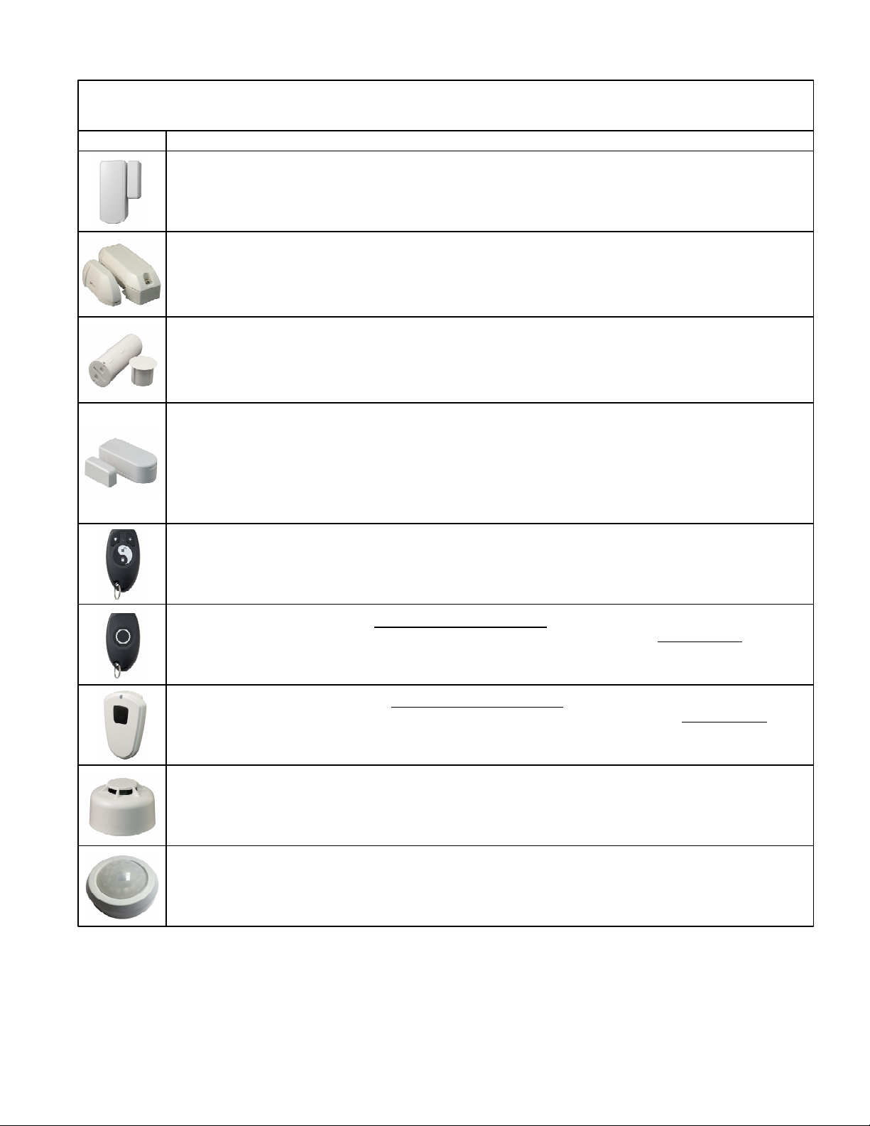
SmokeDetector‐Part#60‐848‐02‐95,orequivalent>Notes:None>EnrollProcess:Forunitswithtampersupervisionactivatethetamper,
otherwisepressthefrontTestbuttonwhichwilltransmitaviolation(alarm)>Options:SetOpt1to1(yes)forunitswithtampersupervision.
LeaveOpt2as0(no).>Loop:Setas2
SingleButtonWrist/PendantPanic‐Part#60‐906‐95,orequivalent>Notes:None>EnrollProcess:Pressandholdmainbutton>Options:
SetOpt1&Opt2to0(no)>Loop:Setas2
SingleButtonPendantPanic‐Part#60‐578‐10‐95,orequivalent>Notes:None>EnrollProcess:Pressandholdmainbutton>Options:Set
Opt1&Opt2to0(no)>Loop:Setas2
PIRMotionDetector‐Part#60‐880‐95,orequivalent>Notes:Transmitterdoesnotsendrestores.Controlautomaticallyassumesrestoral8
secondsafterviolation>EnrollProcess:Removebackcovertoactivatetamperswitch>Options:SetOpt1&Opt2to0(no)>Loop:Setas2
Door&WindowTransmitter‐Part#'s60‐362‐10‐319.5,60‐641‐95,orequiv.>Notes:ScrewterminalsallowexternalN/Oswitchtobeusedin
placeofthebuilt‐inreed.>EnrollProcess:Removebackcovertoactivatetamperswitch>Options:SetOpt1&Opt2to0(no)ifusingbuilt‐in
reedORSetOpt1&Opt2bothto1(yes)todisableinternalreedanduseexternalN/Oswitchconnectedtoscrewterminals>Loop:Setas2if
usingbuilt‐inreedORSetas1ifexternalN/Oswitchisconnectedtothescrewterminals.
DONOTUSEBOTHREEDANDEXT.SWITCHATSAMETIME.
PIRMotionDetector‐Part#60‐703‐95,orequivalent>Notes:Transmitterdoesnotsendrestores.Controlautomaticallyassumesrestoral8
secondsafterviolation>EnrollProcess:Removebackcovertoactivatetamperswitch>Options:SetOpt1&Opt2to0(no)>Loop:Setas2
PIRMotionDetector‐Part#60‐511‐01‐95,orequivalent>Notes:Transmitterdoesnotsendrestores.Controlautomaticallyassumesrestoral8
secondsafterviolation>EnrollProcess:Removebackcovertoactivatetamperswitch>Options:SetOpt1&Opt2to0(no)>Loop:Setas2
Door&WindowTransmitter‐Part#60‐499‐10‐319.5,orequivalent>Notes:ScrewterminalsallowexternalN/Oswitchtobeusedinplaceof
thebuilt‐inreed.>EnrollProcess:PressTestbuttonorTamperSwitch>Options:SetOpt1&Opt2to0(no)ifusingbuilt‐inreedORSetOpt1&
Opt2bothto1(yes)todisableinternalreedanduseexternalN/Oswitchconnectedtoscrewterminals>Loop:Setas2ifusingbuilt‐inreedOR
Setas1ifexternalN/Oswitchisconnectedtothescrewterminals.
DONOTUSEBOTHREEDANDEXT.SWITCHATSAMETIME
Door&WindowTransmitter‐Part#60‐688‐95,orequivalent>Notes:ScrewterminalsallowexternalN/Oswitchtobeusedinplaceofthe
built‐inreed.>EnrollProcess:PressTestbuttonorTamperSwitch>Options:SetOpt1&Opt2to0(no)ifusingbuilt‐inreedORSetOpt1&Opt2
bothto1(yes)todisableinternalreedanduseexternalN/Oswitchconnectedtoscrewterminals>Loop:Setas2ifusingbuilt‐inreedORSetas
1ifexternalN/Oswitchisconnectedtothescrewterminals.
DONOTUSEBOTHREEDANDEXT.SWITCHATSAMETIME
Door&WindowTransmitter‐Part#60‐741‐95,orequivalent>Notes:none>EnrollProcess:InsertBatterytopowerup>Options:SetOpt1&
Opt2to0(no)>Loop:Setas2
Heat'RateOfRise'Transmitter‐Part#60‐460‐319.5,orequivalent>Notes:none>EnrollProcess:PressTestButtonlocatedoncircuitboard
insideunitnexttobattery>Options:SetOpt1&Opt2to0(no)>Loop:Setas2
GlassBreakTransmitter‐Part#60‐873‐95,60‐834‐95,orequivalent>Notes:Opt2mustbesetto1(yes)>EnrollProcess:Activatetamper
switch>Options:SetOpt1to0(no)andOpt2to1(yes)>Loop:Setas2
ShockSensor‐Part#60‐886‐95,orequivalent>Notes:Opt2mustbesetto1(yes)>EnrollProcess:PressTestbutton>Options:SetOpt1
to0(no)andOpt2to1(yes)>Loop:Setas2
SingleButtonPanicTransmitter‐Part#60‐458‐10‐319.5,orequivalent>Notes:none>EnrollProcess:Pressmainbutton>Options:Set
Opt1to0(no)andOpt2to1(yes)>Loop:Setas2
GlassGuardTransmitter‐Part#6046210319.5>Notes:none>EnrollProcess:Presstamperswitch>Options:SetOpt1&Opt2to0(no)
>Loop:Setas2
FreezeSensorTransmitter‐Part#60‐504‐10‐95R,orequivalent>Notes:none>EnrollProcess:Presstamperswitch>Options:SetOpt1&
Opt2to0(no)>Loop:Setas2
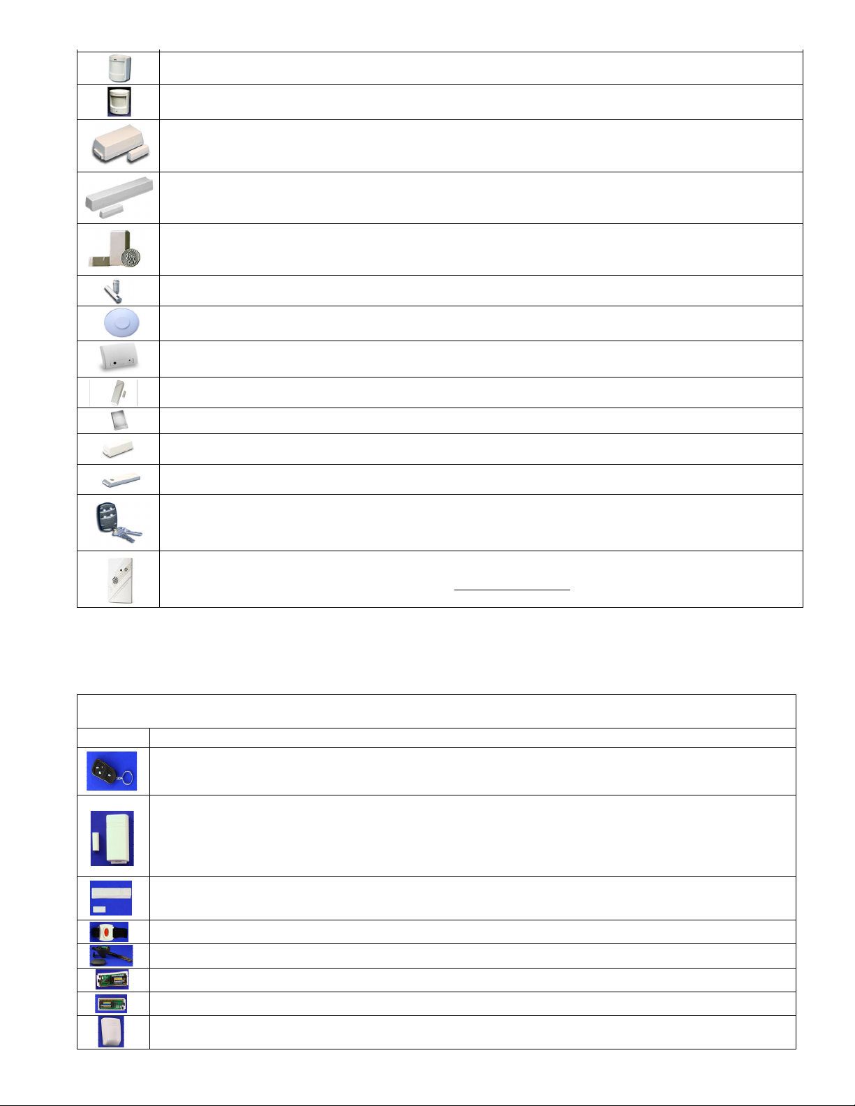
FourButtonKeyfobTransmitter‐Part#60‐606‐319.5,orequivalent>Notes:none>EnrollProcess:PressandholdtheLockandUnlock
Buttons(buttons1&2)togetheratthesametime.>Options:SettingOpt1to1(yes)willswapthe4buttonassignmentsfrom1thru4to5thru8.
Opt2shouldbeleftas0(no).>Loop:N/AAdditionalinfo:CombopressingtheLockandUnlockbuttonsatsametimewilltriggertheevent
assignedtoKey7.PressingtheLightandAsterisktogetherwilltriggertheeventassignedtoKey8.
CarbonMonoxideSensor‐Part#600‐6520‐95>Notes:none>EnrollProcess:TXIDIDnumberprintedonsensorlabelmustbeentered
manuallyintotheM1WirelessZone(Wzone)TXIDprogrammingfield.Thissensorcannotbelearnedinbythetransmissiontriportamper
methods.>Options:SetOpt1&Opt2to0(no)>Loop:Setas0ElkRPprogrammingofM1–SetZoneDefas17=CarbonMonoxideandset
ZoneTypeas0=EOL/Wireless.IntheWirelessSetupsettheEnabledboxandsetSupervisionto3=FireSupervision.
Part Number, Description, Notes, Enroll Process, Options and Loop ID
Image
Thesealternatebrandtransmitters,whenusedwithanElkM1Control,canbeenrolledfromeitherKeypadInstallerProgramming(Menu14.Sub‐Menu3)viathe
“Lrn”method,ORbyenteringtheTXIDthroughElk’sRPProgrammingSoftware.Carefullyfollowthespecifictransmitternotesoutlinedbelow.