Elk Products ELK-124 User manual

Instructions Printed On Inside
* Try these other fine ELK products *
Magic Module Series
MM443 MagicModule,4Input,4Output,Programmable
MM447 Automation Controller w/Voice,Caddx Interface
MV480 Recordable Voice Module, 400 Channels
MKHOME1 Home Control Kit for Caddx NX Controls
MK400 Starter Kit, Includes MM443 & MK485
MK485 Programming Kit, MB485, Cables, Software
MK410 X-10®Transceiver Kit, Programmed MM443
MK420 iButton™AccessKitw/MM443,MA100,MA101
MA100 iButton™‘Touchkey’ Reader & Interface Pack
MA101 iButton™‘Touchkeys’,10 pcs w/keyring holders
MA290 Proximity / Wiegand Data Interface to MM443
MB485 Data Bus Interface, RS232 to RS485
MC100 Clock / Calendar Module for MM443
ML8 Link Interface to Caddx NX Controls
MT100 Temperature Sensor Module for MM443
MM220 MagicModule,2Input,2Output,Programmable
Rust Free Sirens / Speakers
1RT Speaker & Stainless Steel Enclosure
150RT Siren & Stainless Steel Enclosure
155RT Voice Siren in Stainless Steel Box
Speakers & Sirens
44 Speaker, 30 W,8 Ohm Compact Horn
45 Siren, Compact Horn, 118db
55 Voice Siren, Compact Horn
M120 Siren, Single Tone, 107db, Mini Horn
SP15 Speaker, 15 watt, Small Horn
SP30 Speaker, 30 watt, Horn
SP35 Speaker, 20 watt, Interior
SP40 Speaker, 40 watt, Horn
SS15 Siren, Dual Tone, 110db, Horn
SS30 Siren, Dual Tone, 120db, Horn
SS36 Siren, Dual Tone, 105db, Interior
ECHO™Sirens & Speakers
73 ECHOSpeaker,20 Watt,Interior
74 ECHODualToneSiren,Interior
75 ECHO Voice Siren, Interior
870 ECHO Speaker, Self Amplified
Siren & Voice Drivers
100 High Performance Siren Driver
110 Voice Siren Driver, English & Spanish
120 Recordable Voice Module and Siren
124 Recordable Voice Module, 4 Channels
Surge Suppressors
950 Surge Suppressor, Phone & Power Line
951 Surge Suppressor, Phone - Single Line
955 Surge Suppressor, Phone - Dual Line
Relay Modules
912 Compact Relay,12 Vdc, SPDT
912B Heavy Duty Compact Relay,12/24 Vdc, SPDT
924 Sensitive Relay, 12/24 Vdc, DPDT
941 Alarm Output Director
960 Delay Timer Relay, 1 sec. to 60 min.
Power Products
1240 Battery, Lead Acid, 12v, 5Ah
1270 Battery, Lead Acid, 12v, 8Ah
12100 Battery, Lead Acid, 12v, 12Ah
12170 Battery, Lead Acid, 12v, 18Ah
12250 Battery, Lead Acid, 12v, 25Ah
P112 12 Volts DC, 1 Amp Power Supply w/Enclosure
P124 24 Volts DC, 800mA Power Supply w/Enclosure
P1216 12 Volts DC, 1.5 Amp Power Supply
P412 12 Volts DC, 4 Amp Power Supply
P624 Power Supply & Battery Charger
PD9 Power Distribution Module
965 Low Battery Cutoff and Power Switch
TRG1640 Transformer, 16.5VAC @ 40 VA
TRG2440 Transformer, 24VAC @ 40 VA
Accessories
129 Computer Sound Card Interface
800 Audio Amplifier, 10 Watts
900-2 “B” Connectors,Unfilled,500 pcs
902-2 “B” Connectors,Gel filled,500 pcs
980 Telephone Line Fault Monitor
998 Warning Alarm System Decals
999 Double Sided Tape
SL1 Strobe Light, 4 colors available
WK1 Wall Mount Kit for SL1 Strobes
For more information contact your local Distributor or:
ELKPRODUCTS,INC 828-397-4200 FAX828-397-4415
(828)397-4200 Voice
(828)397-4415 Fax
http://www.elkproducts.com
email: [email protected]
PO Box 100 • Hwy. 70W • Hildebran, NC 28637 • USA
Voice Recordable
Annunciator Module
ELK-124
FEATURES:
•Four (4) Recordable Voice Channels: Thirty (30)
seconds of message per channel, or up to 120
seconds on one channel.
•Recordings stored in nonvolatile memory
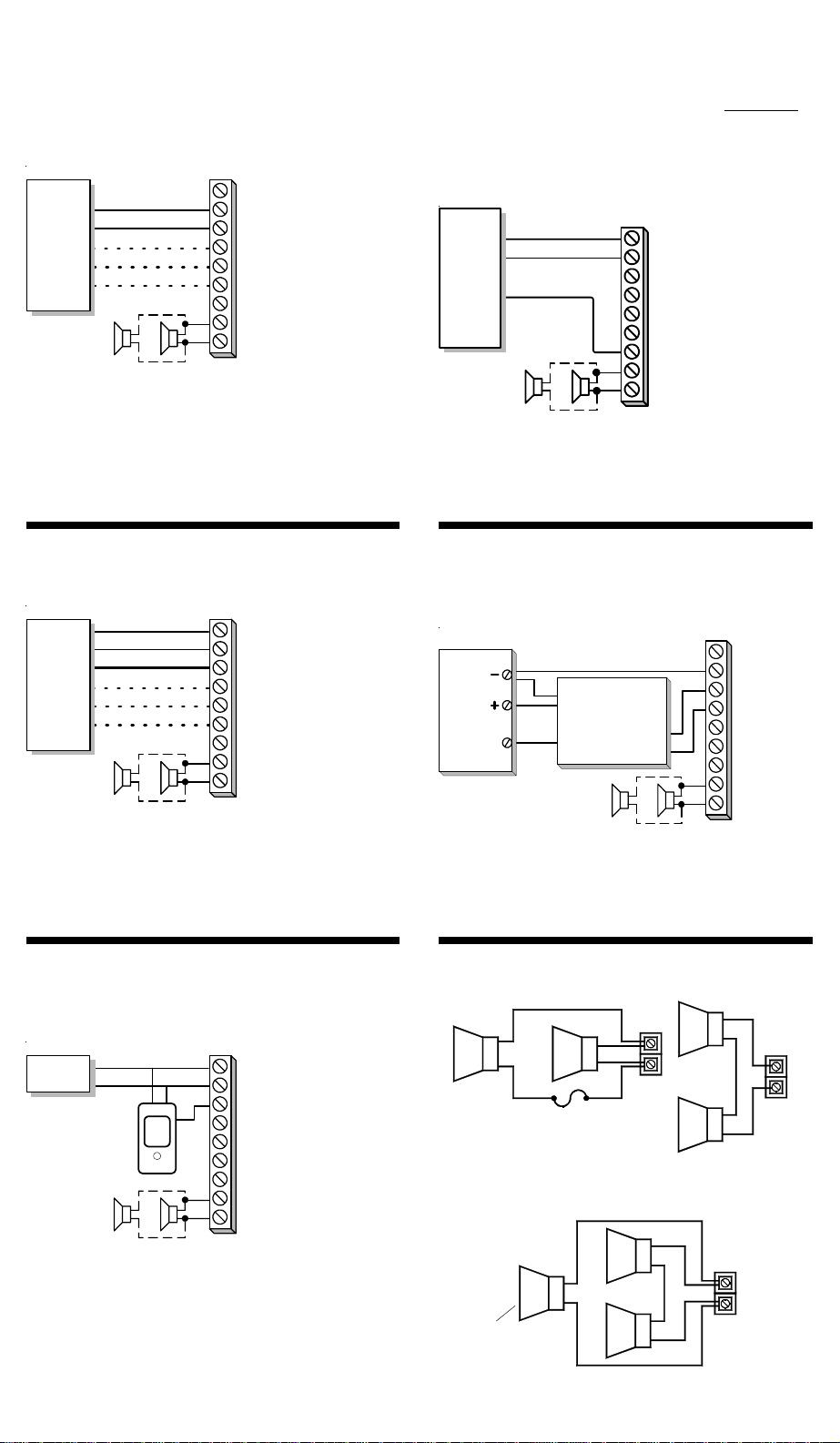
•Positive voltage triggering. Channel 1 allows
Neg. (-) triggering via the -C1 input.
•All channels accept momentary triggers
•Selectable 1 shot or continuous play modes
•Built-in condenser microphone for recording
•LED Light for Record indication
•Adjustable speaker volume and current draw
•Powerful 24 watt audio amplifier
•Fused over current protection
•PC sound card interface connectors
SPECIFICATIONS:
•Operating Voltage Range: 11 to 14 Vdc
•Adjustable current draw: 1/4 to 1.8 Amps
•Low current triggers: 11 to 14 Vdc @ 30 mA
•Maximum sound level: 120 dB @ 1meter
•Maximum speaker loading: 4 Ohms
•Maximum message length: 120 seconds
•Size: 3" x 5" x 1.25" (76 x 127 x 32 mm)
Features and Specifications subject to change without notice.
The optional ELK-129 Computer Interface may
be used to record sounds from a PC.
Voice Recordable
Annunciator Module
ELK-124
PRINTEDINUSA L332 0101
Four (4) Channels, 30 Seconds Each
APPLICATION:
The ELK-124 is a 4 channel custom recordable
voice annunciation module. Recordable chan-
nels provide 30 seconds of message each, or
they may be combined into a maximum of 120
seconds on a single channel. The channels can
be configured to play once or to repeat endlessly.

InstallationandOperation
OVERVIEW
The four (4) voice message channels on the ELK-124 are
stored in non-volatile memory and may be re-recorded as
needed. Each channel may be activated by a Positive (+)
11 to 14 Vdc input supplied from a control panel or other
switched source. Channel 1 features a Neg. (-) trigger
via the -C1 input as explained in these instructions.
CAUTION: Use of the ELK-124 as the primary
annunciator for emergency applications is not
recommended. Supplimentary or secondary
annunciator use is subject to the approval of
the local Authority Having Jurisdiction.
INPUTCONNECTIONS
[+12V] Connect to positive (+) side of a 12Vdc power
source. This input is required ONLY if the trigger
sources for channels 1 thru 4 are current limited to
30 mA or less, OR if the -C1 input trigger is being
used. Nominal operating range is 11 to 14Vdc.
[-NEG] Connect to negative (-) of a 12 Vdc power source.
[+C1] Channel 1 positive (+) 11 to 14 Vdc input trigger.
[+C2] Channel 2 positive (+) 11 to 14 Vdc input trigger.
[+C3] Channel 3 positive (+) 11 to 14 Vdc input trigger.
[+C4] Channel 4 positive (+) 11 to 14 Vdc input trigger.
[-C1] Channel 1 negative (-) input trigger. For control
panels (such as DSC) that have a switched
negative alarm output. Negative input triggering is
only available for channel 1.
NOTE: To sequentially playback multiple channels,
apply and maintain voltage triggers to multiple inputs.
[Speaker] Connect to 8 Ohm speakers. (Max. 4 Ohm load)
JumperOptions
JP1) MIC, for recording with the on board microphone.
PRG, for recording with ELK-129 computer interface.
JP2) 1SHOT, limits playback to one time per trigger.The
trigger for the channel must then be removed and
re-applied before the message will be played again.
REPEAT, message continously plays back for as
long as the input trigger is applied.
JP3) DIS SW, disables the record pushbutton switch and
prevents accidental recording.
EN SW, enables the record pushbutton switch.
JP4) GT30, enables record and playback of messages
greater than 30 seconds with message recording
overflowing** into the next channel.
30SEC, messages cannot overflow into the next
channel and are limited to 30 seconds.
Activating The Voice Channels (Playback)
Continuous (maintained) trigger: Apply a positive (+) 11 to
14 Vdc to terminal +C1 for Channel 1, terminal +C2 for
Channel 2, etc. The message will playback for as long as
the power is applied, provided Jumper JP2 ("1SHOT -
REPEAT") is in the REPEAT position. See Figure 2.
Momentary trigger: Connecting terminals +12V and Neg
to a constant (+) 11 to 14 Vdc power source allows
channels to playback with a momentary trigger input
voltage. Most current is drawn from the constant power
source. Current draw from the input triggers will be
approximately 30 mA. In the momentary trigger mode
each message is played through to the end (one cycle).
** Voice Record Time
If jumper JP4 is in the 30SEC position, maximum record
time is 30 seconds per channel. In the GT30 position,
messages longer than 30 seconds may be recorded by
overflowing the message into the next available channel.
When this occurs, the next "overflow" channel cannot be
used as a recordable channel.
WARNING: When a message exceeds 30 seconds and
overflows into the next channel (Jumper JP4 in the GT30
position), any attempt to record a message into that next
channel will automatically overwrite and destroy the
overflow part of the previous channel's message.
RecordingVoiceMessages
Place jumper JP1 in the MIC and jumper JP3 in the ENSW
position to enable the on-board microphone and record
switch. Place jumper JP2 in the REPEAT position to allow
continuous loop playback. If the message is longer than
30 seconds, place jumper JP4 in the GT30 position.
Activate the desired channel by applying a positive (+) 11
to 14 Volts DC to the input (+C1,+C2, +C3, or +C4). The
ELK-124 will playback the message (if any) that was
previously recorded. While the message is playing, press
and hold the record switch SW1. When the Red REC/
EOM LED comes on, speak clearly into the on-board
microphone. Silently release the record switch at the end
of the message. The new message will then playback.
Remove the trigger input to stop the playback. To change
the message or to correct a mistake repeat the above
procedure. To record another channel apply the trigger
voltage to that channel and repeat the above procedure.
Messages longer than 30 seconds will overflow record
into the next channel (provided JP4 is set to the GT30
position) but must be played back from the channel
where the recording began.
Note: If the maximum record time is reached or exceeded,
the red REC/EOM LED will start blinking to indicate that
recording time has halted. If this happens, the trigger
input must be removed and re-applied to start playback.
Volume and Current Adjust
Turning the Volume Increase knob clockwise in-
creases the speaker volume. The louder the volume, the
higher the current draw. The volume and current draw
may be adjusted to match the current capability of the
power supply. Maximum Current is approximately 1.2
amps with a 8 ohm speaker, 1.8 amps with a 4 ohm
speaker load.
ComputerSound Card Interface(ELK-129)
The ELK-124 may also be programmed using a personal
computer equipped with a stereo sound card and the
ELK-129 Sound Card Interface. Plug the ELK-129 into
connector J1 (CH 1+2 PRG) for channels 1 and 2, or
connector J2 (CH3+4 PRG) for channels 3 and 4. Place
jumper JP1 in the PRG position to disable the on-board
microphone. Then follow the ELK-129 Instructions.
Channel 1
+C1, -C1
Channel 2
+C2
Channel 3
+C3
Channel 4
+C4
Record Time In Seconds
FIGURE 1 - MAXIMUM MESSAGE LENGTHS
30 60 90 120
Channel 2 Channel 3 Channel 4
Channel 3 Channel 4
Channel 4
Overflow to next channel
1-SHOT REPEAT REPEAT POSITION 1 SHOT POSITION
FIGURE 2 - Jumper JP2 Selections
With shorting plug
on these two pins With shorting plug
on these two pins

8
Ohm 8
Ohm
2 Speakers in Series
Total resistance = 16 Ohms
8
Ohm
8
Ohm
3 Speakers - 2 Series, 1 Parallel
Total resistance = 6 Ohms
8
Ohm
8
Ohm
8
Ohm
Note: This speaker
will be louder than
the other two.
Low Current Trigger Method: Positive alarm
outputs capable of 30 milliamps each
The operational current will be supplied from a
constant +12 VDC auxiliary power source. The
voice channel trigger terminals draw only 30
milliamps from the control alarm outputs.
2 Speakers in Parallel
Total resistance = 4 Ohms
Alwaysadda1.5Ampfuseinserieswith
anoutdoorspeaker.Shortingoftheoutdoor
speakerwireswillblowthisfusebutother
speaker(s) will still work.
INSTALLATION&HOOKUPEXAMPLES
Security Control Panel with alarm outputs
capable of up to 1.8 Amps output. Single Alarm Output With Switched Negative:
Controls panels such as DSC provide an alarm
output with a switched negative, requiring a
special hookup.
The -C1 terminal internally activates Voice
Channel 1 upon a continuous or momentary
short to negative trigger input.
+12 Volts DC
Negative
+C1, Voice Channel 1
+C2, Voice Channel 2
+C3, Voice Channel 3
+C4, Voice Channel 4
-C1, Voice Channel 1
Speaker
Speaker
}
4 Ohm Max. Load
8 Ohm
Speakers
DSC
Security
Control
Negative
Switched
Alarm
Negative
+12VDC Power Supply
ELK-124
Short To
Negative
Alarm
Output
Note: Dashed Lines Indicate Optional Connections.
All current must be supplied from the Control
Panel Outputs. Maximum current draw with a 8
Ohm speaker load is 1.2 Amps, or 1.8 Amps with
a 4 Ohm load. The current may be reduced down
to 1/4 amp by adjusting the volume lower.
+12 Volts DC
Negative
+C1, Voice Channel 1
+C2, Voice Channel 2
+C3, Voice Channel 3
+C4, Voice Channel 4
-C1, Voice Channel 1
Speaker
Speaker
}
4 Ohm Max. Load
8 Ohm
Speakers
Ch 1
Ch 2
Negative
ELK-124
High Current,
Positive Outputs
Ch 3
Ch 4
Control
BURGLAR
FIRE
POLICE
MEDICAL
+12 Volts DC
Negative
+C1, Voice Channel 1
+C2, Voice Channel 2
+C3, Voice Channel 3
+C4, Voice Channel 4
-C1, Voice Channel 1
Speaker
Speaker
}
4 Ohm Max. Load
8 Ohm
Speakers
Ch 1
Ch 2
Negative
ELK-124
Low Current,
Positive Outputs
Ch 3
Ch 4
+12 VDC Power Supply
Control
BURGLAR
FIRE
POLICE
MEDICAL
+C1
+C2
+C3
+C4
-C1
Speaker
Speaker
+12 Volts DC
Negative
8 Ohm
Speakers
ELK-124
ELK-941
Alarm Output
Director
(Channel Separator)
Control
Alarm Output
with option for
Steady or Pulse
SingleAlarmOutputSecurityControl with
steady and pulsing alarm outputs
Separate trigger inputs can be received from a
single output control panel by using the ELK-941
Alarm Output Director to separate the steady or
pulsing outputs. See the ELK-941 Instructions.
+12 Volts DC
Negative
+C1, Voice Channel 1
+C2, Voice Channel 2
+C3, Voice Channel 3
+C4, Voice Channel 4
-C1, Voice Channel 1
Speaker
Speaker}4 Ohm Max. Load
8 Ohm
Speakers
Negative
ELK-124
+12 VDC, 1.8 Amps
ELK-624
+12 VDC
Power Supply
ELK-624
+12 VDC
Power Supply
Motion Detector
Door
Annunciator
Momentary
Output
Door Annunciator with single play message
A motion detector door annunciator may be
connected to the ELK-124 to announce entry into
a premise. The motion detector output should
momentarily switch on +12 VDC at 30 milliamps
when motion is sensed.
Set jumper JP2 to "1Shot" position for single play.
Example for Multiple Speaker Hookups
Other Elk Products Security System manuals