Elk ELK-124 User manual

PO Box 100 • Hildebran, NC 28637 • 800-797-9355 • 828-397-4200
Fax 828-397-4415 • www.elkproducts.com
Recordable Voice Module
The ELK-124 is a recordable voice module with 8
record/playback channels and up to 8 minutes of total
record time. Voice or music may be recorded making
this product ideal for applications such as: telephone
on-hold announcements, security or access control
warnings, museum narrations, and more. There are
two ways to record: 1) With the built-in microphone
and push to record button, or 2) With an optional
ELK-129 PC Sound Card Interface to transfer .wav
files from a PC. Each channel may be triggered via a
positive or negative voltage input, or a trigger switch.
Sound is delivered through a 24 watt Speaker output
as well as a line-level “RCA” jack for use with external
amplifiers, audio equipment, or paging systems
ELK-124 v3
Features
Specifications
ELK
PRODUCTS, INC.
• Eight Channels of Recordable Voice and /or Music.
• Maximum record time is 8 minutes which may be divided
between the number of channels desired.
• Recordings are stored in non-volatile memory.
• Each channel selectable for "+" or "-" triggering.
• Each channel will accept a momentary trigger.
• Continuous playback or "One Shot" settings.
• Built-in condenser microphone for recording.
• Adjustable speaker volume and current draw.
• Powerful 24 watt audio amplifier for Speakers.
• Line Level Output for Amplifiers and Paging Systems.
• Connector for opt. PC sound card interface [ELK-129]
• Housing in ELK-PB1 plastic enclosure.
• Lifetime Limited Warranty, call for details.
• Operating Voltage: 11 to 14 Volts D.C.
• Adjustable current draw: 1/4 to 1.8 Amps (depending on
volume setting and speaker load).
• Low current triggers: 6 to 14 Volts D.C. @ 30 mA.
• Maximum sound level: 122 dB @ 1 meter.
• Maximum speaker loading: 4 Ohms.
• Enclosure Size: 6.5" W x 4.375"H x 2"D, White Plastic.
07/11
Features and Specificaions subject to change without notice

Instructions ELK-124 v3
All 8 channels of the ELK-124 are recordable and can hold up to 1 minute of message each. Two or more channels can be combined into
longer messages up to the combined maximum of 8 minutes. The recordings are stored in non-volatile memory and may be re-recorded as
needed. Each channel may be activated by a Positive (+11 to 14 Volts DC) or by a Negative (pull to ground) trigger supplied from a control
panel or other switched source. Channels are individually jumper selectable for Positive or Negative trigger input source. Voice messages
are stored in non-volatile memory and may be re-recorded as needed.
Connections
Power Connections
[+12V] Connect a 12VDC power source to the +12V and NEG terminals.
[NEG] Operating voltage range is 11 to 14VDC, and the max. operating
current may reach 1.8 Amps depending on the speaker load and
the volume level selected. By connecting the ELK-124 to a full time
power source the individual channels may be tripped with either a
Pos or Neg input, and the trigger source may be low curren and low
voltage.
Channel Trigger Inputs ( 8 total )
[C1] These inputs are used for activating each of the respective
thru recorded channels. Each input may be jumper selected so that
[C8] the trip input is either a positive or negative. Refer to the
Channel Polarity Jumpers located above each terminal.
To trip with a positve voltage set the Channel Polarity jumper to
"+" and apply + 12 Volts DC. Make certain that the NEG power
connection is connected to the power source.
To trip with a negative voltage set the Channel Polarity jumper to
“-” and apply - 12 Volts DC. Make certain that the +12v power
connection is connected to the power source.
Speaker Connection
Connect to 1 or more 8 Ohm speakers. WARNING: The Max.
combined total load on this output must not exceed 4 Ohms.
Jumper Options
JP1) MIC, for recording with the on board microphone.
PRG, for recording with the ELK-129 computer interface.
JP2) REPEAT, permits the voice channel to repeatedly play for as long
as the channel input is activated.
1SHOT, restricts playback of a voice channel to only once per
activation cycle. The channel activation must be removed and
then re-applied before the message will be allowed to play again.
JP3) ENABLE, enables the record pushbutton switch.
DISABLE, disables the record pushbutton switch and prevents
accidental recording.
JP4) <60, REC led flashes when 60 secs is reached. This helps
prevent messages from accidentally overflowing into the next
channel.
>60, enables recording of messages greater than 60 seconds
with message recording overflowing into the next channel.
Activating The Voice Channels (Playback)
Continuous (maintained) trigger: Apply a positive (+) 11 to 14 Vdc to
terminal C1 for Channel 1, terminal C2 for Channel 2, etc. The message
will playback for as long as the power is applied, provided Jumper JP2
("1SHOT - REPEAT") is in the REPEAT position.
Momentary trigger: Connecting terminals +12V and Neg to a constant
(+) 11 to 14 Vdc power source allows channels to playback with a
momentary trigger input voltage. Most current is drawn from the
constant power source. Current draw from the input triggers will be
approximately 30 mA. In the momentary trigger mode each message is
played through to the end (one cycle).
Voice Record Time
If jumper JP4 is in the <60 position, the maximum record time is 60
seconds per channel. In the >60 position, messages longer than 60
seconds may be recorded by overflowing the message into the
next available channel. When this occurs, the next "overflow"
channel cannot be used as a recordable channel. Any attempt to
record a message into that next channel will automatically
overwrite and destroy the overflow part of the previous channel's
message. Note: If the maximum record time is reached or
exceeded, the red REC/EOM LED will start blinking to indicate that
recording time has halted.
Volume and Current Adjust
Turning the Volume knob clockwise will increase the output
volume. The louder the volume, the higher the current draw. The
volume and current draw may be adjusted to match the current
capability of the power source.
Options for Playback of the Voice Channels
The switches marked "Manual Triggers" are provided for
programming and for user convenience where manual activation of
the channel(s) may be desired. A constant power source must be
connected to +12V and NEG terminals in order to use these
switches.
Recording Voice Messages
Messages may be recorded from the on-board microphone, or
from a PC with a sound card and an ELK-129 interface.
To record from the onboard microphone place Jumper JP1 in the
MIC position, JP2 in the REPEAT position, and JP3 in the RECORD
position. If the message will be longer than 60 seconds, place JP4
in the >60 position. Activate the desired channel either by using
the on-board DIP switches(requires power to be connected to
+12V and NEG terminals) or by applying +12 Volts DC to the
desired input (C1, thru C8). The current message (if any) will start
to play. While it is playing, press and hold the record switch SW1
and speak clearly into the on-board microphone. Note that the
RECORD/EOM LED should light before you begin speaking. To
minimize any noise, gently release SW1 after speaking. The new
message will immediately be played. To stop the playback turn off
the channel switch or remove the trigger voltage. To re-record the
message, or to record another channel, repeat the above
procedure.
To record with the ELK-129 sound card interface place Jumper
JP1 in the PRG position, and JP2 in the REPEAT position. If the
message will be longer than 60 seconds, place JP4 in the >60
position. Plug the ELK-129 five pin ribbon cable into Programmer
Connector J1. Power the ELK-129 and move the SW1 slide switch to
CH1(this will provide power to the ELK-124). Select the channel to
record with the on-board DIP switch. Follow the instructions for
the ELK-129, Play a "scripted" WAV.
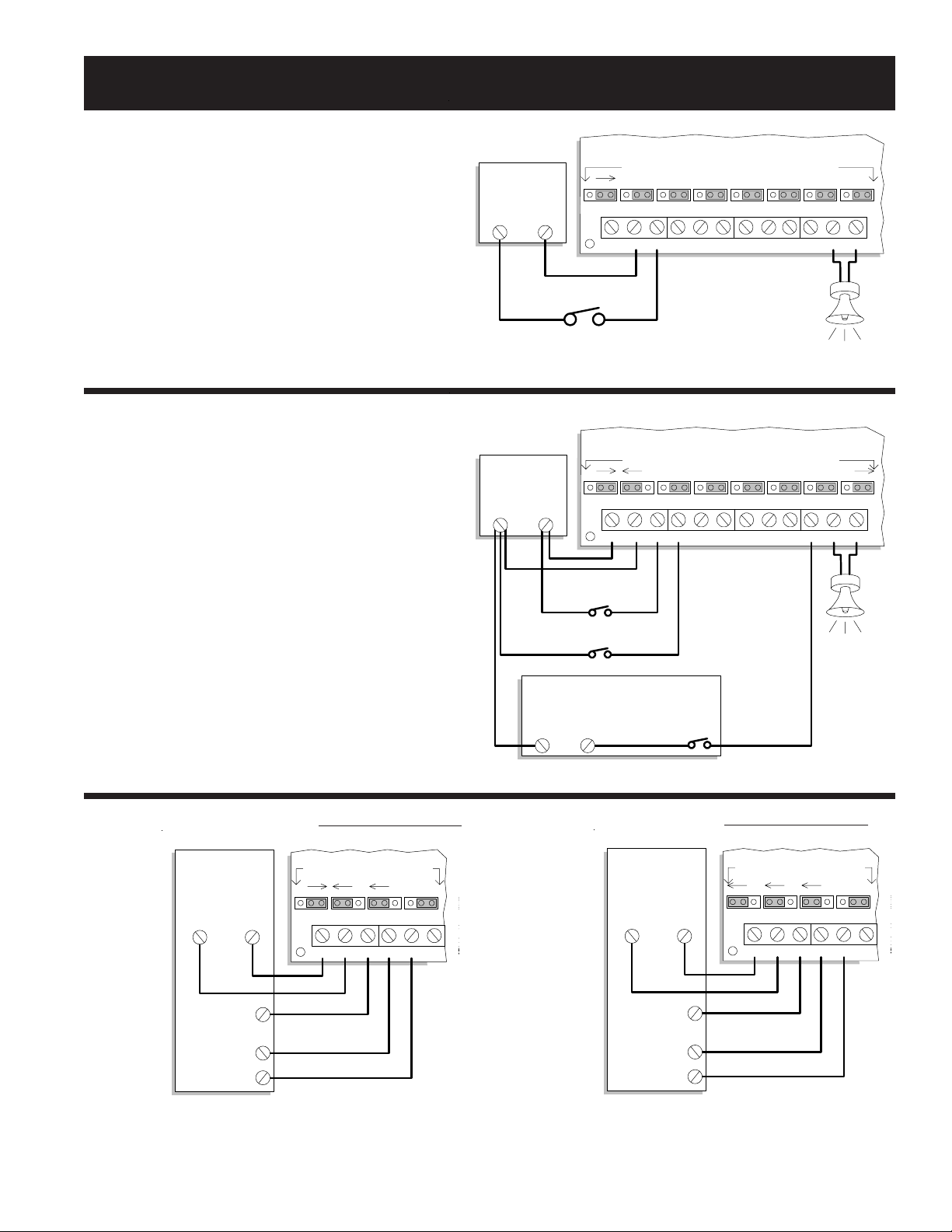
Installation & Hookup Examples ELK-124 v3
Momentary or Low Current Trigger Method alarm outputs capable of 30 mA.
The operating current is drawn from the constant +12
Volts DC power source. The channel trigger terminals
draw only 30 mA each from the control alarm outputs.
Messages play through to the end in this configuration.
Hookup to a Security Control with a Switched Negative "-"
Alarm Output
Basic Hookup
Only a +12 Volt D.C. power source is needed to play any of
the 8 channels. In this configuration, the playback will stop
as soon as power is removed from channel C1 since the
ELK-124's power terminal (+12V) is not connected to +12V.
Set the Channel Polarity jumpers to "+" for each channel
that will be activated with positive voltage.
8 Ohm
Speaker
C1+12V NEG C4C2 C3 SPEAKERC5
ELK-124 v3
C6 C7 C8
+
-
CH1
Set Channel Polarity jumpers for each channel
Close Switch to
Play Channel 1
+
-
CH2
+
-
CH3
+
-
CH4
+
-
CH5
+
-
CH6
+
-
CH7
+
-
CH8
+12 Volts D.C. Power
Source
Positive
(+)
Negative
(-)
Normally Open Switch
8 Ohm
Speaker
C1+12V NEG C4C2 C3 SPEAKERC5 C6 C7 C8
Switched Negative (-)
+
-
CH1
Set Channel Polarity jumpers for each channel
+
-
Switched Positive(+)
Normally Open Switches
or Relay Contacts
+
-
CH2
+
-
CH3
+
-
CH4
+
-
CH5
+
-
CH6
+
-
CH7
+
-
CH8
+12 Volts D.C. Power
Source
Negative
(-)
Positive
(+)
Low Voltage, Low Current Device
Negative
(-)
Positive
(+)
ELK-124 v3
C
5
-
C
C1+12V NEG C4C2 C3
+
-
CH1
Set Channel Polarity
jumpers for each channel
+
-
CH2
+
-
CH3
+
-
CH4
Security
Control
Negative
(-)
Positive
(+)
Switched
Positive(+)
Alarm Output
Switched
Negative(-)
Programmable
Outputs
+Bell
+12 Volts @ 2Amps
Hookup to a Security Control with a Switched Positive "+"
Alarm Output
This method is for Controls that switch their positive alarm
output. The alarm output plays Channel 1 while Program-
mable Outputs can be used to play Fire, Police, or Medical
messages.
C
5
-
C
C1+12V NEG C4C2 C3
+
-
CH1
Set Channel Polarity
jumpers for each channel
+
-
CH2
+
-
CH3
+
-
CH4
Security
Control
Negative
(-)
Positive
(+)
Switched
Negative(-)
Alarm Output
Switched
Negative(-)
Programmable
Outputs
-Bell
+12 Volts @ 2Amps
+Bell
This method is for Controls that switch their negative alarm
output. The alarm output plays Channel 1 while Programmable
Outputs can be used to play Fire, Police, or Medical messages.
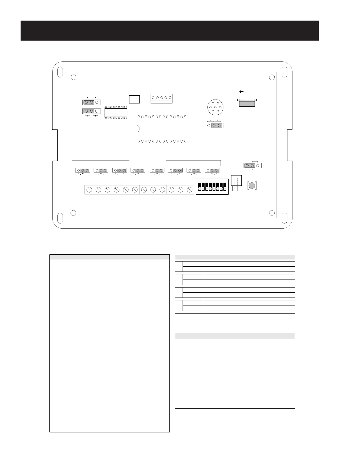
Instructions ELK-124 v3
Figure 1
C1
ELK-124 RECORDABLE VOICE MODULE
+12V NEG
R10
INCREASE VOLUME
ELK-124 v3
REC/EOM
MICROPHONE
SW1
RECORD SW
C4C2 C3 C5
LINE OUT
MANUAL TRIGGERS
REPEAT Continuously replays a channel while triggered
JP2 1SHOT Plays a triggered channel only once.
MIC Record using the on-board microphone
JP1 PRG Record using the optional ELK-129 sound interface
ENABLE Enables the on-board record switch SW1
JP3 DISABLE Disables record switch, prevents accidental recordings
Jumper Settings
1234
Message Lengths
C1 = Up to 8 Minute Recordable Voice 1 Message
C2 = Up to 7 Minute Recordable Voice 2 Message
C3 = Up to 6 Minute Recordable Voice 3 Message
C4 = Up to 5 Minute Recordable Voice 4 Message
Summary of Connection Terminals & Switches
[+12V] If using a constant 12 Volt DC power source, connect the positive
side here. Nominal operating range of the ELK-124 v3 is 11 to 14 Volts
DC. This input is only required if: A. Negative Triggering is used. B.
Momentary activation of the channels is desired. C. The activating source
equipment is current limited to 30 mA or less.
[NEG] Connect to the negative side of the 12 Volt DC power source. Also
connect the negative from external trigger inputs here if they are from
another power source.
[C1] Positive or Negative trigger input for Voice channel 1
[C2] Positive or Negative trigger input for Voice channel 2
[C3] Positive or Negative trigger input for Voice channel 3
[C4] Positive or Negative trigger input for Voice channel 4
[SPEAKER] Connect to 8 ohm speaker. (Max 4 Ohm load)
[C5] Positive or Negative trigger input for Voice channel 5
SPEAKERC7C6 C8
-+
CH1
CHANNEL POLARITY
5678
[C6] Positive or Negative trigger input for Voice channel 6
[C7] Positive or Negative trigger input for Voice channel 7
[C8] Positive or Negative trigger input for Voice channel 8
J1 PROGRAMMER
C5 = Up to 4 Minute Recordable Voice 5 Message
C6 = Up to 3 Minute Recordable Voice 6 Message
C7 = Up to 2 Minute Recordable Voice 7 Message
C8 = Up to 1 Minute Recordable Voice 8 Message
Each message location is 1 minute in length, However, messages can be recorded
over into adjacent locations to allow for longer than1 minute messages. If
message recordings exceed 1 minute they will overwrite the next adjacent
message, thus adjacent message locations become unusable. Total message
space is 8 minutes in length.
-+-+-+-+-+-+-+
JP3
ENABLE
DISABLE
JP2
REPEAT 1SHOT
JP4
<60 >60
JP1
PRG MIC
J2
<60 Message recordings cannot overflow into next channel
JP4 >60 Message recordings can overflow into next channel
Selects either a positive or negative input trigger source
for each channel
CH1 thru CH8
Jumpers
[Programmer (J1)] The optional ELK-129 Computer Sound Card
Interface module connects to this 5 pin connector to allow computer WAV
sound files to be downloaded into the ELK-124.
[Line Out (J2)] This RCA type connector provides line level sound output
for connection to Public Address amplifiers.
[Record Switch (SW1)] To record a message, set JP1 to MIC, activate
desired channel, press SW1, then speak your message into the on-board
microphone.
[Volume Control (R10)] Adjusts volume of the speaker output.
[Manual Triggers] Selects channel to be recorded. Power must be
applied to the +12V and NEG terminals to use this switch.
CH2 CH3 CH4 CH5 CH6 CH7 CH8
LED
CHANNEL
POLARITY
This manual suits for next models
1
Other Elk Control Unit manuals


