Endress+Hauser Tankvision NXA820 User manual

BA340F/00/en/04.08
Installation Instructions
Tankvision NXA820, NXA821, NXA822
Inventory Control


Table of Contents
3
Table of Contents
1 Safety Instructions . . . . . . . . . . . . . . . . 4
1.1 Designated use . . . . . . . . . . . . . . . . . . . . . . . . . . . . 4
1.2 Installation, commissioning, operation . . . . . . . . . . . 4
1.3 Notes on safety conventions and symbols . . . . . . . . . 5
2 Identification . . . . . . . . . . . . . . . . . . . . 6
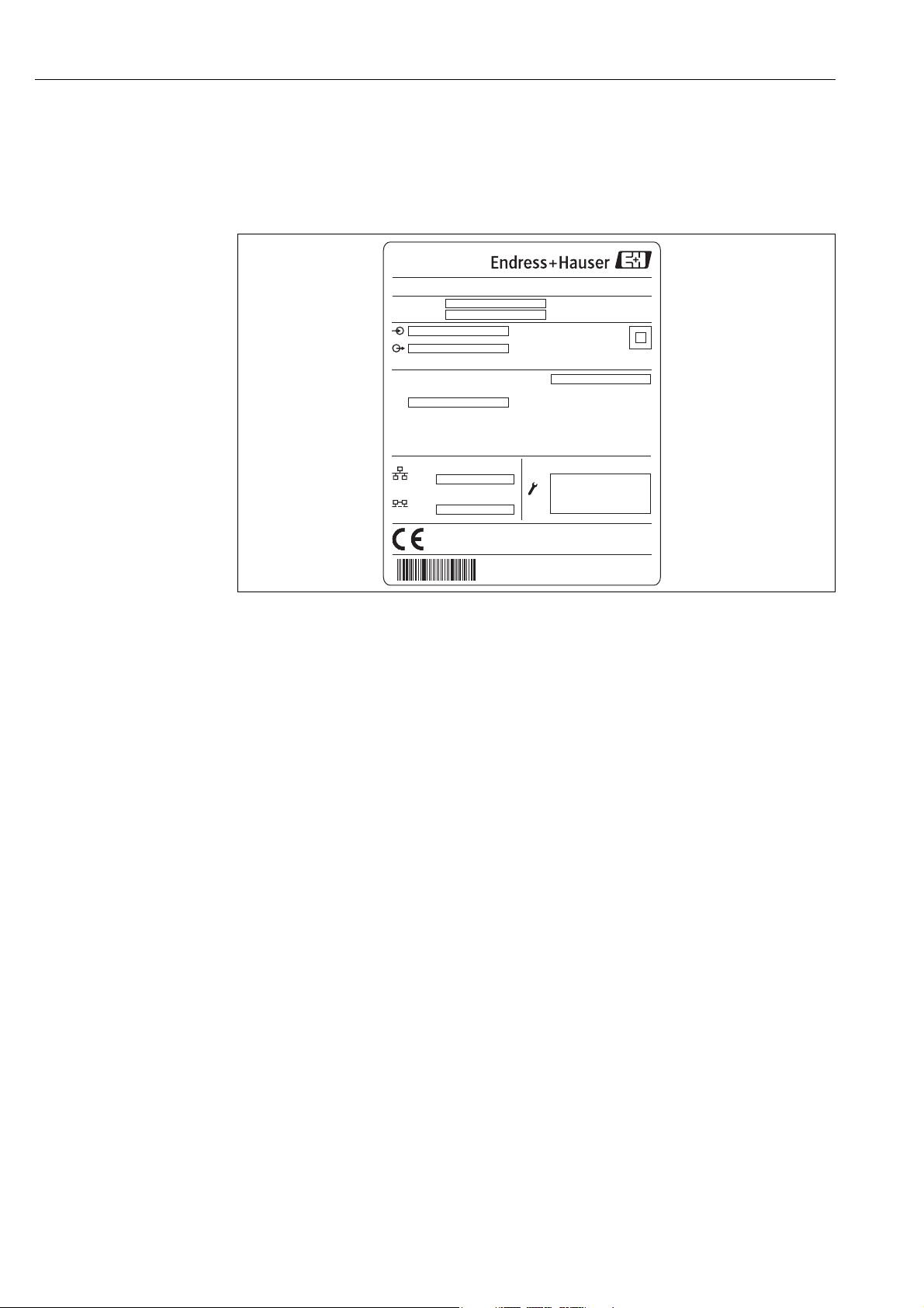
2.1 Nameplate . . . . . . . . . . . . . . . . . . . . . . . . . . . . . . . 6
2.2 Product Structure . . . . . . . . . . . . . . . . . . . . . . . . . . 7
2.3 Supplied documentation . . . . . . . . . . . . . . . . . . . . 10
2.4 Certificates and approvals . . . . . . . . . . . . . . . . . . . 10
2.5 Registered trademarks . . . . . . . . . . . . . . . . . . . . . . 10
3 Installation . . . . . . . . . . . . . . . . . . . . . 11
3.1 Incoming acceptance, transport, storage . . . . . . . . . 11
3.2 Mounting . . . . . . . . . . . . . . . . . . . . . . . . . . . . . . . 11
3.3 Installation check . . . . . . . . . . . . . . . . . . . . . . . . . 12
4 Wiring . . . . . . . . . . . . . . . . . . . . . . . . 13
4.1 Wiring examples . . . . . . . . . . . . . . . . . . . . . . . . . . 13
4.2 Terminal assignment for Tank Scanner NXA820 . . 15
4.3 Terminal assignment for
Data Concentrator NXA821 . . . . . . . . . . . . . . . . . 19
4.4 Terminal assignment for Host Link NXA822 . . . . . 21
5 Operation station settings. . . . . . . . . . 25
5.1 Deactivate proxy server usage . . . . . . . . . . . . . . . . 25
5.2 Java Runtime Environment (JRE) . . . . . . . . . . . . . . 26
6 The Tankvision operating concept . . . 27
6.1 Logging into the Tankvision system . . . . . . . . . . . . 27
6.2 The Tankvision User Interface . . . . . . . . . . . . . . . . 28
6.3 Exit the Tankvision system . . . . . . . . . . . . . . . . . . 31
7 Tankvision configuration . . . . . . . . . . 32
7.1 Network configuration . . . . . . . . . . . . . . . . . . . . . 32
7.2 Subscription Store definition . . . . . . . . . . . . . . . . . 36
7.3 Configuration of an isolated Tank Scanner NXA820 37
7.4 Configuration of a group of Tank Scanners NXA820
including a Data Concentrator NXA821 . . . . . . . . . 38
7.5 Configuration of the Host Link (NXA822) . . . . . . . 38
8 Trouble shooting . . . . . . . . . . . . . . . . 39
8.1 Test network connection . . . . . . . . . . . . . . . . . . . . 39

Safety Instructions
4
1SafetyInstructions
1.1 Designated use
Tankvision is a dedicated tank inventory system which is operated via a standard web browser. It
does not require any proprietary software.
Tankvision is based on a distributed architecture on a Local Area Network (LAN). Due to its
modular structure it can be adjusted to any application. It is ideally suited for small tank farms with
only a couple of tanks, but also for large refineries with hundreds of tanks.
Tankvision consists of the following components:
•Tankvision NXA820 (Tank Scanner)
scans parameters from tank gauges and performs tank calculations
•Tankvision NXA821 (Data Concentrator)
summarizes data from various Tank Scanners NXA820
•Tankvision NXA822 (Host Link)
provides data to host systems (such as PLC or DCS) via Modbus
1.2 Installation, commissioning, operation
The Tankvision system is fail-safe and constructed to the state-of-the-art. It meets the appropriate
standards and EC directives. However, if you use it improperly or other than for its designated use,
it may pose application-specific hazards, e.g. product overflow due to incorrect installation or
configuration. Installation, electrical connection, start-up, operation and maintenance of the devices
must therefore be carried out exclusively by trained specialists authorised by the system operator.
Technical personnel must have read and understood these operating instructions and must adhere
to them. You may only undertake modifications or repair work to the device when it is expressly
permitted by the operating instructions.

Safety Instructions
5
1.3 Notes on safety conventions and symbols
In order to highlight safety-relevant or alternative operating procedures in the manual, the following
conventions have been used, each indicated by a corresponding symbol in the margin.
Safety conventions
#Warning!
A warning highlights actions or procedures which, if not performed correctly, will lead to personal
injury, a safety hazard or destruction of the instrument
"Caution!
Caution highlights actions or procedures which, if not performed correctly, may lead to personal
injury or incorrect functioning of the instrument
!Note!
A note highlights actions or procedures which, if not performed correctly, may indirectly affect
operation or may lead to an instrument response which is not planned
Explosion protection
0Device certified for use in explosion hazardous area
If the device has this symbol embossed on its name plate it can be installed in an explosion hazardous
area
-Explosion hazardous area
Symbol used in drawings to indicate explosion hazardous areas. Devices located in and wiring
entering areas with the designation “explosion hazardous areas” must conform with the stated type
of protection.
.Safe area (non-explosion hazardous area)
Symbol used in drawings to indicate, if necessary, non-explosion hazardous areas. Devices located in
safe areas still require a certificate if their outputs run into explosion hazardous areas
Electrical symbols
%Direct voltage
A terminal to which or from which a direct current or voltage may be applied or supplied
&Alternating voltage
A terminal to which or from which an alternating (sine-wave) current or voltage may be applied or
supplied
)Grounded terminal
A grounded terminal, which as far as the operator is concerned, is already grounded by means of an
earth grounding system
*Protective grounding (earth) terminal
A terminal which must be connected to earth ground prior to making any other connection to the
equipment
+Equipotential connection (earth bonding)
A connection made to the plant grounding system which may be of type e.g. neutral star or
equipotential line according to national or company practice
Temperature resistance of the connection cables
States, that the connection cables must be resistant to a temperature of at least 85 °C.
t >85°C

Identification
6
2 Identification
2.1 Nameplate
L00-NXA82xxx-18-00-00-yy-001
1: Order code according to the product structure
2: Serial number
3: Supply voltage
4: Type of fieldbus communication (only for Tank Scanner NXA820)
5: Degree of protection
6: Admissible ambient temperature
7: MAC address of the System LAN port
8: MAC address of the Sync Link LAN port
9: Technical data of the Service LAN port
Made in Germany
D-79689 Maulburg
Tankvision
Order Code:
Ser.-No.:
250002393--
100 (Auto-MDIX)
MAC:
100 (Auto-MDIX)
MAC:
1
2
3
4
5
6
7
8
9

Identification
7
2.2 Product Structure
2.2.1 Tank Scanner NXA820
010 Approval
A Non-hazardous area
020 Field Communication; Input
8 Sakura V1 protocol, max. 10 instruments
1 Whessoematic 550, max. 15 instruments (in preparation)
4 Modbus EIA485 master, max. 15 instruments
Y Special version, to be specified
030 Power supply
1 90-250 VAC 50/60Hz
2 10.5-32 VDC
9 Special version, to be specified
040 Inventory calculations
1 Oil+gas
9 Special version, to be specified
050 Data Archive Memory Size
D 1GB; 15 parameters/min; 90 days
Y Special version, to be specified
060 Local Operation
1 status display
9 Special version, to be specified
070 Operation language
A English
Y Special version, to be specified
080 Housing
1 DIN rail mounting PBT, IP20
9 Special version, to be specified
090 Redundancy
1w/o
2 activated (in preparation)
9 Special version, to be specified
100 Custody Transfer Approval
0 not selected
1 NMI + PTB type (in preparation)
9 Special version, to be specified
110 Additional Option
A Basic version
Y Special version, to be specified
NXA820 - complete product designation

Identification
8
2.2.2 Data Concentrator NXA821
010 Approval
A Non-Hazardous area
030 Power supply
1 90-250 VAC 50/60Hz
2 10.5-32 VDC
9 Special version, to be specified
050 Data Archive Memory Size
D 1GB; 15 parameters/min; 90 days
Y Special version, to be specified
060 Local Operation
1 status display
9 Special version, to be specified
070 Operation Language
A English
Y Special version, to be specified
080 Housing
1 DIN rail mounting PBT, IP20
9 Special version, to be specified
090 Redundancy
1w/o
2 activated (in preparation)
9 Special version, to be specified
100 Custody Transfer Approval
0 not selected
1 NMI + PTB type (in preparation)
9 Special version, to be specified
110 Additional Option
A Basic version
Y Special version, to be specified
NXA821 - complete product designation

Identification
9
2.2.3 Host Link NXA822
010 Approval
A Non-hazardous area
020 Communication; Output
1 Modbus serial, / TCP/IP slave interface
9 Special version, to be specified
030 Power Supply
1 90-250 VAC 50/60Hz
2 10.5-32 V DC (in preparation)
9 Special version, to be specified
060 Local Operation
1 status display
9 Special version, to be specified
070 Operating language
A English
Y Special version, to be specified
080 Housing
1 DIN rail mounting PBT, IP20
9 Special version, to be specified
090 Redundancy
1w/o
2 activated (in preparation)
9 Special version, to be specified
100 Custody Transfer Approval
0 not selected
1 NMI + PTB type (in preparation)
9 Special version, to be specified
110 Additional Option
A Basic version
Y Special version, to be specified
NXA822 - complete product designation

Identification
10
2.3 Supplied documentation
2.3.1 Operating instructions
2.4 Certificates and approvals
CE mark, declaration of conformity
The device is designed to meet state-of-the-art safety requirements, has been tested and left the
factory in a condition in which it is safe to operate. The device complies with the applicable
standards and regulations as listed in the EC declaration of conformity and thus complies with the
statutory requirements of the EG directives. Endress+Hauser confirms the successful testing of the
device by affixing to it the CE mark.
2.5 Registered trademarks
Microsoft®, Windows®and Internet Explorer®
Registered trademarks of the Microsoft Corporation
Modbus®
Registered trademark of the Modbus-IDA, Hopkinton, MA, USA
Java®
Registered trademark of Sun Microsystems, Inc.
Document number Instrument Type of Document
BA 339F
• Tank Scanner NXA820
• Data Concentrator NXA821
• Host Link NXA822
Description of Instrument Functions
BA 340F
• Tank Scanner NXA820
• Data Concentrator NXA821
• Host Link NXA822
Installation Instructions

Installation
11
3 Installation
3.1 Incoming acceptance, transport, storage
3.1.1 Incoming acceptance
Check the packing and contents for any signs of damage.
Check the shipment, make sure nothing is missing and that the scope of supply matches your order.
3.1.2 Transport, storage
Pack the measuring instrument so that it is protected against impacts for storage and transport. The
original packing material provides the optimum protection for this.
Permissible storage temperature: 0 ... +55 °C
3.2 Mounting
3.2.1 Dimensions
NXA82xxx-06-00-00-yy-002
3.2.2 Installation conditions
• The DIN-rail housing must be mounted outside hazardous areas in a cabinet.
• The housing is mounted on a DIN rail EN 60715 TH 35x7,5 or TH 37x15.
• Do not install the instrument in the vicinity of high-voltage lines, motor lines, contactors or
frequency converters. The installation regulations for high-voltage lines, motor lines, contactors
or frequency converters must be observed.
• To ensure easy mounting and opening of the housing, a distance of approx. 1 cm should be kept
between the instruments.
43 (1.7”)
35 (1.4”)
104 (4.1”)
150 (5.9”)
140 (5.5”)
100 (3.9)
Gap ≥ 50 (2”)
Gap ≥ 50 (2”)

Installation
12
3.2.3 Mounting
L00-FMU90xxx-17-00-00-xx-001
A: Attaching the instrument to the rail; B: Detaching the instrument from the rail
3.3 Installation check
After installing the device, carry out the following checks:
• Is the device damaged (visual inspection)?
• Does the device correspond to the measuring point specifications such as ambient temperature
etc?
• If available: Are the measuring point number and labelling correct?
• Is the instrument sufficiently protected against rainfall and direct sunlight?
• Is the instrument securely mounted to the DIN rail (visual inspection)?
a
b
EN 60715 TH 35x7,5
EN 60715 TH 35x15
AB
b
a

Wiring
13
4 Wiring
4.1 Wiring examples
4.1.1 Small tank farm
L00-NXA82xxx-02-00-00-en-003
NXA820
NXA822
NXA820
Tank Scanner
NXA822
Host Link
Switch
Tank Side
Monitor Promonitor
Browser
OPC Server
Proservo
Prothermo
Micropilot
Prothermo
PLC
Fieldbus protocol
Modbus

Wiring
14
4.1.2 Refinery (up to 225 tanks)
L00-NXA82xxx-02-00-00-en-004
Switch
NXA820
NXA821
Data Concentrator
NXA820
NXA822 Host Link
NXA820
Ethernet
NXA820 NXA820
NXA820 NXA820NXA820
DCS
Operator 1
Operator 2
Operator 3
Fieldbus protocol Fieldbus protocol Fieldbus protocol

Wiring
15
4.2 Terminal assignment for Tank Scanner NXA820
L00-NXA82xxx-04-00-00-yy-019
A: Power supply; B: Fuse; C: Status relay; D: Fieldbus connection; E: Ground; F: System LAN port; G: Sync Link LAN port;
H: Service LAN port; I: Endress+Hauser CDI port; J: Display port; K: USB port; L: Weights & Measures locking switch
4.2.1 Power supply
Connector: Phoenix 7.62 GMSTB/GFKC
4.2.2 Status Relay
Connector: Phoenix FKC 2,5HC/3-St-5,08
!Note!
The depicted switching state of the relay refers to the de-energized state.
23
1
6
7
8
W&M
RESET
RESET
NXA Status
Relay
E
L+
L-
6
7
83
2
1
Fuse
POWER
10,5 ... 32V DC
2AT
10 11 12 13
10 11 12 13
MODBUS
A
B
C
D
F
G
E
H
IJ K
L
Terminal Meaning for AC version
(90-250 VAC)
NXA820 - **1********
Meaning for DC version
(10.5-32 VDC)
NXA820 - **2********
1L L+
2N L-
3 Potential equalization Potential equalization
Fuse 400 mA T Fuse 2 A T
Terminal Meaning Remarks
6 normally open contact • NXA operating normally:
terminals 7 & 8 are interconnected
• NXA powered off or fault status condition:
terminals 6 & 8 are interconnected
7 normally closed contact
8 switching contact

Wiring
16
4.2.3 Field connection
4.2.4 LAN connection
4.2.5 Additional elements in the terminal compartment
Terminal Modbus EIA4851)
NXA820 - *4*********
1) For details →Page 17
Sakura V12)
NXA820 - *8*********
2) For details →Page 18
10 A Data signal (-) B Data signal (+)
11 B Data signal (+) A Data signal (-)
12 C Signal Common not connected
13 S Capacitive Shield S capacitive shield
)Ground Ground
Socket Meaning Remarks
System LAN port Connects the instrument to the network.
Sync Link LAN port
(in preparation)
Used for connection to redundant unit.
If the primary unit fails, its task is taken over by the redundant unit.
Service LAN port Connects the instrument to a computer locally for service purpose.
Only this instrument can be configured. The Service LAN port does not
allow access to the network.
Symbol Meaning Remarks
Endress+Hauser CDI port Not used in the Tankvision instrument.
Display port For the connection of the local display in the housing cover.
Is connected on delivery.
USB port Reserved for future enhancements.
W&M Weights & Measure Switch • :W&M parameters are unlocked and can be changed.
• :W&M parameters are locked and cannot be changed.

Wiring
17
4.2.6 Additional information on Modbus EIA485
Connection
As described in the “Modbus over serial line specification and implementation guide V1.02”
published by the Modbus-IDA organisation (www.modbus.org) and based upon the EIA/TIA-485-
A physical layer specification, Modbus two-wire serial requires the following four electrical
connections between each of the devices on the bus.:
Additional bus settings
• Bus biasing resistors (must be present at one point on the bus) (always enabled inside NXA820)
• Bus termination resistor (must be present at each end of the bus) (software selectable inside
NXA820)
Cable Specification
Terminal Signal Purpose Remarks
10 A Data signal (-) These signals must be connected using a balanced twisted pair cable.
11 B Data signal (+)
12 C Signal Common Must interconnect all devices on the bus.
13 Shield EMC Protection Copper braided or combined foil and braided shielding.
Characteristic impedance 135 to 165 Ωat measuring frequency of 3 to 20 MHz
Cable capacitance ≤30 pF/m
Core cross-section ≥0.34 mm2, corresponds to AWG 22, multi-strand cable is preferred
Cable type Single twisted pair + third conductor (for common)
or
Dual twisted pair (common uses second pair with wire joined together)
Cable resistance ≤110 Ω/km
Signal damping Max. 9 dB over the entire length of the cable cross-section
Shielding Copper braided shielding or combined foil and braided shielding

Wiring
18
4.2.7 Additional information on Sakura V1
Connection
V1 Definition
V1 fieldbus is a voltage mode digital communication using up to ±30 VDC, and requires the
following three electrical connections between each of the devices on the bus:
V1 Cable specification
Terminal V1 Meaning Remarks
13 S Capacitive Shield
Connector: Phoenix FKIC 2,5/4-St-5,08
12 Not connected
11 A
10 B
)Ground Must be independently connected directly to a
primary grounding point using 4 mm2cable.
Signal Purpose Remarks
A Data signal (-) These signals must be connected using a balanced twisted pair cable.
B Data signal (+)
Shield EMC protection Copper braided or combined foil and braided shielding
Cable capacitance ≤50 nF/m
Core cross-section ≥0.9 mm2, corresponds to AWG 17, multi-strand cable is preferred
Cable type twisted pair
Cable resistance ≤30 Ω/km
Shielding Copper braided shielding or combined foil and braided shielding
Insulation ≥60 VDC

Wiring
19
4.3 Terminal assignment for Data Concentrator NXA821
L00-NXA82xxx-04-00-00-yy-020
A: Power supply; B: Fuse; C: Status relay; D: System LAN port; E: Sync Link LAN port; F: Service LAN port;
G: Endress+Hauser CDI port; H: Display port; I: USB port; J: Weights & Measures locking switch
4.3.1 Power supply
Connector: Phoenix 7.62 GMSTB/GFKC
4.3.2 Status Relay
Connector: Phoenix FKC 2,5HC/3-St-5,08
!Note!
The depicted switching state of the relay refers to the de-energized state.
23
1
6
7
8
W&M
RESET
RESET
NXA Status
Relay
E
L+
L-
6
7
83
2
1
Fuse
POWER
10,5 ... 32V DC
2AT
A
B
C
D
E
F
G H I
J
Terminal Meaning for AC version
(90-250 VAC)
NXA821 - *1*******
Meaning for DC version
(10.5-32 VDC)
NXA821 - *2*******
1L L+
2N L-
3 Potential equalization Potential equalization
Fuse 400 mA T Fuse 2 A T
Terminal Meaning Remarks
6 normally open contact • NXA operating normally:
terminals 7 & 8 are interconnected
• NXA powered off or fault status condition:
terminals 6 & 8 are interconnected
7 normally closed contact
8 switching contact

Wiring
20
4.3.3 LAN connection
4.3.4 Additional elements in the terminal compartment
Socket Meaning Remarks
System LAN port Connects the instrument to the network.
Sync Link LAN port
(in preparation)
Used for connection to redundant unit.
If the primary unit fails, its task is taken over by the redundant unit.
Service LAN port Connects the instrument to a computer locally for service purpose.
Only this instrument can be configured. The Service LAN port does not
allow access to the network.
Symbol Meaning Remarks
Endress+Hauser CDI port Not used in the Tankvision instrument.
Display port For the connection of the local display in the housing cover.
Is connected on delivery.
USB port Reserved for future enhancements.
W&M Weights & Measures Switch • :W&M parameters are unlocked and can be changed.
• :W&M parameters are locked and cannot be changed.
Other manuals for Tankvision NXA820
3
This manual suits for next models
2
Table of contents
Other Endress+Hauser Control Unit manuals

Endress+Hauser
Endress+Hauser BT10 User manual

Endress+Hauser
Endress+Hauser Tankvision Multi Scan NXA83B User manual

Endress+Hauser
Endress+Hauser analytikjena TOC module User manual

Endress+Hauser
Endress+Hauser Micropilot FMR5 series User manual

Endress+Hauser
Endress+Hauser VU340 User manual

Endress+Hauser
Endress+Hauser Nivotester FTR325 User manual

Endress+Hauser
Endress+Hauser TMD1000 TMD1 User manual

Endress+Hauser
Endress+Hauser Tank Side Monitor NRF590 User manual

Endress+Hauser
Endress+Hauser CYA251 User manual

Endress+Hauser
Endress+Hauser Prosonic S FMU90 User manual