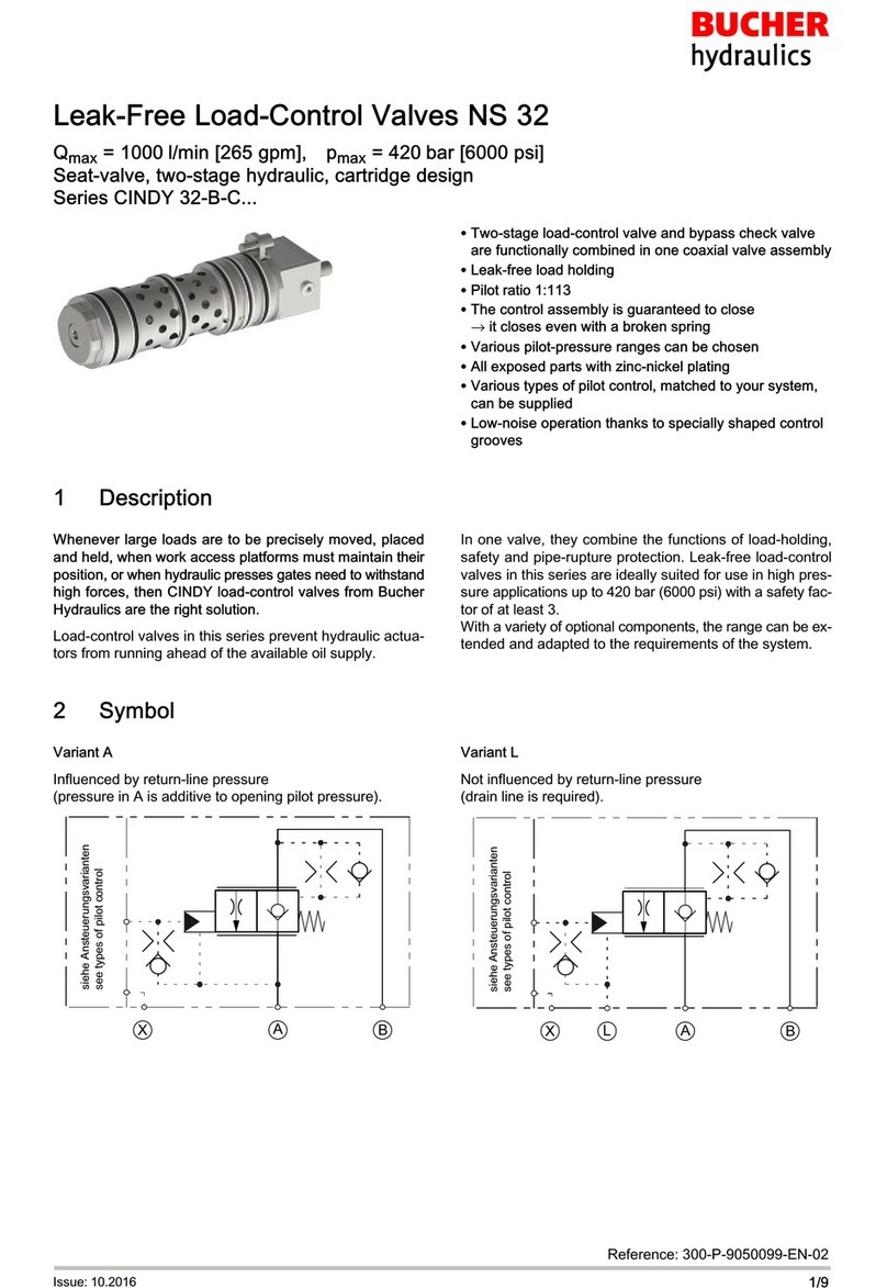
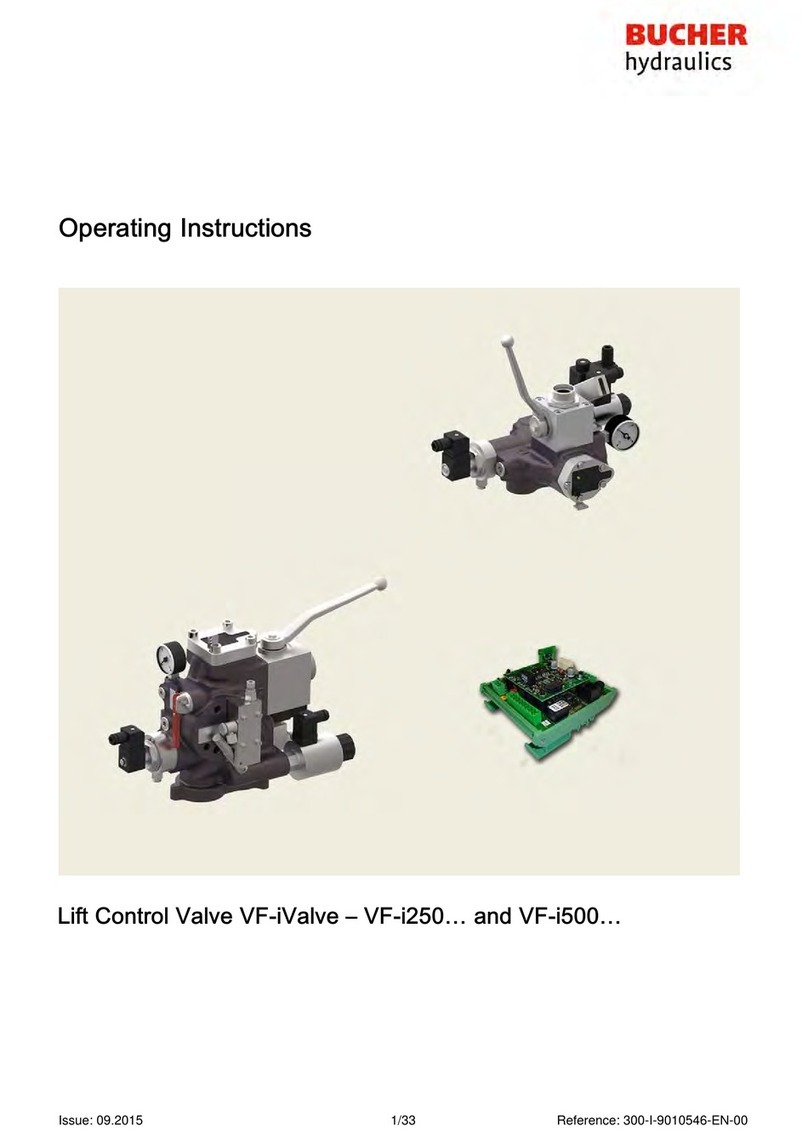
Bucher Hydraulics LRV-1 Installation manual

LRV-1 lift control valve
2/86 300-I-9010050-E-28/02.2012
Publisher
Bucher Hydraulics AG
Industriestrasse 15
CH-6345 Neuheim
Phone +41 41 757 03 33
Fax +41 41 757 05 00
Email[email protected]
Internet www.bucherhydraulics.com
E2012 by Bucher Hydraulics AG, CH-6345 Neuheim
All rights reserved. This documentation, in whole and/or in part, is protected by copyright. It may
not be reproduced, nor may it be stored, processed, replicated or distributed by electronic means,
without written permission from Bucher Hydraulics.
Data is provided for the purpose of product description only, and must not be construed as war
ranted characteristics in the legal sense. No assertion regarding either a particular property or the
fitness for a particular intended purpose can be derived or deduced from this information. The in
formation does not relieve users from the duty of conducting their own evaluations and tests.
Because the products are subject to continual improvement, we reserve the right to amend the
product specifications contained in this catalogue. The original language and legal terminology of
all Bucher Hydraulics documentation is exclusively German. Bucher Hydraulics cannot be held
liable for any possible errors in translation.

LRV-1 lift control valve
3/86
300-I-9010050-E-28/02.2012
Contents Page
1 General, product description 5
...................................................................
1.1 Target group 5
..........................................................................
1.2 Supplementary documents 5
..............................................................
1.3 Specialist terms 5
.......................................................................
1.4 Important notes 6
.......................................................................
1.4.1 Subassemblies 6
................................................................
1.4.2 Intended use 6
..................................................................
1.4.3 Conformity 7
....................................................................
1.5 Product identification 8
...................................................................
1.5.1 Nameplate 8
....................................................................
1.5.2 Test number 8
..................................................................
1.5.3 Model code 9
...................................................................
1.6 LRV‐1 lift control valve 10
.................................................................
1.6.1 Simplified hydraulic–electrical diagram 11
............................................
1.6.2 Electrical connection diagram 12
...................................................
1.6.3 Factory settings 13
...............................................................
1.6.4 Description of function 13
..........................................................
1.6.5 Technical data 16
................................................................
1.6.6 Pressure drop 18
.................................................................
1.7 DELCON electronic card 20
...............................................................
1.7.1 Factory settings 20
...............................................................
1.7.2 Description of function 21
..........................................................
1.7.3 Technical data 22
................................................................
1.7.4 Travel and switching diagram for normal travel distance 23
............................
1.7.5 Travel and switching diagram for short travel distances 24
.............................
1.8 NTA‐2 power supply unit 25
...............................................................
1.8.1 Description 25
...................................................................
1.8.2 Technical data 28
................................................................
1.8.3 Terminal assignments 29
..........................................................
1.9 IWK-1 feedback cable 31
..................................................................
1.10 Surroundings 31
.........................................................................
1.11 Emissions 31
............................................................................
2 Safety instructions 32
............................................................................
3 Operating controls and indicators 33
...............................................................
3.1 Emergency-lowering valve (EN81.2 art. 12.9) 34
.............................................
3.2 Display of the operating status 35
..........................................................
3.3 Miniterminal 35
...........................................................................
3.4 Handterminal 38
.........................................................................
3.5 Password 39
.............................................................................
3.6 WinDelta32 -PC program 43
..............................................................
4 Installation and commissioning 44
.................................................................
4.1 Installation 44
............................................................................

LRV-1 lift control valve
4/86 300-I-9010050-E-28/02.2012
4.2 Assembly 44
.............................................................................
4.2.1 Hose or pipe 44
..................................................................
4.2.2 Power supply unit 45
..............................................................
4.2.3 Wiring the power supply unit 46
....................................................
4.2.4 Electrical emergency-lowering 2x24 VDC 47
........................................
4.2.5 Electrical emergency-lowering 1x12 or 1x24 VDC (option) 48
........................
4.3 Commissioning/settings 49
................................................................
4.3.1 Checking the test numbers 49
......................................................
4.3.2 Checking the minimum static pressure 49
............................................
4.3.3 Bypass pressure setting 50
........................................................
4.3.4 Setting of the max. operating pressure (EN 81-2, art. 12.5.3) 53
........................
4.3.5 The demand/feedback response difference, SIU-1 54
.................................
4.3.6 Speed-monitoring in the unlocking zone of the door SIU-4 54
...........................
4.3.7 The inspection-travel speed setting 54
..............................................
4.3.8 Positioning the shaft switches for the deceleration distance 55
..........................
4.3.9 Setting the mechanical zero point 56
................................................
4.3.10 Pilot filters 57
....................................................................
4.3.11 Pipe rupture valve test 59
..........................................................
5 Operation 63
.................................................................................
5.1 Parameterisation with Handterminal 63
......................................................
5.2 Parameterisation with Miniterminal 64
.......................................................
5.3 Overview travel curve parameters 64
.......................................................
5.4 Overview control parameters (PID) 65
.......................................................
5.5 Description of parameters 65
..............................................................
5.5.1 Demand values menu 65
..........................................................
5.5.2 Options menu 67
.................................................................
5.5.3 Zero point /Hall sensor menu 71
...................................................
5.5.4 Information menu 72
.............................................................
5.6 Calculating the demand values for maximum speed 73
........................................
5.7 Faults /Fault-finding 74
...................................................................
5.7.1 Check list for fault correction 74
....................................................
5.7.2 Error messages 78
...............................................................
5.7.3 Warnings 80
.....................................................................
5.7.4 Informations 81
..................................................................
6 Maintenance 82
.............................................................................
6.1 Maintenance schedule 82
.................................................................
6.2 Hydraulic fluids 83
........................................................................
6.2.1 Jerky movement at low speed 83
...................................................
6.2.2 Mineral oils 83
...................................................................
6.2.3 Tested and approved hydraulic fluids with biodegradable characteristics 84
..............
6.2.4 Useful service life 85
..............................................................
6.3 Installation guide for DOWN pilot valve 86
...................................................

LRV-1 lift control valve 1 General, product description
5/86
300-I-9010050-E-28/02.2012
1 General, product description
This guide is an integral part of the product. It describes the product’s
safe use in all phases of operation and is valid for all model series that
are referred to.
1.1 Target group
SOperator
SInstaller
SService engineer
SRepair technician
1.2 Supplementary documents
Description Document
Lift Control Valve, Quick-Start Guide 300-P-9010169
1.3 Specialist terms
Term Definition
DELCON Electronic control card for LRV‐1 valve

LRV-1 lift control valve1 General, product description
6/86 300-I-9010050-E-28/02.2012
1.4 Important notes
1.4.1 Subassemblies
This guide differentiates between the following subassemblies:
LRV‐1 lift control valve
DELCON electronic control card
on NTA-2
NTA-2 power supply unit
1.4.2 Intended use
Lift control valve for operating hydraulically-driven passenger and goods
lifts.
The products must not be handled in any way by unauthorised persons.

LRV-1 lift control valve1 General, product description
8/86 300-I-9010050-E-28/02.2012
1.5 Product identification
1.5.1 Nameplate
12
67
8
9
34
5
LRV175-1 R175/K251/VN
120 / 150 l/min 21 / 45 bar
P min-max/adj 7-63 / 55 bar
...
10
11
1 Valve type = LRV 175
2 Flow ring = R175
3 Spool = K251
4 Manual emergency-lowering valve with
preload = VN
5 Flow rate UP = 120l/min
6 Flow rate DOWN = 150l/min
7 Minimum static pressure (empty car)
= 21bar
8 Maximum static pressure (full car)
= 45bar
9 Setting range = 7…63bar
10 Set for maximum working pressure
= 55bar
11 Customer specific data
1.5.2 Test number
2
1
Legend 1
2
Test number
Nameplate

LRV-1 lift control valve 1 General, product description
9/86
300-I-9010050-E-28/02.2012
1.5.3 Model code
D0/MP/
EN00
/VN
K 251 /-
LRV 175-1 /
Valve type/size
= LRV 175-1
= LRV 350-1
= LRV 700-1
Flow range: flow rate/type
LRV 175-1 15…45l/min = R 45
46…90l/min = R 90
91…175l/min = R 175
176…250l/min = R 250
LRV 350-1 150…250l/min = R 250
251…350l/min = R 350
351…500l/min = R 500
LRV 700-1 400…700l/min = R 700
701…1000l/min = R 1000
Spool: flow rate/type
LRV 175-1 15…90l/min = K 91
91…250l/min = K 251
LRV 350-1 150…500l/min = K 501
LRV 700-1 400…1000l/min = K 1001
Manual emergency-lowering valve
Emergency-lowering valve with preload = VN
Emergency-lowering valve without preload = SN
Electrical emergency-lowering valve
without electrical emergency-lowering valve = EN 00
with DC solenoid 12V = EN 12
with DC solenoid 24V = EN 24*
* further option: via NTA‐2 with 2x24V batteries,
⇒page 29, chapter 1.8.3 and page 47, chapter 4.2.4
Test port
without test nipple (female thread G½”) = OP
with test nipple (DIN 16271) = MP
DELCON type
without DELCON = D0
with DELCON = D1
R 175

LRV-1 lift control valve1 General, product description
10/86 300-I-9010050-E-28/02.2012
1.6 LRV‐1 lift control valve
Legend 1
2
3
4
5
6
7
8
Maximum-pressure setscrew
Bypass-pressure setscrew
Lowering-speed limiter (valve
size 700 only)
Pressure-relief valve
Pilot filter
Test port, G½
Pressure gauge
Pressure gauge shut-off screw
(valve sizes 175 and 350)/
Pressure gauge shut-off valve
(valve size 700)
9
10
11
12
13
14
15
16
17
18
20
21
Air-bleed screw
Hall sensor
Main filter
Flow-rate measuring system
Emergency-lowering valve
DOWN spool
Check valve
UP spool
UP damping jet
DOWN damping jet
Pipe rupture valve
Ball valve
P
T
Z
Z1
Z2
Z3
Pump port
Tank port
Cylinder port
Pressure switch port
Hand pump port
A
B
C
D
DELCON
NTA‐2
LRV‐1
Control cabinet (customer's)

LRV-1 lift control valve 1 General, product description
11/86
300-I-9010050-E-28/02.2012
1.6.1 Simplified hydraulic–electrical diagram
A
B
C
D
4
6
7
8
10
11
12
13
14
15
16
20
21
22
23
24
M
PT
Z
Z1
Z2
Z3
K1
K2
K3
K4
K5
K6
K7
K8
25
R1
R1’
R2
R2’
M
22a
Legend 4
6
7
8
10
11
12
13
Pressure-relief valve
Test point, G½
Pressure gauge
Pressure gauge shut-off
screw/ valve
Feedback sensor
(non-contacting)
Main filter
Flow-rate measuring system
Emergency-lowering valve
14
15
16
20
21
22
22a
23
24
25
DOWN spool
Check valve
UP spool
Pipe-rupture valve
Ball valve
Elec. emergency lowering (opt.)
Speed set. elec. emerg. low.
Pressure switch
Hand pump
Relevelling (optional)
P
T
Z
Z1
Z2
Z3
Pump port
Tank port
Cylinder port
Pressure switch port
Hand pump port
R1
R2
A
B
C
D
to EN81-2, 12.4.1/12.4.2
DELCON
NTA‐2
LRV‐1
Control cabinet (customer's)

LRV-1 lift control valve1 General, product description
12/86 300-I-9010050-E-28/02.2012
1.6.2 Electrical connection diagram
GND
YE
WH
GN
BN
A
B
C
D
22
26a
26b 4 x 12 V = 48 V
2 x 24 V = 48 V
L1, L2, L3, PE
300-1.10009306
RN
RN
RN
Legend A
B
C
D
BN
GN
WH
YE
DELCON
NTA‐2
LRV‐1
Control cabinet (customer's)
brown
green
white
yellow
22
26a/b
R1
R2
Electrical emergency-lowering
12 or 24 VDC (option)
⇒page48, chapter4.2.5
Electrical emergency-lowering
2 x 24 VDC
⇒page47, chapter4.2.4
to EN81-2, 12.4.1/12.4.2

LRV-1 lift control valve 1 General, product description
13/86
300-I-9010050-E-28/02.2012
1.6.3 Factory settings
All valves are factory-set to the values for the particular installation and
then tested.
SPressure-relief valve set to the maximum working pressure
SBypass pressure as per the calculated minimum static pressure
SEmergency-lowering valve set to 5…10% of maximum DOWN
speed
SMechanical zero point of the feedback sensor
1.6.4 Description of function
The lift control valve can be subdivided into 3 main functions.
1. UP section / pressure-relief valve
4
1
16
SInitial position:
UP spool (16) is open in the 0 position; pump flow goes directly to
tank
SUp travel / acceleration:
UP spool (16) is progressively closed by the electro-proportional
valve (UP solenoid); this results in smooth acceleration of the lift up
to maximum speed
SDeceleration:
UP spool (16) is progressively opened by the electro-proportional
valve (UP solenoid); this results in smooth deceleration of the lift to
standstill
SOverload:
pressure-relief valve (4) and UP spool (16) open when the maximum
working pressure set with screw (1) is reached

LRV-1 lift control valve1 General, product description
14/86 300-I-9010050-E-28/02.2012
2. DOWN section / Emergency-lowering valve
13
14
The down section is constructed in a similar way to the up section.
SInitial position:
DOWN spool (14) is closed leak-free in the 0 position
SDown travel / acceleration:
DOWN spool (14) is progressively opened by the electro-proportional
valve (DOWN solenoid); this results in smooth acceleration
SDeceleration:
DOWN spool (14) is progressively closed by the electro-proportional
valve (DOWN solenoid); this results in smooth deceleration of the lift
to standstill
SPower failure/ evacuation:
With the electrical emergency-lowering valve (optional), the car can
be lowered using DC voltage (⇒page48, chapter4.2.5)
SThe car can be lowered slowly with the manual emergency-lowering
valve (13)

LRV-1 lift control valve 1 General, product description
15/86
300-I-9010050-E-28/02.2012
3. Flow-rate measuring system
10
12
SThe oil flows through the flow meter (12) in both the up and down
directions
SThe baffle-disc is displaced axially as a function of the flow rate
SThis axial displacement is converted by a non-contacting feedback
transducer (10) into an electrical DC signal (the feedback signal),
which is then sent to the DELCON.
SThe output signal (the feedback) is proportional to the flow rate
SThe controller in the DELCON works to match the feedback value to
the demand signal

LRV-1 lift control valve1 General, product description
16/86 300-I-9010050-E-28/02.2012
1.6.5 Technical data
300-7-10015573
H*
R*
L*
a
A
Legend
View: valve sizes 175 and
350
1
2
3
4
Flow-rate measuring system
Pressure-relief valve
DOWN solenoid
UP solenoid
5
6
7
a
Orientation of Z-port
Pressure gauge shut-off screw
(valve sizes 175 and 350)/
Pressure gauge shut-off valve
(valve size 700)
Test number (embossed)
View from below
Z1
Z2
Z3
P
T
Z
Pressure switch port
Hand pump port
Pump port
Tank port
Cylinder port
H*
L*
R*
Orientation of Z-port
(specify when ordering!)
rear (standard)
left
right

LRV-1 lift control valve 1 General, product description
17/86
300-I-9010050-E-28/02.2012
Type Ports Ports Weight Max. press.
Z, T, P Z1, Z2, Z3 [kg] [bar]
LRV 175-1 G1 G¼ 8 80
LRV 350-1 G1½ G¼ 11 80
LRV 700-1 G2, G2½, G2 G¼, G¼, G3/822.5 67
Type Dimensions [mm]
b c d e k L m n p1 p2 s1 s2 t v1 v2
LRV 175-1 199 325 182 208 50 47 55 175 21 27 75 15 M8 9 23
LRV 350-1 219 355 205 208 65 48 63 200 35 38 85 25 M10 14 28
LRV 700-1 297 428 255 225 80 87 83 265 48 56 124 41 M10 30 30
SThe permissible temperature range is determined by the permissible
viscosity range of 20…500cSt.
SIndependent of the viscosity the temperature must not fall below 0°C
and must not exceed 70°C.
SFor detailed information, ⇒page83, chapter6.2

LRV-1 lift control valve1 General, product description
18/86 300-I-9010050-E-28/02.2012
1.6.6 Pressure drop
R 90 R 175 R 250R 45
15
12.5
10
7.5
5
2.5
20
50
90
100
180
250
200
150
Spool K 91
Spool K 251
A
B
UP (P-Z)
DOWN (Z-T)
LRV 175-1
Flow ring (R)
R 350 R 500R 250
15
12.5
10
7.5
5
2.5
150
175
200
225
250
275
300
325
350
375
400
425
450
475
500
Flow ring (R)
LRV 350-1
Spool K 501
A
B
DOWN (Z-T)
UP (P-Z)
Legend A
B
Pressure drop [bar] min. required dynamic pressure
Flow rate Q [l/min.]
500 cSt (Motorex Corex HLP 46 at approx. 2°C)
300 cSt (Motorex Corex HLP 46 at approx. 7.5°C)
75 cSt (Motorex Corex HLP 46 at approx. 30°C)

LRV-1 lift control valve 1 General, product description
19/86
300-I-9010050-E-28/02.2012
R 1000R 700
15
12.5
10
7.5
5
2.5
400
450
500
550
600
650
700
750
800
850
900
950
1000
LRV 700-1
A
B
Spool K 1001
Flow ring (R)
DOWN (Z-T)
UP (P-Z)
Legend A
B
Pressure drop [bar] min. required dynamic pressure
Flow rate Q [l/min.]
500 cSt (Motorex Corex HLP 46 at approx. 2°C)
300 cSt (Motorex Corex HLP 46 at approx. 7.5°C)
75 cSt (Motorex Corex HLP 46 at approx. 30°C)

LRV-1 lift control valve1 General, product description
20/86 300-I-9010050-E-28/02.2012
1.7 DELCON electronic card
The DELCON controls the oil flow - and therefore the lift's travel profile -
in accordance with a preset curve.
NOTICE!
Electrostatic discharge (ESD)
The DELCON can be damaged by incorrect handling.
Always keep the DELCON in its ESD protective bag and
only hold it by the front panel.
6
1
2
3
54
7
Legend 1
2
3
4
5
6
7
RESET button (restarts the program in the
DELCON electronic card)
Nameplate
Label with serial number
Description of LED functions
RS-232 port
LED
Label with test number and demand values
1.7.1 Factory settings
SMaximum UP and DOWN speeds
SSlow speed set to 5…10% of maximum speed
SAcceleration/deceleration set to mid-range value
SInspection travel speed set to 50% of maximum speed
Table of contents
Other Bucher Hydraulics Control Unit manuals
Popular Control Unit manuals by other brands

Monacor
Monacor PA ATT-325ST manual

Telit Wireless Solutions
Telit Wireless Solutions SL869T3-I Product user guide

Orbinox
Orbinox FAGERBERG EK Installation, operation & maintenance manual

nvent
nvent ERIFLEX UDJ125A manual

Littfinski Daten Technik
Littfinski Daten Technik Digital-Professional Series Assembly instruction

Advantech
Advantech AMAX-4800 Series user manual

CommScope
CommScope ATSBT-4G Series instruction sheet

Red Jacket
Red Jacket 880-051-1 Installation and owner's manual

RS Scene Automation
RS Scene Automation AC1-ZW installation guide

FIRELINX
FIRELINX CM-64 user manual

Force 10
Force 10 XFP Installing and Removing

Daikin
Daikin ACZ Installation and maintenance manual