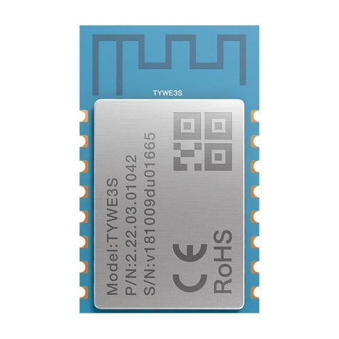
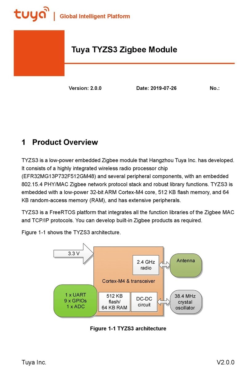
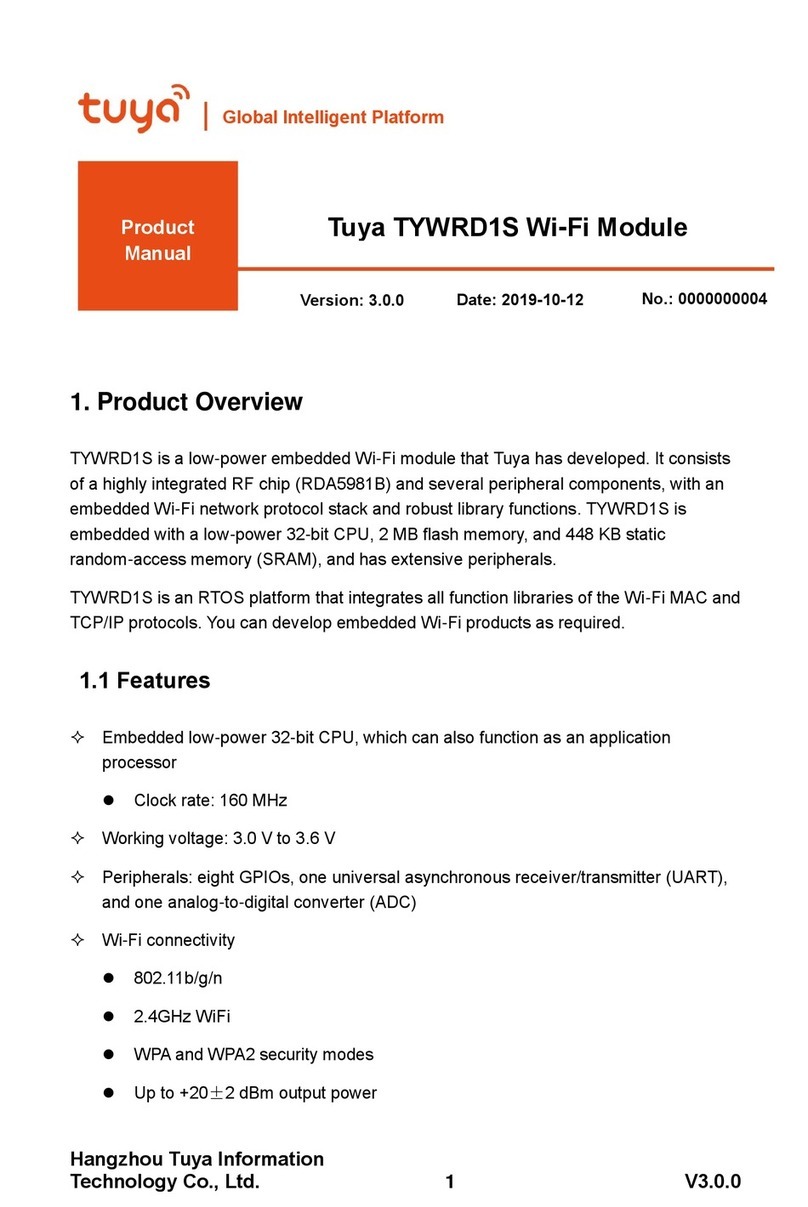
TUYA TYBT4L User manual

TYBT4L V1.0.0 UserManual
Version1.0.0
1
BLE module introduction–TYBT4L
Contents
1. Product Overview .........................................................................................................................2
1.1 Features...............................................................................................................................2
1.2 Major Application Fields ....................................................................................................3
2. Module Interfaces .........................................................................................................................3
2.1 Dimensions and Footprint...................................................................................................3
2.2 Pin definition ......................................................................................................................4
3. Electrical Characteristics ..............................................................................................................6
3.1 Absolute Electrical Characteristics .....................................................................................6
3.2 Electrical Conditions...........................................................................................................6
3.3 Power Consumption in Operating Mode..........................................................................7
4. RF Features...................................................................................................................................7
4.1 Basic RF Features ...............................................................................................................7
4.2 RF Output Power ................................................................................................................7
4.3 RF RX Sensitivity...............................................................................................................8
5.Antenna Information......................................................................................................................8
5.1 Antenna Types ....................................................................................................................8
5.2 Antenna Interference Reduction .........................................................................................8
6.Packaging information and production instruction ......................................................................10
6.1 Mechanical Dimensions and Size of the Back Pad ...........................................................10
6.2 Production Instructions .....................................................................................................10

TYBT4L V1.0.0 UserManual
Version1.0.0
2
1. Product Overview
TYBT4L is a low power-consuming built-in Bluetooth module developed by Hangzhou Tuya
Information Technology Co., Ltd. It consists of a highly integrated Bluetooth chip (TLSR8267)
and several peripheral electrical circuits, with a built-in Bluetooth network communication
protocol stack and robust library functions. TYBT4L also contains a low power-consuming 32-bit
MCU, a BLE, a 512 KB flash, a 16 KB SRAM, and nine multiplex I/O ports.
1.1 Features
Built-in low power-consuming 32-bit CPU, which can also be used as an application
processor
Basic frequency: 48 MHz supported
Working voltage: 1.9 V to 3.6 V
Peripherals: one I2C interface, five PWMs, and one UART
BLE RF features
Compatible with BLE 4.2
RF data rate: up to 1Mbit/s
RX sensitivity: –92 dBm
Built-in AES encryption for hardware
Onboard PCB antenna
Working temperature: –20°C to +105°C
1.2 Major Application Fields
Intelligent LED
Intelligent home

TYBT4L V1.0.0 UserManual
Version1.0.0
3
Intelligent low-power sensors
2. Module Interfaces
2.1 Dimensions and Footprint
TYBT4L provides two rows of pins with the distance of 2.0 mm between every two pins.
TYBT4L dimensions: 16 mm (W) x 24 mm (L) (see figure 2.1)
2.2 Pin definition
Table 2.1 describes the interface pins.
Table 2.1 TYBT4L interface pins
No.
Symbol
I/O
Type
Functions
1
RST
I
Module reset pin
2
ADC
I
External analog input
3
NC
/
NC interface, which is not connected
4
SDA
I/O
Pin for the data line of the I2C interface, which
must be connected to a 4.7 kΩ pull-up resistor.
This pin can also be used as the common I/O
interface.
5
B
I/O
Common I/O interface, which can be used for
PWM output of the LED driver. It controls the blue
LED by default.
6
G
I/O
Common I/O interface, which can be used for
PWM output of the LED driver. It controls the
green LED by default.

TYBT4L V1.0.0 UserManual
Version1.0.0
4
7
WW
I/O
Common I/O interface, which can be used for
PWM output of the LED driver. It controls the
warm white LED by default.
8
3.3 V
P
Module power supply input pin
9
GND
P
Module power supply reference ground pin
10
PA7
I/O
Used as the common I/O interface
11
SWS
I/O
Bluetooth chip programming pin
12
SCL
I/O
Pin for the clock line of the I2C interface, which
must be connected to a 4.7 kΩ pull-up resistor.
This pin can also be used as the common I/O
interface.
13
R
I/O
Common I/O interface, which can be used for
PWM output of the LED driver. It controls the red
LED by default.
14
CW
I/O
Common I/O interface, which can be used for
PWM output of the LED driver. It controls the cold
white LED by default.
15
RX
I/O
Serial port TX pin, used as the common I/O
interface
16
TX
I/O
Serial port TX pin, used as the common I/O
interface
Note: P indicates power-supply pins, and I/O indicates input/output pins.
The SWS pin is used only for programming of module firmware.
The I2C pin does not provide a pull-up resistor. It must be connected to an external pull-up
resistor.
When the WW pin is used for PWM output, its polarity is opposite to that of the R, G, B,
and CW pins used for PWM output.
If you have special requirements for the light color controlled by PWM output, contact our
business manager.
3. Electrical Characteristics
3.1 Absolute Electrical Characteristics
Table 3 .1Absolute electrical characteristics
PARAMETERS
DESCRIPTI
ON
MIN
MAX
UNIT
Ts
Storage
temperature
-40
125
℃
VCC
Power supply
voltage
-0.3
3.9
V
Static electricity voltage
(human model)
TAMB-25℃
-
2
KV
Static electricity voltage
(machine model)
TAMB-25℃
-
0.5
KV
3.2 Electrical Conditions

TYBT4L V1.0.0 UserManual
Version1.0.0
5
Table 3.2Normal electrical conditions
Paramet
ers
Description
Min
Typ
Max
Unit
Ta
Working
temperature
–20
-
105
°C
VCC
Working voltage
1.9
3.3
3.6
V
VIL
I/O low-level input
–0.3
-
VCC*0.3
V
VIH
I/O high-level input
VCC*0.7
-
VCC
V
VOL
I/O low-level output
VSS
-
0.3
V
VoH
I/O high-level
output
VCC–0.3
-
VCC
V
3.3 Power Consumption in Operating Mode
Table 3.3 TX power consumption during constant emission
Symbol
Condition
Typical Value
Unit
Itx
Constant emission,
with 0 dBm output
power
15
mA
Irx
Constant receiving
12
mA
IDC
Mesh connected
27
mA
Ideepsleep
Sleep mode
18
uA
4. RF Features
4.1 Basic RF Features
Table 4.1 Basic RF features
Parameter
Description
Frequency band
2.4 GHz ISM band

TYBT4L V1.0.0 UserManual
Version1.0.0
6
Radio standard
BLE 4.2
Data transmitting
rate
1 Mbit/s
Antenna type
Onboard PCB antenna
4.2 RF Output Power
Table 4.2 TX power during constant emission
PARAMETERS
MIN
TYPICA
L
MA
X
UNI
T
RF output power - 4.73 -
dBm
6dB modulation signal bandwidth (1 M)
-
709
-
KHz
4.3 RF RX Sensitivity
Table 4.3 RX sensitivity
Parameter
Min
Typ
Max
Unit
RX sensitivity
1Mbit/s
-93
-92
-90
dBm
Frequency offset error 1Mbit/s -300 - +300 KHz
Co-channel interference suppression - - -7 - dB
5.Antenna Information
5.1 Antenna Types
TYBT4L has an on-board PCB antenna for BLE .
5.2 Antenna Interference Reduction
To ensure optimal RF performance, it is recommended that there be a space of at least 15
mm between the module antenna and other metal parts. TYBT4L is attached to the PCB with
other components using the SMT. In this case, the routing position and method of the PCB
antenna directly affect the RF performance. The following figures show the recommended and not
recommended routing positions.
As shown in Figure 5.1, if most of the antenna is outside the PCB frame, solutions 1 and
2 are recommended. The antenna is placed outside the PCB frame or the PCB is carved to reserve
an area for the antenna. By using these two solutions, the performance of TYBT4L is almost the
same as that of the module when being tested independently. If the antenna must be routed on the
PCB due to restrictions, solution 3 is recommended.
The antenna is placed inside the PCB frame and no copper or wire is routed near the
antenna. If this solution is used, the performance is reduced by about 1–2 dBm. It is not
recommended that solution 4 be used, in which the antenna is placed inside the PCB and copper
and other wires are routed under the antenna. In this solution, the RF signal has significantly
attenuation.

TYBT4L V1.0.0 UserManual
Version1.0.0
7
6.Packaging information and production instruction
6.1 Mechanical Dimensions and Size of the Back Pad
Figure 6.1 TYBT4L size diagram

TYBT4L V1.0.0 UserManual
Version1.0.0
8
6.2 Production Instructions
Storage conditions of a delivered module are as follows:
1.The anti-moisture bag must be placed in an environment where the temperature is under
30°C and the relative humidity is under 85%.
2.The shelf life of a dry-packaged product is six months from the date when the product is
packaged and sealed.
Precautions:
1.Throughout the production process, each involved operator must wear an electrostatic
ring.
2.During the operation, strictly protect the module from water and strains.

FCC Statement
Any Changes or modifications not expressly approved by the party responsible for compliance could
void the user’s authority tooperate the equipment.
This device complies with part 15 of the FCC Rules. Operation is subject to the following
two conditions:
(1) This device may not cause harmful interference, and
(2) This device must accept any interference received, including interference that may cause
undesired operation.
FCC Radiation Exposure Statement:
This equipment complies with FCC radiation exposure limits set forth for an uncontrolled
environment .This equipment should be installed and operated with minimum distance 20cm
between the radiator& your body.
FCC Label Instructions:
The outside of final products that contains this module device must display a label referring to the
enclosed module. This exterior label can use wording such as: “Contains Transmitter Module
FCC ID: 2ANDL-TYBT4L”,or “Contains FCC ID: 2ANDL-TYBT4L”,
Any similar wording that expresses the same meaning may be used.
Regulatory Module Integration Instructions
This device complies with part 15.247 of the FCC Rules.
The OEM integrator has to be aware not to provide information to the end user regarding how to install or
remove this RF module in the user’s manual of the end product which integrates this module.
The antenna is PCB Antenna and maximum gain is 2.0dBi .
This module has been granted modular approval for mobile applications. OEM integrators
for host products may use the module in their final products without additional FCC certification if they
meet the following conditions. Otherwise, additional FCC approvals must be obtained.
The host product with the module installed must be evaluated for simultaneous
transmission requirements.
The user’s manual for the host product must clearly indicate the operating requirements
and conditions that must be observed to ensure compliance with current FCC RF exposure guidelines.
To comply with FCC regulations limiting both maximum RF output power and human
exposure to RF radiation, use this module only with the included onboard antenna.
The final host / module combination may also need to be evaluated against the FCC Part 15B
criteria for unintentional radiators in order to be properly authorized for operation as a Part 15
digital device.
Table of contents
Other TUYA Control Unit manuals
Popular Control Unit manuals by other brands

Aaeon
Aaeon PER-C38L Quick installation guide

CALEFFI
CALEFFI ThermoSetter 1164 Series Installation, commissioning and servicing instructions

AMX
AMX RDM-FDB Wiring diagram

NEONODE
NEONODE NNAMC2090PCEV Get started

Dungs
Dungs DMK 5040 Operation and assembly instructions

Gemalto
Gemalto Cinterion EMS31-US Hardware Interface Overview