Elk ELK-M1XSLC User manual

L669 Rev. A 1/25/2016 Printed in USA
APPLICATION:
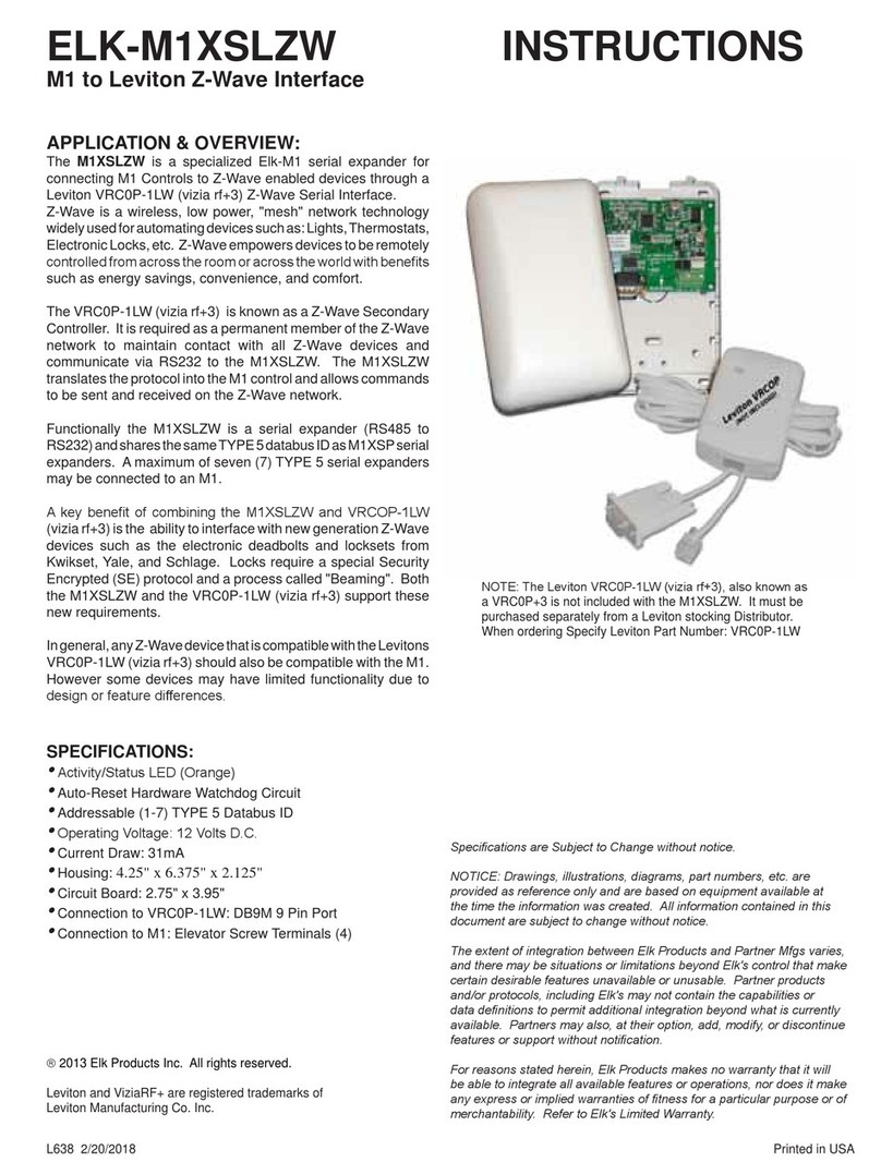
The ELK-M1XSLC Interface Kit has been enhanced
to support Lutron's Homeworks and Caséta products.
Interfacing M1 Control to Lutron allows intelligent control
of devices in response to security system actions or
conditions. The most typical integration devices supported
are:Lights, Shades, and Keypad controllers. The level
of integration is dependent on which type and model of
Lutron devices being implemented. Some models of
Thermostats are also supported.
ELK-M1XSLU SPECIFICATIONS:
•Connects to the ELK-M1 Keypad Databus
•Addressable as a TYPE 5 Databus (ID 1-7)
•Operating Voltage: 12 Volts DC Supplied from M1
•Current Draw: 31mA
•Activity/Status LED (Orange)
•Auto-Reset Hardware Watchdog Circuit
•Housing Dimensions: 4.25" x 6.375" x 2.125"
•Circuit Board: 2.75" x 3.95"
•Connects to IP232 via RS232 and null modem (Incl.)
•Connects to M1 via 4 screw terminals
ELK-IP232 SPECIFICATIONS:
• Converts RS232 Serial to IP for connection to the IP
port on Lutron's QS or Smartbridge Pro Interfaces
• LED Indicators for Power, Link, and Data
• Operating Voltage: 12 Volts D.C.
Supplied from ELK-P1216 Power Supply (Incl)
• Current Draw: 135 mA
• Dimensions: 3.85” L x 1.7” W x 0.93” D
ELK-M1XSLC
M1 Interface kit for Lutron
Homeworks QS or Caséta Line
HOMEWORKS®QS
INSTRUCTIONS
Specications are Subject to Change without notice.
NOTICE: Drawings, illustrations, diagrams, part numbers, etc. are provid-
ed as reference only and are based on equipment available at the time
the information was created. All information contained in this document
are subject to change without notice.
The extent of integration between Elk Products and Partner Mfgs varies,
and there may be situations or limitations beyond Elk's control that make
certain desirable features unavailable or unusable. Partner products and/
or protocols, including Elk's may not contain the capabilities or data de-
nitions to permit additional integration beyond what is currently available.
Partners may also, at their option, add, modify, or discontinue features or
support without notication.
For reasons stated herein, Elk Products makes no warranty that it will
be able to integrate all available features or operations, nor does it make
any express or implied warranties of tness for a particular purpose or of
merchantability. Refer to Elk's Limited Warranty.
2017 Elk Products Inc. All rights reserved.
Lutron, Homeworks, QS, Caséta Wireless, and Smartbridge Pro are
registered trademarks of Lutron Electronics Co., Inc.
PO Box 100
3266 US Hwy 70 West
Hildebran, NC 28637
828-397-4200 828-397-4415 Fax
http://www.elkproducts.com
To support integration with Homeworks
QS, a rmware update to the M1XSLU is
required. See page 4 for details.
!

Page 2 M1XSLC Installation Manual - LUTRON HOMEWORKS QS
Lutron Homeworks®QS
The following components will be needed to integrate Elk to Lutron Homeworks QS.
Part Number & Description
ELK-M1 or M1EZ8 Control
ELK-M1XSLCv2 Kit
Contents of kit:
ELK-M1XSLU M1 to Lutron serial interface, UPDATED with SPECIAL FIRMWARE VERSION 80.0.6 (see page 4)
ELK-IP232 Serial to IP Converter (Firmware version 1.0.18 and later ***)
9 Pin Serial ribbon cable
9 Pin Null Modem adapter
ELK-P1216 Plug-in 12VDC Power Supply
ELKRP Remote Programming Software. This can be downloaded from Elk Website www.elkproducts.com
ELK-IP232 Utility Software. This can be downloaded from Elk Website www.elkproducts.com
Lutron QS Processor w/plug-in Power Pack
Lutron QS System Devices
Lutron QS Design Software
Please refer to the following pages for the steps and requirements of interfacing.
*** The ELK-IP232 contained in this kit is pre-loaded with the most recent rmware version (v1.0.18 or later). If you already
own an older IP232 and attempt to use it instead of the one supplied In this kit, the older unit will most likely need to be
rmware update to the most recent version (v1.0.18 or later) prior to use.
Overview: Lutron Homeworks QS devices communicate through a central interface, the Lutron Homeworks QS Procoessor. Supported
devices include lights, shades and thermostats. The ELK-M1XSLU Lutron Interface handles the protocol conversion from ELK to
Lutron and the ELK-IP232 creates the IP connectivity with the Lutron QS Processor.
Lutron Homeworks QS Designer Software: This software available from Lutron is REQUIRED for third party
integration. It is not possible to integrate with the Homeworks QS system unless it was setup and programmed by the
QS Designer software! Lutron Certication training may be required to obtain this sofware! This is restriction imposed
by Lutron, not Elk.
Integration Capacity: Each HomeWorks QS processor can support up to 100 hardwired and up to 100 wireless
devices in the Homeworks QS line. However, this does not mean that the Device ID numbers are restricted to 1-200.
On the contrary, with installation it will be quite common to nd active Devices with ID numbers higher than 200. The
reason is that not only does each repeater, dimmer, switch, tabletop controller, thermostat, etc. counts as a device, but
non-hardware entities such as rooms, oors, etc. are also assigned ID numbers, even though they are not physical
controllable active devices. Also, devices that are connected directly to a load (dimmers, switches, etc.) may be
assigned multiple devices IDs for both the load (zone) and the button (device). M1 (ElkRP) Lighting Device numbers
stop at 255. This means that M1 cannot control or communicate with any physical active device that has an ID
beyond 255. But there is a workable solution for this issue. The Lutron Homeworks QS software has a menu option
which allows manual re-numbering of Device IDs. The solution is to identify any active physical Device IDs beyond
255, and then use the programming option to change or swap them with lower Device IDs currently assigned to non-
hardware entities. In other words, arrange the network so that numbers above 255 are assigned to rooms, oors,
etc., and reserve the numbers 255 and lower for active physical Devices.
Important: Do not attempt to integrate with Lutron Homeworks using any of Elk's other "standard" serial interface modules. ONLY
the ELK-M1XSLC Kit provides the hardware and software for near plug-and-play integration with Lutron Homeworks.
PLEASE READ THIS PAGE FIRST!
LUTRON HOMEWORKS®QS

M1XSLC Installation Manual - LUTRON HOMEWORKS QS Page 3
LUTRON HOMEWORKS QS
Please setup the Lutron equipment and devices and have them all working before proceeding.
2.1 Turn off the power to all equipment before making any wiring connections.
2.2 Wire the M1XSLU to the M1's RS485 data bus. Please follow the recommendations in the M1 Installation book and this manual
for wiring the 4 conductors of the data bus (+12V, A, B, and Neg) to the terminals on the M1XSLU. You should never attach
more than 2 homerun cables directly to the M1 Control! The preferred way to connect multiple bus devices to M1 is to either
daisy chain connect them along each homerun wire, or add a data bus hub device (Elk M1DBH or M1DBHR) in the panel that
will support connection of mulitple homerun cables.
2.3 Wire the IP232 to the M1XSLU using the supplied DB9F to DB9M Serial ribbon cable and DB9M to DB9F Null Modem adapter.
DO NOT use an extension or attempt to make this cord any longer!
2.4 Wire the IP232 to the Lutron Homeworks QS Processor using a CAT5 or CAT6 network cable (not supplied). The IP232 converts
the serial topology of the M1XSLU into Ethernet (IP) topology allowing integration over IP to the Lutron Homeworks QS Processor.
2.5 Set the data bus address DIP switches on the M1XSLU to a value between 1 and 7 (see Table 1). Be sure the selected address
is not already being used by another Elk serial expander (type 5) device. Each switch has an OFF and On position (binary value
0 or 1). The combination of these switches represents a decimal value between 0 (all Off) and 15 (all On).
2.6 Wire the Lutron QS Processor to the LAN using a CAT5 or CAT6 network cable (not supplied). Power the Lutron device using
it's appropriate power supply.
2.7 The IP232 will be powered by the supplied P1216 plug-in AC to DC power supply. Connect power supply to barrel connector
on IP232.
2.8 If all wired connections are complete and secure it is now OK to apply power to the M1 Control which also supplies the power
to the M1XSLU.
2.9 Perform a M1 Bus Module Enrollment to enroll the M1XSLU into the M1 Control. This can be done from a M1 Keypad or the
ElkRP Software. From a Keypad access the Installer level programming and select Menu 01-Bus Module Enrollment. Press
the right arrow key to start the enrollment. When complete press the right arrow (edit) key to view the results. NOTE: The ELK-
M1XSLU shares the same bus type as other serial expanders and will display as a "SerialPExpdr T5" followed by a specic
address (Addr) number. Verify the address displayed matches the address selected in step 2.5 above.
Should it ever be necessary to replace a ELK-M1XSLU; set the replacement unit to the same address as the old unit and perform
the enrollment process. To permanently remove any data bus device perform the enrollment process AFTER disconnecting the
device. This will help avoid a "missing device" trouble condition.
2 - Equipment Setup
TABLE 2: Diagnostic LED Indicator
Slow blink (1/2 sec.) = Normal communication with M1.
Rapid flicker = Discovery Mode. The M1XSLU is synchronizing to collect current device data. This is automatically
performed upon reboot or power up.
No blink = No communication with M1. Check the wiring with the M1 and that the device has power.
TABLE 1: Data Bus Address Switch Settings
ON
1 2 3 4
ON
1 2 3 4
ON
1 2 3 4
ON
1 2 3 4
Address 1
ON
1 2 3 4
ON
1 2 3 4
ON
1 2 3 4
Address 2 Address 3 Address 4 Address 5 Address 6 Address 7 LEGEND
ON
OFF
Data Bus Terminating Jumper JP1 – This is engages a 120 Ohm resistor for terminating the M1 RS-485 Data Bus. See Data bus wiring instructions before use.
For Data Bus Type 5 Devices (Serial Expanders) the only valid Addresses are 1 thru 7 and therefore the maximum number of Type 5 Devices is 7.

M1XSLC Installation Manual - LUTRON HOMEWORKS QS
Page 4
LUTRON HOMEWORKS QS
Procedures for Updating the M1XSLU rmware
a. Connect a 9 pin serial cable or USB to serial adapter from the Computer to the 9 Pin RS232 Connector on the M1
Control. If you happen to have a M1XEP Ethernet module installed on the control, it may also be used for updating.
b. Using ElkRP, open the account belonging to this control and establish a connection from the Connection menu.
c. Use the “Receive All” option from the Send/Rcv menu to retrieve the very latest copy of all the data stored in the control.
d. Save the account information.
e. Click on the “Send/Rcv” menu/icon along the top of the PC screen, then click either “Update or Verify Firmware” OR
“Enroll/Update Control and Devices”
f. On the next screen you must choose the device to be updated.
g. The Update screen will display the current Firmware, Hardware, and Bootware version, along with pull down selection to
select the update le(s) that are available.
h. Choosing an update:
1. Bootware Update: This step may be skipped unless specically required by the rmware update. Please refer to
the release notes for the current update.
Use the scroll arrow to select the Bootware le for this update. Based on the hardware revision there may be more
than 1 le. Just make sure the le selected contains the word “BOOT” and the current (latest) version number.
Select Update. Once the bootware update is complete you may proceed to the Firmware Update. The control may
disconnect after the bootloader is nished. If so, just re-connect and continue on with the Firmware Update.
2. Firmware Update:
Use the scroll arrow to select the appropriate Firmware le for this update. Based on the hardware revision there
may be more than 1 le. Just make sure that the le selected contains the current (latest) version number.
i. Select Update. (In some instances the Update button may be labeled “Continue”).
2.10 IMPORTANT! THE ELK-M1XSLU MUST BE UPDATED TO SPECIAL FIRMWARE VERSION 80.0.6 FOR COMPATIBILITY
WITH LUTRON HOMEWORKS QS. This special rmware version can be downloaded from the support section of our website,
www.elkproducts.com.

M1XSLC Installation Manual - LUTRON HOMEWORKS QS Page 5
LUTRON HOMEWORKS QS
Download and install the IP232 Conguration PC software utility from the ELK website (www.elkproducts.com). A copy of the IP232
instructions is packed with the M1XSLC kit with steps for defaulting, resetting, or updating the IP232 rmware if needed.
3.1 Be sure the IP232 is connected to the local area network and is powered by the P1216 plug-in power supply.
3.2 Launch the Conguration Utility and click ‘Search’ to nd the IP232 on the customer's local network. The Device Name (blank),
MAC Address, and IP Address should appear in the display.
The IP232 is factory set for DHCP (dynamic) mode whereby it expects to be assigned a non-permanent IP Address from the
client's router. DHCP makes it easy to add new devices to a network, however that address may change at some future time.
The IP232 can be also assigned to a permanent or STATIC Address. For purposes of interfacing with Lutron the IP232 does
not require a STATIC IP Address since it will always be making outgoing connections to the Lutron Homeworks QS Processor.
Caution: If the IP232 is unable to obtain a DHCP address from the customer's router, it will fall back to a STATIC IP Address
of: 192.168.0.251. This address might not be compatible with the customer's network, making it difcult for the Conguration
Utility to discover it. Should this occur the most likely problems could be: 1) The client's router is not assigning DHCP addresses,
2) The client's router has reached its limit of available DHCP addresses it can assign, 3) The IP232 may have switched from
DHCP mode to STATIC mode. Consult the IP232 manual for steps on how to force the IP232 from STATIC to DHCP mode and
vise versa.
The IP232, Lutron Homeworks QS Processor and the PC running the Conguration Utility must each have their own unique IP
Address, and each address must be compatible with the Network Subnet Mask and Gateway. For solutions on all of this seek
additional help from a knowledgeable network or IT professional.
3.3 Once the IP232 is found and displayed in the window, compare the MAC address against the MAC address printed on the label
attached to the IP232 to make certain it is the correct IP232.
3.4 Click to highlight the found device, then click "Congure" to launch the next screen.
3 - Conguring the IP232 IP Interface
IMPORTANT: The IP232 Conguration PC Software
must be Ver. 1.2.0 or higher.
Firmware version must be 1.0.18 or higher. See
IP232 Install manual for steps on updating.
Set the Serial Port settings to: Baud rate 9600,
Handshaking None.
Incoming TCP and Incoming UDP settings are not
important for this application.
Leave the IP232 set to DHCP mode since it is
only making an outbound connection to the Lutron
Homeworks QS Processor.
Program the IP232 with a name such as: IP232
for Lutron.
192.168.0.251

M1XSLC Installation Manual - LUTRON HOMEWORKS QS
Page 6
LUTRON HOMEWORKS QS
3.5 Verify that the Bootloader version is 1.0.7 or higher and that the Firmware version is 1.0.18 or higher. If either of these are
older versions it will be mandatory to Update these. The Bootloader must be Ver. 1.07 or higher and the Firmware MUST be
Ver.1.0.18 or higher in order for the ELK-IP232 to work with the Lutron Homeworks QS Processor.
3.6 Outgoing Connection Rules - The IP232 must be setup to make an outgoing IP connection to the Lutron Homeworks QS
Processor and keep that connection open at all times. If the connection should ever drop the IP232 will automatically reconnect.
TOPOLOGY: ELK-M1 < M1 Databus > ELK-M1XSLU < RS-232 > ELK-IP232 < IP > Lutron Homeworks QS Processor
For instructional purposes ONLY this page
shows an IP Address of 192.168.1.157 for the
Lutron Homeworks QS Processor.
A. In the Outgoing Connection box click Add New to start the rule wizard.
B. Enter the IP Address of the Lutron Homeworks QS Processor. We highly
recommend this to be a Static Address so that the IP232 can be permanently
programmed with an Address that it can count on to work. Keep in mind that
a DHCP Address may change at some future time. If that should happen
then a service call would be necessary to reprogram the new Address into
the IP232 connection rule!
ELK strongly recommends setting the Lutron Homeworks QS Processor to
a STATIC IP Address.
C. Enter the Port as 23.
D. Set the connection type as TCP then click Next.
E. Q1: When should the unit make this connection?
F. Click: "Following power-up or reboot (stays connected indenitely)"
G. Click Next.
H. Q2: Does the remote system require Login (username/password)?
I. Click "YES"
J. Click Next.
K. Take a moment to review the Outgoing Connection Rule and make sure it
looks correct.
L. When everything is vered and correct click Done.

M1XSLC Installation Manual - LUTRON HOMEWORKS QS Page 7
LUTRON HOMEWORKS QS
3.7 Login Prompt and Reply - The IP232 has the ability to make a telnet connection that is secured with a Username and
Password. This is a requirement for connecting to a Lutron Homeworks QS Processor. The IP232 conguration utility allows
full customization of the prompts and the responses for these security challenges.
IMPORTANT: The precise wording of each challenge and response must be known and entered into the spaces provided.
Listed below are the default prompts and responses that were known to be used by Lutron at the time this manual was printed.
Below are the Login prompts and the
replies shown in BOLD.
For "Prompt for User Name" enter:
login:
For "Prompt for Password" enter:
password:
For "User Name" replay enter:
lutron
For "Password" reply enter:
integration
Note: Password will be hidden unless
the Show box is checked.
All characters are lowercase.
Be sure to include the colon " : " after
the login and password entries.
3.8 The completed conguration should look similar to the above with the exception of the actual IP addresses.
3.9 Click Send Settings (To IP232) to program all of these settings into the ELK-IP232.
3.10 We suggest saving the conguration to hard disk or a thumbdrive for later retrieval. Click Save Settings (To Disk).
3.11 Click Close when done.

M1XSLC Installation Manual - LUTRON HOMEWORKS QS
Page 8
LUTRON HOMEWORKS QS
Each Lutron Homeworks QS device must have a unique Device ID. Integrating Homeworks QS lighting devices into M1
involves mapping their Lutron Device IDs to corresponding M1 Light Device numbered locations. Any M1 Light Device
locations that do not have a corresponding Lutron Device ID should be left blank (unprogrammed). The steps below
outline the programming of M1 Lighting using ElkRP > Automation > Lighting.
4.1 The Lutron Homeworks QS Designer PC software MUST BE USED to setup the Homeworks QS System.
THIS IS A REQUIREMENT!
Each device (dimmer, keypad, etc. will be assigned a unique DEVICE ID. Devices which directly connect to the
load may have two IDs assigned to them by the Homeworks QS Designer Software. One ID is associated with the
button(s) on the device, while the other ID is associated with the load. M1 can control devices using either ID. After
all the devices are added to the network the Homeworks QS Designer software is then used to congured their
operation, and to assign any programmed scenes or phantom buttons. Multiple devices can be uidly controlled
together using scenes and phantoms. The primary difference between a scene and a phantom button is that
phantom buttons are associated with phantom keypads created within the Homeworks QS Designer software,
whereas scenes can be setup to be activated from physical buttons on wall or table mounted keypads.
4.2 The Homeworks QS Designer software provides a Reports > Integration menu to view a complete listing of all
devices IDs, their names, keypad button assignments (scenes), plus any of the phantom assignments.
4.3 Verify that the M1XSLU is connected to the Homeworks QS Processor.
4.4 Launch ElkRP Software and open or create an account for this job. If this is an existing account le be sure the
ElkRP le and M1 Panel are synchronized with the same data. If in doubt, connect to M1 and select Receive All
to bring all the info from M1 into your ElkRP account le.
4.5 Select the rst Homeworks QS Device ID and match it to its M1 Light Device number location. For example, if the
Lutron device ID is 7, it should be mapped to M1 light device 7 [A7].
4.6 Program a Name (up to 15 characters) describing the location or name of the device.
4.7 Set the Format to "Serial Expander" for all Lutron Devices that are controllable. Note: Lutron assigns Device IDs
to almost everything, and some IDs are only rooms or area names which are not controllable devices. To avoid
confusion with controllable devices we recommend programming these as Format=Standard and Type=Other.
4.8 Set the Type according to the particular device. (Dimmer or On/Off Switch) Appliance is not applicable.
4.9 DO NOT put a check mark in the Opt. location.
4.10 Put a check mark in the Show box IF the light needs to be displayed on touchscreens or keypads.
4.11 Voice Description is optional. Up to 6 words may be used to provide a spoken description for each light.
4.12 Make sure that ElkRP is connected to the M1 Control and then click Send to Control to transfer all of the above
programming into the M1.
DISCOVERY MODE: When the M1XSLU is powered up it starts a Discovery Mode to obtain the current status of all
existing programmed lighting devices from the Homeworks QS Processor. For this reason, we recommended power
cycling the M1XSLU after any programming changes have been made to either the M1 or the Homeworks QS system.
Discovery takes approximately ~2 1/4 minutes to complete, during which the status LED will ash rapidly, momentarily
stop, and then rapid ash again for about ~16 seconds. (the 2nd rapid ash will only occur if a <TS thermostat status
is sent by the M1. Please wait until the M1XSLU Discovery Mode is complete. DO NOT TOUCH OR DISTURB
anything until the rapid ashing changes to a slow 1 sec. ash.
Adding Lutron Homeworks QS Lighting Devices to M1
NOTE: Any M1 Lighting
Device location that does
not have a matching
Homeworks QS Device ID
to be mapped should be left
blank (unprogrammed ).

M1XSLC Installation Manual - LUTRON HOMEWORKS QS Page 9
LUTRON HOMEWORKS QS
4.13 Select ElkRP > Automation > Rules.
4.14 Click New to start a new Rule. E.G. Turn ON a Flood Light when the System is Armed Away.
4.15 Click WHENEVER > Security/Alarms > Is Armed > Armed Away. A pop-up box appears to pick the Area (par-
tition). Use the drop down to pick the area or Click OK to accept "Area 1".
4.16 Click THEN > Control Lighting > Individual. A new box will appear.
4.17 In the Select lighting device box scroll and select one of the Lights. E.G. Flood Lights [9 (A9)].
4.18 Click Turn On followed by OK. The screen should resemble the rst two lines in the illustration below.
4.19 Repeat for additional lights and then click DONE to complete the Rule.
4.20 Make sure that ElkRP is connected and on-line with the M1 Control, then click Send to Control.
This rule turns the Flood Lights
ON for 30 seconds. They
should turn OFF automatically
30 secs. after arming and
leaving the building.
Controlling Homeworks QS Lights and Devices using Rules
TABLE 3c: Conversion table from M1 Lighting Command Fade “Dim” Rate Commands
Fade Rate 0 = No fade or ramp
Fade Rate 1 = Light(s) will fade (ramp) on over a 2seconds
Fade Rate 2 = Light(s) will fade (ramp) on over a 4seconds
Fade Rate 3 = Light(s) will fade (ramp) on over a 8seconds
Fade Rate 4 = Light(s) will fade (ramp) on over a 16 seconds
Fade Rate 5 = Light(s) will fade (ramp) on over a 32 seconds
Fade Rate 6 = Light(s) will fade (ramp) on over a 46 seconds
Then Operands are Turn Off, Turn On, Toggle (ip/op), and Set to Level (Dim). Note: Dim levels are also used for virtual button
presses on Keypads. See page 13.
Fade Rate (Ramp) - A dimmer device can be set to fade On/Off over a time period. Settings are: 0=none, 1=2 Secs, 2=4 Secs,
3=8 Secs, 4=16 Secs, 5=32 Secs, 6=46 Secs NOTE: Fade Rate 7 has some unique functionality. See page 13 & 14 for details.
For (Duration) - Allows a duration to be set for the light, after which it will revert back to its previous state. Duration can be Days,
Hrs, Min, Sec, or a Custom Setting selection.
Note: Percent % (dim) values 2 thru 20 @ Fade Rate=0 and Fade Rate=7 are reserved. This means it is not possible to di-
rectly control a Homeworks QS Dimmer to % (dim) values 2 thru 20 UNLESS the Fade Rate is set to a value of 1, 2, 3, 4, 5,
or 6. The drawback is that setting a Homeworks QS Dimmer to dim level 1 thru 20 cannot be immediate. Rather it will be
slightly delayed by the value programmed as the Fade Rate.

M1XSLC Installation Manual - LUTRON HOMEWORKS QS
Page 10
LUTRON HOMEWORKS QS
Lutron's TouchPro Wireless HVAC Thermostats are compatible with the Lutron Homeworks QS system. The M1XSLU can
interface with up to sixteen (16) of these thermostats, but special steps are needed due to the architecture of the equipment.
1. Only Device IDs below 100 (2 digits) may be used for HVAC Thermostats. 2. The M1 has to initialize the M1XSLU with the
Device ID (2 digit) of each HVAC Thermostat. This is done by having the M1 send a special text string command <TS to the
M1XSLU followed by a two (2) digit Device ID for each Thermostat. The M1XSLU takes this and maps each to an M1 Thermostat
location (1-16).
The Lutron Homeworks QS Designer PC Software is required to setup the Lutron HVAC Thermostats and to assign each one a
unique Device ID. This software also provides a means to view ALL of the installed Device IDs. The ElkRP PC software and
Automation Rules programming is required to setup the M1XSLU and to create the text strings and rules for sending the Device
IDs of the HVAC Thermostats. Please follow each of the steps below.
NOTE: On power-up the M1XSLU performs a Discovery Mode (~ 2 1/4 minutes) to obtain the status for all lighting devices.
When complete the M1XSLU will send text string <DE^M (Discovery End). In order to set up Thermostats two (2) ElkRP
rules must be written. The rst is used to detect the <DE^M string and start a delay timer. The next will execute when the
delay timer expires and send text string <TS along with the Device IDs of each Thermostat. See Steps 4.4 & 4.5
5.1 Use the Lutron Homeworks QS Designer PC software to setup the Homeworks QS System. THIS IS A REQUIREMENT!
During setup each device (Controller, Dimmer, Keypad, HVAC Thermostat) will be assigned a unique Device ID. Refer to the
Reports > Integration menu to view a listing of these device ids, including the HVAC Thermostats and use this information to
ll-in the ID of each Lutron HVAC Themostat in the spaces below. HVAC Thermostats may only reside at IDs below 100.
1st Thermostat ID = __ __ 2nd= __ __ 3rd= __ __ 4th= __ __ 5th= __ __ 6th= __ __ 7th= __ __ 8th= __ __
9th Thermostat ID = __ __ 10th= __ __ 11th= __ __ 12th= __ __ 13th= __ __ 14th= __ __ 15th= __ __ 16th= __ __
5.2 Launch ElkRP Software and open or create an account for this job. If using a previously programmed account, make sure the
ElkRP le and M1 Panel are synchronized with the same data. If in doubt, connect to M1 and select Receive All to bring all the
info from M1 into your ElkRP account le.
5.3 Click > Automation > Thermostats and program a descriptive name for each Thermostat that is being integrated. A NAME IS
MANDATORY. M1 will ignore (not display) any Thermostat location that does not have a name.
4.4 Click > Automation > Texts and program 2 new text strings. As mentioned, the texts strings will be used in Automation Rules
to: 1)Detect the end of Discovery Mode and 2)Send the Thermostat Device IDs to the M1XSLU.
Click New to create the 1st text string. Enter the rst text string as: <DE^M then click OK.
Click New to create the 2nd text string. Start this string with <TS and follow with the Device ID of the rst thermostat (refer
to step 4.1). In the case of multiple thermostats separate each Device ID with a comma ",". End the string with a ^M. An
example of a text string for 3 thermostats numbered 19,30, & 56 would be <TS19,30,56^M Click OK when done.
NOTE: Each ID entry after <TS MUST BE TWO (2) DIGITS. e.g 01 to 09, 10, etc. 1 thru 9 will not work.
Adding Lutron TouchPro Wireless Thermostats to M1

M1XSLC Installation Manual - LUTRON HOMEWORKS QS Page 11
LUTRON HOMEWORKS QS
5.5 Select ElkRP > Automation > Rules and program 2 rules using the following examples. These rules incorporate a virtual
Output as a timer or "Flag" to delay the sending of the TS command by 3 seconds. Any unused output may be substituted
for the ag. It DOES NOT have to be a real output or one attached to an output expander. Three (3) seconds after the virtual
output turns off the second rule will send the TS command and contents to the M1XSLU. Substitute your Thermostat Device
(2 digit) IDs. Use the enrolled data bus address of the M1XSLU for the Port "X".
WHENEVER THE FOLLOWING TEXT IS RECEIVED: "<DE^M" THROUGH PORT X (address of M1XSLU)
THEN TURN [ANY AVAILABLE OUTPUT] ON FOR 3 SECS
WHENEVER [OUTPUT USED IN ABOVE RULE] IS TURNED OFF
THEN SEND THE FOLLOWING TEXT: "<TS19,30,56^M" THROUGH PORT X (address of M1XSLU)
5.6 Verify that the M1XSLU is connected to M1 Data Bus and also the Homeworks QS Processor.
5.7 Power cycle or power-up the M1XSLU to start the Discovery Mode. Discovery takes ~2 1/4 minutes to complete, during which
the status LED will ash rapidly, momentarily stop, and then rapid ash again for about ~16 seconds. This second ashing
indicates the M1XSLU has received the <TS command from M1. Please wait until the M1XSLU Discovery Mode is complete.
I.E. DO NOT DISTURB until the rapid ashing changes to a slow 1 sec. ash.
LIMITATIONS: Lutron TouchPro Wireless HVAC Thermostats CANNOT BE MIXED (combined) with
other HVAC Thermostat technologies or brands on the same job. I.E. Do not mix hardwired units such
as RCS RS485, Leviton RS232, or Aprilaire RS485 on the same M1 panel with Lutron TouchPro Wireless
HVAC Thermostats. If Lutron HVAC Thermostats are mixed with hardwired thermostat units on the same
installation then NO DATA will be displayed for the Lutron units.
Q - Will the order or appearance of M1 Thermostats be affected if Lutron Thermostats are removed or replaced?
A - The sort order is directly related to the Lutron device ID assignments and the order these are sent to the M1XSLU using the
<TS text string. Therefore, should a thermostat be removed or replaced by a new ID then the M1 and Homeworks QS will
be OUT OF SYNC. There are two ways to repair this situation: 1) If a thermostat is permanently removed then edit the <TS
text string and remove the Device ID of the removed unit. 2) If a thermostat is replaced because of a defect, etc. then use the
Homeworks QS Designer PC software to make sure the replacement thermostat is assigned the Device ID that belonged to
the old thermostat (the one it replaced).
IMPORTANT! We strongly recommend that each HVAC Thermostat be tested after any changes are made to Elk-M1
or the Lutron Homeworks QS network. Verify that each is communicating and responding properly. Test all ElkRP
Rules that involve a Thermostat. Verify that all keypads, touchscreens, or software interfaces are properly displaying
the: 1)Mode i.e. Auto, Heat, Cool, or Aux., 2) Current Temperature, 3) Heat Setpoint, 4) Cool Setpoint, 5)Fan Mode
Click OK and then Send the new rule and all the other programming from ElkRP to the M1 Control.

M1XSLC Installation Manual - LUTRON HOMEWORKS QS
Page 12
LUTRON HOMEWORKS QS
Controlling TouchPro Wireless HVAC Thermostats using Rules
5.8 Select ElkRP > Automation > Rules.
5.9 Click New to start a new Rule. Example: Lower the Heat and Raise the Cool Setpoints when Armed.
5.10 Click WHENEVER > Security/Alarms > Is Armed > Armed Away. A pop-up box appears to pick the Area (partition). Use
the drop down to pick the area or Click OK to accept "Area 1".
5.11 Click THEN > Thermostat. A new box will appear.
5.12 In the Select Thermostat box scroll and select one of the Thermostats. E.G. Main Hallway [Tstat 1].
5.13 Click Set heating desired temperature to.
5.14 In the value box scroll to set the temperature value. Set the F or C box to your preference. Then click OK. The screen
should resemble the rst two lines in the illustration below.
5.15 To set the Cooling setpoint click THEN > Thermostat.
5.16 Select the same Thermostats. E.G. Main Hallway [Tstat 1] as before.
5.17 Click Set cooling desired temperature to.
5.18 In the value box scroll to set the temperature value. Set the F or C box to your preference. Then click OK. The screen
should resemble the rst three lines in the illustration below.
5.19 Click DONE to complete this Rule.
5.20 Make sure that ElkRP is connected and on-line with the M1 Control, then click Send to Control.

M1XSLC Installation Manual - LUTRON HOMEWORKS QS Page 13
LUTRON HOMEWORKS QS
Rule Examples and Advanced M1XSLU Options
Button Presses
Buttons on Homeworks QS Wall or Tabletop Keypads, and Visor Ctrl Receivers may be programmed to activate Groups of lights
(Scenes) with a single press. To permit M1 to activate these buttons, Elk reserved the use of "Set to Level" and Fade Rate 7 to
activate special commands to the M1XSLU. To activate a particular button on a device, create a rule to set the level of the that
device to match the button number with Fade Rate 7. See the examples below. As a result, the M1 cannot set a Homeworks QS
Dimmer to Dim Levels UNLESS the Fade Rate is set as 1,2,3,4,5,or 6.
Buttons on Pico Wireless Controls may also be programmed to activate Groups of lights (Scenes). M1 can activate these buttons
by also using "Set to Level" and Fade Rate 7 commands. However the button numbering for Pico controls is offset by 1. For
example, to activate button 1 on the Pico control, create the rule to set the Pico device ID to level 2, Fade Rate 7. See example
below.
M1 rules can be triggered in response to button presses on a wall or tabletop keypad, providing a method to control outputs,
tasks, etc. when a button is pressed on the Homeworks QS device. This is achieved using the "is set to level" option in rules. See
example below.
Note: It may be possible to trigger rules based on a button release. This functionality may require specic settings for the button in
the Lutron QS Designer software and may not be supported by all devices. Reference the Lutron Integration Protocol for complete
details.
Below are examples of Elk-RP Rules being used to control Lights and Thermostats.
Rule 1 - Turns Flood Lights on for
30 secs. and activates Save Energy
Task* when Armed Away.
Rule 2 - Task* "Save Energy"
activates a Phantom Keypad button
2 and sets back HVAC Thermostat to
save $$.
NOTE: Phantom Keypads allow
Groups or Scenes to be activated
by a Set to Level command. In this
rule the 2% Bright activates Phantom
button #2. See "Phantom Keypads"
for more info.
Rule 3 - Upon Disarm the Task
"Welcome Home" is activated.
Rule 4 - Task* "Welcome Home"
turns on some lights and sets HVAC
to 68 & 72 deg.
*NOTE: Tasks are like macros and can be handy for optimizing or saving rule space. The same task can be activated by any of
several rules and conditions.

M1XSLC Installation Manual - LUTRON HOMEWORKS QS
Page 14
LUTRON HOMEWORKS QS
TEXT String Transmitted Strings (M1 to M1XSLU) and their application
TABLE 5: M1 and M1XSLU TEXT Strings
<POLL^M
Can be sent to the M1XSLU to manually activate the Discovery Mode which gathers all the latest lighting status from the
processor. This ordinarily activates only upon power application. While it is unlikely that this command will ever be needed, it
does allow Discovery Mode to be activated without the need of powering down the M1XSLU.
Received ONLY Strings (M1XSLU to the M1) and their application
<LOSS^M
<REST^M
The M1XSLU supervises its connection to the QS Processor by querying every 30 seconds. If the QS Processor fails to respond
3 consecutive times the M1XSLU will transmit <LOSS^M to the M1. This can be used to create a trouble alert or relay activation
by writing an Automation Rule that looks for this received string. E.G. WHENEVER [Text String] <LOSS^M Received on Port x
THEN [do something] Turn On an Output, etc.
This is for use to clear any trouble set by the <LOSS^M string above. Once the M1XSLU receives a valid response from the QS
Processor it will transmit <REST^M to the M1. An Automation Rule that looks for this received string will be required. E.G.
WHENEVER [Text String ] <REST^M is Received on Port x THEN [do something] Turn Off an Output, etc.
<TSxx^M
This string is VERY IMPORTANT if Lutron TouchPro Wireless HVAC Thermostats are to be integrated with M1. It is used to
send the Device IDs of each thermostat to the M1XSLU. This allows the M1XSLU: 1) To know the ID of each existing Lutron
thermostat. 2) To query the status of each and to map the data response to the appropriate M1 Thermostat locations (1-16).
The mapped order is dependent on the order of the IDs sent by <TS^M string sent to the M1XSLU. E.G. Say there were 3
Lutron thermostats and their Device IDs are 19, 30, & 56. The string to be sent would be: <TS19,30,56^M Device ID19 will be
M1 Thermostat 1, ID30 will be M1 Thermostat 2, and ID56 will be M1 Thermostat 3.
<DE^M
The M1XSLU will transmit <DE^Mto the M1 whenever the power-up Discovery Mode ends. The current application for this is to
determine when it is appropriate for the M1 to send the thermostat status command <TS^M. Two Automation Rules should be
written, one to receive the <DE^Mand turn on a delay flag (E.G. Output x On for 3 sec.), and a second one to send the <TS^M
string. E.G. WHENEVER <DE^M Received on Port x THEN SEND <TS^Mon Port x.
Loss/Restoral of Connectivity Homeworks QS Processor
Using custom text strings and rules, it is possible to provide notication of a loss/restoral of supervision of the Homeworks QS
Processor. The rule examples below use both email notication and keypad text alerts.
Phantom Keypads
The Homeworks QS Designer PC Software allows for the conguration of Phantom Keypads. "Buttons" on these phantom
keypads can be programmed to active groups of lights (scenes). M1 can activate these "buttons" through rules, using set to levels
1 to 99 with Fade Rate 7. See the examples below. M1 can activate up to 99 "buttons" or scenes for each phantom keypad.
Table of contents
Other Elk Recording Equipment manuals

