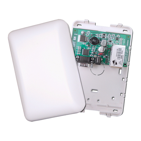
Elk M1 ELK-M1XZW User manual

ELK-M1XZW
Z-WaveTM Lighting Interface
INSTALLATION
MANUAL
Z-Wave is a trademark of Zensys, Inc.
L525 7/09/07 Printed in USA
IMPORTANT INFORMATION
The ELK-M1XZW incorporates a Z-Wave factory produced transceiver module and currently supports
lighting and thermostat device categories ONLY. The current generation of Z-Wave devices do not broad-
cast or update state changes back to any controller device other than the one that commanded the change.
The results are that the M1 may not always accurately display the true state of the Z-Wave lighting devices.
In addition, a M1 rule 'event' cannot be activated by the state change of a Z-Wave light other than lights
changed by a command from the M1 itself. In other words; The ELK-M1XZW and the M1 Control do not
know if the state of a device has been changed by another controller such as a handheld remote. Likewise,
another controller or a handheld remote will not know if the device state has been changed by the M1 and
M1XZW. This is a Z-Wave issue and it is hoped that Z-Wave will remedy this in the future.

ELK-M1XZW Installation Manual
Page 2
FEATURES:
•Flash Memory for Firmware Updating
•Connects to the M1 Data Bus - RS-485
•LED Indicators for Status and Programming
•Push Button "Copy" Program Switch
•For Indoor Use Only
SPECIFICATIONS:
•Z-Wave Transceiver Frequency: 908.42 MHz
•Z-Wave Transceiver Range: Max. line of sight to nearest Z-Wave enabled
product is 50 to 100 feet, based on no obstacles or interference.
•Operating Voltage: 12 Volts D.C.
•Operating Temperature Range: 32-105 degrees F (0 - 40 degrees C)
•Current Draw: approx. 60 mA
•Housing Dimensions: 4.25" x 6.375" x 2.125"
•Circuit Board Dimensions: 2.25" x 3.95"
FCCNOTICE
Note: This equipment has been tested and found to comply with the limits for a Class B digital device,
pursuant to part 15 of the FCC Rules. These limits are designed to provide reasonable protection
against harmful interference in a residential installation. This equipment generates, uses, and can
radiate radio frequency energy and, if not installed and used in accordance with the instructions
may cause harmful interference to radio communications. However, there is no guarantee that
interference will not occur in a particular installation. If this equipment does cause harmful
interference to radio or television reception, which can be determined by turning the equipment off
and on, the user is encouraged to try to correct the interference by one or more of the following measures:
- Reorient or relocate the receiving antenna.
- Increase the separation between the equipment and receiver.
- Connect the equipment into an outlet on a circuit different from that to which the receiver is connected.
- Consult the dealer or an experienced radio/TV technician for help.
Table of Contents
Installation and Hookup of M1XZW .............................................................................................. 3
Overview - Important Things to Know ......................................................................................... 4
Programming and Operation ........................................................................................................ 5
General ...................................................................................................................................... 5
Setup and Configuration .........................................................................................................5
Programming the Lighting Device Attributes in the M1 ........................................................ 5
Replicating 'Copying' Data from a Primary Controller into the M1XZW ............................... 5
Testing the Operation .............................................................................................................. 6
Using an ElkRP Rule to Control Z-Wave Device(s)................................................................ 6
Z-Wave Network Basics ................................................................................................................ 7
System Description ................................................................................................................. 7
Repeaters ................................................................................................................................. 7
Groups - Adding (Inclusion) of Z-Wave Nodes into a Group ................................................. 7
Scenes - Adding (Inclusion) of Z-Wave Nodes into a Scene ................................................. 7
Removing (Exclusion) of Nodes from a Group or Scene ..................................................... 8
Resetting nodes ....................................................................................................................... 8
Resetting Wireless Controller ................................................................................................. 8
M1 to Z-Wave Cross Reference Table .......................................................................................... 9
Glossary of Terms ....................................................................................................................... 10
APPLICATION:
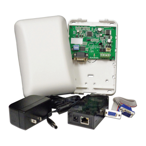
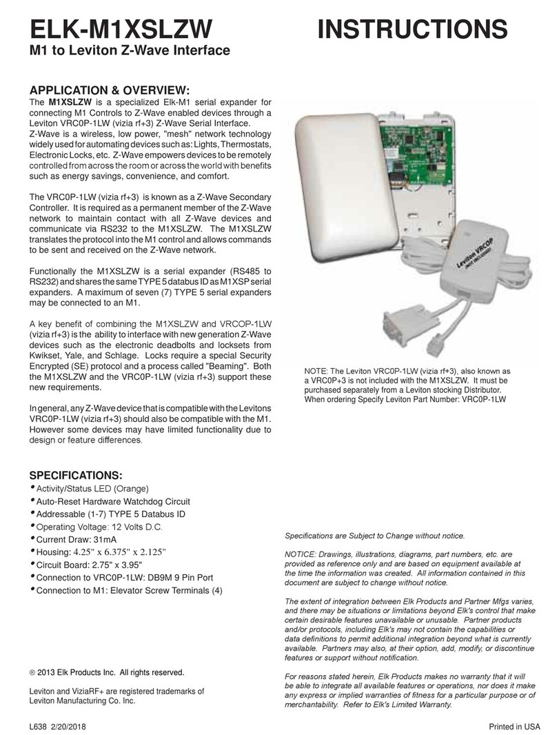
The ELK-M1XZW is a Z-Wave manufactured radio transceiver attached to an Elk Data Bus Interface. It is designed to allow an
M1 Controller to interface with Z-Wave enabled devices. Z-Wave technology is a wireless bi-directional communications
network consisting of devices such as: Plug-in Dimmer Modules, Wall Mount Switches and Dimmers, Plug-in Appliance
Modules, etc. The M1XZW interface functions as a Z-Wave Secondary Controller OR as a Z-Wave Static Update Controller
(SUC) for holding the Z-Wave system setup programming. The interface connects to the M1 RS-485 data bus and is enrolled
and identified as a Type 5 Expander. As such, it may be remotely located anywhere along the RS-485 data bus within the
maximum stated distance limits. The housing is designed for wall mounting and includes mounting screws and anchors. Z-
Wave is a trademark of Zensys, Inc.

ELK-M1XZW Installation Manual Page 3
Switch Settings
S1 S2 S3 S4
On Off Off Off
Off On Off Off
On On Off Off
Off Off On Off
On Off On Off
Off On On Off
On On On Off
Data Bus
Address
1
2
3
4
5
6
7
Table 1: Data Bus Address Switches
Other Jumper Settings
JP1 Used to engage a 120 Ohm resistor
for terminating the M1 RS-485 Data BuS.
See Data bus wiring instructions before use.
STATUS LED
Blinking = Data Bus Communications OK
Off = No Communications on Data Bus
Program "Copy" Switch
Press & Hold until Set-Up LED comes on
SET-UP (PROGRAM) LED
ON = Z-Wave Ready to copy "receive" data
from a Primary Controller
OFF = Normal Operation
XMIT (Transmit) LED
Blinks = W hen a Z-Wave Signal being
transmitted
This LED not on older boards
JP1 RS-485 Data Bus
Terminating Resistor Jumper
RS-485 Data Bus Connections
Address Switches
DO NOT PRESS
this button. For
factory use only.
Installation and Hookup of M1XZW
INSTALL UNIT * SET ADDRESS AND OPTION JUMPERS * ACTIVATE BUS ENROLLMENT PROCESS
The M1XZW is a Type 5 Expander device which may be remotely located anywhere along the RS-485 data bus within the
maximum stated distance limits. The housing is designed for wall mounting and includes mounting screws and anchors.
1. Turn Off the Control Panel power before making any connections.
2. Wiring: Make all wiring connections as follows:
“+12V” connects to the "+VKP" 12 Volt data bus terminal on the Control
“A” connects to the "Data A" data bus terminal on the Control
“B” connects to the "Data B" data bus terminal on the Control
“Neg” connects to the "NEG" negative data bus terminal on the Control
NOTE: Refer to the Control Installation Manual about proper connections of data bus devices and EOL termination. If you
are terminating the data bus at the M1XZW module, install the black jumper onto “JP1”.
3. Addressing: Address switches are binary coded and must be set for a value of from 1 to 7 as shown in Table 1. Each
switch has a position OFF or ON (binary value 0 or 1) and a decimal value of (1, 2, 4, or 8). The total decimal value for the
"ON" switches equals the data bus address. The M1XZW is a Type 5 expander like the M1XSP. Each Type 5 Expander on
the same RS-485 data bus must have a unique address. Therefore, the M1XZW must be set to an address that doesn't
conflict with any other Type 5 expander(s). Sequential addresses (1,2, 3, etc) are suggested for organization purposes.
4. Power On: Turn the Control Panel power on after all connections are complete.
5. Enrolling the M1XZW: After connecting the M1XZW to the Control, it must be enrolled as a new bus module. From the
Keypad access the Installer level programming. Select Menu 01-Bus Module Enrollment. Press the right arrow key to
start the enrollment. When the keypad indicates enrollment complete, press the right arrow key to view the results.
Among the displayed enrolled devices there should be a type 5 (T5) device at whatever address you just selected. Make
sure the number of enrolled modules displayed matches the number of modules in the system. The Status LED on the
M1XZW should start blinking about once per second.
NOTE: If it becomes necessary to replace an already installed data bus device, set the new unit to the same address as
the old unit and repeat the enrollment process. If a device is permanently removed, the enrollment process must be
performed after removal in order to un-enroll the unit and thereby prevent a "missing" trouble condition.

ELK-M1XZW Installation Manual
Page 4
Overview - Important Things to Know
There are numerous manufacturers of Z-Wave enabled devices and components such as: Handheld Primary Controllers,
Plug-in Dimmer Modules, Wall Lighting Switches, Occupancy sensors, etc. The ELK-M1XZW interface is essentially a Z-Wave
Secondary Controller or Static Update Controller (SUC), designed to allow an M1 Control to communicate with and operate
the devices on an established Z-Wave network. The M1XZW cannot be used for setup or configuration of a Z-Wave network
as this requires a Primary Controller. I.E. HomePro ZTH100 or equivalent. Using a Handheld Primary Controller, the Z-Wave
devices are programmed and linked together to form a communications network. Once the network has been installed and
configured with the Primary Controller, the configuration is then replicated or copied into the M1XZW Interface. The M1XZW
will then be able to activate or operate the networked devices. Keep in mind that any changes or modifications to a Z-Wave
network must be done using a Primary Controller and the changes then copied into the M1XZW.
!Based on the current generation Z-Wave protocol, Z-Wave Transceivers (Devices) cannot broadcast or send status
update changes back to any handheld or automation controller with the exception of a confirmation reply to a
controller that just issued a command to change. Equally important, if a device (light switch, etc.) is manually
operated it does not broadcast any status change at all. The obvious issues are that automation interfaces such as
the Elk-M1XZW, including Elk Keypads, and Elk's Virtual Keypad software cannot remain in-sync with the true state
of Z-Wave devices if their state is not broadcast or available. This is not unique to Elk. Other manufacturers of Z-
Wave controllers face the same dilemma. One might think that a periodic polling command for status would provide
a solution. However, the poll intervals and the potential detrimental loading effect on the radio network is uncertain.
Even with polling, there would still be a time lag during which displayed status would be out of sync. It is hoped that
Z-Wave will some day add Status Broadcast to their protocol.
!Since the Z-Wave protocol does NOT include Broadcasting of Status Changes, a rule in the M1 cannot use Z-Wave
Devices as activators or conditionals. In other words, the M1 Control does not know if the state of a Z-Wave device
has been manually changed or changed by another controller. Likewise, another controller such as a handheld
remote will not know if the Z-Wave device state has been changed by the M1XZW and M1. As already stated, this is
an issue with the Z-Wave protocol and it is hoped that Z-Wave will remedy this in the future.
!Be assured that the Z-Wave Protocol and devices have been designed to be very reliable, even though they do not
provide broadcast for status updates. Consequently, a possible alternative to the issue of being out-of-sync would
be to implement a "send only" policy, whereas the M1 only sends group or scene commands without regard to any
current status. To accomplish this: a) do not select the "Show" option for any lighting device in the Elk-RP Program-
ming Software. b) when writing a rule, only issue Group commands (Devices 01-64) or Scene commands (Devices
65-96). c) do not write any rule that attempts to use the lighting status of a Z-Wave device.
Groups: There are 64 Z-Wave Groups. Each Group can have up to 232 units (individual switches) assigned to it. A Group
can ONLY be turned on or off. When a Group command is issued, the controller that issued the command will
receive a status message. Provided all units in that Group respond correctly, a Group "Success" status will be
received. However, if any unit in that Group fails to respond, a Group "Fail" status will be received. It is very impor-
tant to note that a Group Status Message is a single reply that is ONLY sent to the Controller that originally sent
the Group command. The status of each Unit within a Group IS NOT TRANSMITTED.
In the M1 Control family the Z-wave Groups overlay lighting device addresses 01 to 64, or X10 address A01 to D16.
I.E., Group # 1 = Lighting Device 01 (A01), etc.
Scenes: There are 32 Z-Wave Scenes. Each Scene can have up to 58 units assigned it. A Scene can be turned On, Off, or
set to a Level (dim). When a Scene command is issued, the controller that issued the command will receive a
status message. Provided all units in that Scene respond correctly, a single Scene "Success" status will be
received. However, if any unit in that Scene fails to respond, a Scene "Fail" status will be received. It is very impor-
tant to note that a Scene Status Message is a single reply that is ONLY sent to the Controller that originally sent
the Scene command. The status of each Unit within a Scene IS NOT TRANSMITTED.
In the M1 Control family the Z-wave Scenes overlay lighting addresses 65 to 96, or X10 addresses E01 to F16.
I.E., Scene # 1 = Lighting Device 65 (E01), etc.
Unit (Nodes): There are 160 addressable Z-Wave Units. Units can be turned On, Off, or set to a Level (dim). When a Unit
command is issued, the controller that issued the command will receive a status message confirming either
"Success or Fail". It is very important to note that a Unit Status Message is ONLY sent to the Controller that
originally sent the Unit command.
In the M1 Control family the Z-Wave Units overlay lighting addresses 97 to 256, (X10 addresses G01 to P16).
I.E., Unit #1 = address 97 (G01), etc.

ELK-M1XZW Installation Manual Page 5
Programming and Operation
General
Depending on installation requirements, Z-Wave nodes can be configured and controlled in groups, scenes, or individual
nodes (units). The maximum capacity of an M1 Controller is 256 Lighting devices and the capacity for Z-Wave operation is
allocated within these 256 devices. Each lighting device number in the M1 has been assigned a corresponding Z-Wave Group,
Scene, or Node number. For example, to turn ON all light(s) assigned to Z-Wave group 1 you would execute an M1 command to
turn on Lighting Device 1 (Lighting Device 1 corresponds to Z-Wave group 1). A typical M1 rule command would be "THEN
TURN Z-Wave Group 1 [1 (A1)] ON". Below is a brief description of Groups, Scenes, and Nodes. Refer to Table 2 for a complete
reference of the Lighting Device to Z-Wave allocations. NOTE: The M1 Lighting Device TYPE must be programmed as "Serial
Expander" for every Lighting Device to be used with Z-Wave. In the above example, program the NAME for Lighting Device 1
as "Z-Wave Group 1". This can easily be done through the ElkRP software.
Setup and Configuration
The M1XZW Z-Wave Interface can be used to operate and control an established Z-Wave network but it cannot be used to
configure or setup a network. Only a Z-Wave Primary Controller such as the HomePro ZTH100 or equivalent can be used to
setup a network. Please refer to the instructions that accompany the Primary Controller for detailed setup instructions. This
manual details the procedures for replicating or 'Copying" the data from a Z-Wave Primary Controller into the M1XZW so that it
may then be used to operate lighting and other networked devices.
For additional information on the capabilities and operation of a Z-Wave network, please refer to the individual manufacturer
instructions that accompany your Z-Wave Modules and Z-Wave Primary Controller.
Programming the Lighting Device Attributes in the M1
Using the ElkRP software, program the Lighting Device Attributes for every light that will be controlled via Z-Wave. At a minimum,
you must "Format=Serial Expander", "Type=On/Off Switch or Dimmer" (depending on the device capability), and the
Name=description of the device (group,scene,etc.).
Replicating 'Copying' Data from a Primary Controller into the M1XZW
Once the Z-Wave network has been configured using the Z-Wave Primary "Handheld" Controller, the data must be copied into
the M1XZW Interface (Secondary Controller). Note: These instructions reference the use of a HomePro ZTH100 Primary
Controller. If using another brand of Primary Controller it may be necessary to cross reference these instructions to
whatever brand you happen to be using.
1. Remove the cover on the M1XZW Interface.
2. Locate the small push button along the edge of the larger circuit board. next to the blinking Status LED. This button is
used in step 8 below. DO NOT press the button on top of the smaller board.
3. Hold the ZTH100 Primary Controller within 2 feet of the M1XZW Interface. (The transfer range is intentionally limited)
4. Press the MENU button on the ZTH100.
5. Press the Left Arrow on the ZTH100 until “SETUP” is displayed, then press OK.
6. Press the Left Arrow on the ZTH100 until “COPY REMOTE CTRL.” is displayed. Then press OK several times until the
display shows “SENDING…” .
7. Press and hold the PROGRAM switch on the M1XZW until the PROGRAM LED turns on with a solid glow.
8. Within 5 or 10 seconds the display should change from "Sending" to "Wait" then "Send Complete" when the download or
copy has been successfully completed.
9. If the "Send Complete" message is not shown then it may be necessary to repeat the steps again.

ELK-M1XZW Installation Manual
Page 6
Testing the Operation
Once the M1XZW has been successfully replicated from the ZTH100 it is time to do some testing. For the purpose of testing
we will assume that Group 1 has been configured in the Primary Controller and this data has been replicated into the M1XZW.
Referring to Table 2 we find that Z-Wave Group 1 corresponds to M1 Lighting Device 1.
1. On the M1 Keypad press the ELK key once.
2. Press the Right arrow key to select Menu 1-"View/Control Automation Fncts".
3. Press the Right arrow key. The top line should display "1-Tasks".
4. Press 2 or the Up arrow one time to display "2-Lighting".
5. Press the Right arrow key to select this option.
6. Depending on the M1's programming the top line may display one of two things:
"[Light Name]" OR "Enter Light"
"001:=OFF,#toChg" "Light Number=000"
7. If the bottom line displays "001:=OFF,#toChg" it is indicating the current state of Light 001.
If the bottom line displays "Enter Light" then it will be necessary to type in 001 to access Light 001.
8. Press the # key once to toggle the state from Off to On while observing any of the Z-Wave Group 1 lights to verify that they
change from Off to On. Note: If the light was already On then no change will occur. Either way, press the # key again to
toggle the state from On to Off.
9. You may continue to test other Groups, Scenes, or Nodes depending on the Z-Wave network setup. Simply cross
reference the Z-Wave numbering scheme to the M1 Lighting numbers utilizing the information found on Table 2.
Using an ElkRP Rule to Control Z-Wave Device(s)
Using ELK RP Remote Programming Software, Automation Rules can be written to control Z-Wave network devices. These
include but are not limited to Lights, Dimmers, Appliances, Thermostats, and more. The following are some typical rules
utlizing Groups, Scenes, and Nodes.
WHENEVER [Area Name] ARMED STATE BECOMES DISARMED
THEN TURN Living Rm Lights [1 (A1)] ON NOTE: Light Device 1=Group 1 which can be turned On or Off.
WHENEVER SUNSET
THEN TURN Mood Lighting [65 (E1)] ON NOTE: Lighting Device 65=Scene 1 which can turn On,Off,Brighten, or dim one
or more lights.
WHENEVER TIME IS 6:00am
THEN TURN Bathroom Light [G1 (97)] ON NOTE: Lighting Device 097=Node 1 which is a single Light unit.

ELK-M1XZW Installation Manual Page 7
A group is an association of one or more nodes so that they operate together just like one device. All
nodes in a group turn on and off as that group is turned on and off. Dimmers in a group return to their
last dim level which can differ from node to node.
Follow each of these steps for every Node. When finished with a group press OK a second time. To exit
or quit press C.
Add Unit to
Group
Groups Select
Group #
Press Button
on Unit
Unit
Included
Press
MENU OK OK
A scene is an association of one or more nodes, including the desired dim level based on the dim level at
the time of inclusion. When a scene is activated, each associated dimmer node goes to its previously
defined dim level, regardless of its recent dim level. Some nodes may get brighter, some dimmer, and
some may turn off altogether. Appliance or switch nodes have a state of off or on within a scene.
Follow each of these steps for every Node. When finished with a scene press OK a second time. To exit
or quit press the C key.
Add Unit to
Scene
Groups Select
Scene #
Press Button
on Unit
Unit
Included
Press
MENU OK OKScenes
OK
Choose Scene using:
OR
Z-Wave Network Basics
System Description
In a Z-Wave radio network, all nodes (devices) are wirelessly linked together through the state of the art communications
network featuring the patented Z-Wave technology. The Z-Wave protocol defines various device classes (types) such as
Lighting, Thermostat, Remote Controller, Static Controller, Repeater Slave, Binary Sensor, Multilevel Sensor, Pulse Meter, Entry
Control, and more to be announced or developed.
Repeaters
In the case of a controller, a Z-Wave Centralized controller such as the M1XZW, or a portable handheld controller such as the
HomePro ZTH-100 (or equivalent), only needs to be in-range of a single device (max. range approximately 100 feet). The
patented Z-Wave technology then automatically routes commands (signals) from one device to the next, effectively going around
obstacles and radio dead spots in a building. This is possible because each device can act as a repeater, re-transmitting the
commands that are sent through them to adjacent devices that might otherwise be out of range. Regardless of the Manufac-
turer (Vendor) or the device class, all devices can act as repeaters. For this reason, the more devices you have installed, the
better the reliability and coverage becomes. The Z-Wave protocol provides for a command to be routed if necessary through as
many as four different device in route to the intended device.
Important Note
While it is not within the scope of this document to fully explain the detailed operation of a Z-Wave handheld primary controller, it
is possible to explain the general steps involved in the setup of a Z-Wave network. Of primary importance is how to setup a
group, a scene, and to include or exclude devices within a group or scene. The following illustrations are based on the use of a
HomePro ZTH-100 Handheld Controller. If another brand of controller is utilized, it may be necessary to modify the steps
accordingly.
Groups - Adding (Inclusion) of Z-Wave Nodes into a Group
Scenes - Adding (Inclusion) of Z-Wave Nodes into a Scene

ELK-M1XZW Installation Manual
Page 8
Add Unit to
Group
Groups
Press Button
on Unit
Removed
From Group
Press
MENU OK
Remove Unit
from Group
OK
Choose
Groups
or
Scenes
Using: Scenes OK Add Unit to
Scene
Remove Unit
from Scene
Are You
Sure?
Are You
Sure?
Select
Group
or
Scene
Using:
OK
OK Press Button
on Unit
Removed
From Group
Removing (Exclusion) of Nodes from a Group or Scene
Resetting nodes
Resetting Wireless Controller
If a Node is to be moved to a new position or added to a new network it has to be reset before doing so.
Setup Reset
Unit
Set Time
Press Button
on Unit
Are You
Sure?
Press
MENU OK
OK
OK Set Time
Press Button
on Unit
If a wireless controller has been used for demonstrations or bench testing it may be desirable to reset it
prior to actual use on a 'real' installation. There are two ways to reset, "user data only" or "factory
default". User data will only reset groups, scenes, and names. The controller will still retain information
about the modules that have been added to the network. A factory default reset should be used with
extreme care. It will clear groups, scenes, names, and will delete all modules from the network.
NOTE: The ELK-M1XZW does not need to be manually reset as it will automatically erase each time the
data from a handheld controller is "replicated" or copied down to it.
Setup Reset
Remote Ctrl.
Set Time
Press
MENU OK
OK
Wait . . . . . Reset
Completed
Are You
Sure?
Are You
Sure?
Select
User Data
or
Factory Default
Using:
OK
OK Wait . . . . . Reset
Completed

ELK-M1XZW Installation Manual Page 9
Z-Wave
Group #
Equiv.
1
2
3
4
5
6
7
8
9
10
11
12
13
14
15
16
17
18
19
20
21
22
23
24
25
26
27
28
29
30
31
32
33
34
35
36
37
38
39
40
41
42
43
44
45
46
47
48
49
50
51
52
53
54
55
56
57
58
59
60
61
62
63
64
ELK
Lighting
Device #
1
2
3
4
5
6
7
8
9
10
11
12
13
14
15
16
17
18
19
20
21
22
23
24
25
26
27
28
29
30
31
32
33
34
35
36
37
38
39
40
41
42
43
44
45
46
47
48
49
50
51
52
53
54
55
56
57
58
59
60
61
62
63
64
PLC
(X-10)
Equiv.
A01
A02
A03
A04
A05
A06
A07
A08
A09
A10
A11
A12
A13
A14
A15
A16
B01
B02
B03
B04
B05
B06
B07
B08
B09
B10
B11
B12
B13
B14
B15
B16
C01
C02
C03
C04
C05
C06
C07
C08
C09
C10
C11
C12
C13
C14
C15
C16
D01
D02
D03
D04
D05
D06
D07
D08
D09
D10
D11
D12
D13
D14
D15
D16
Z-Wave
Scene #
Equiv.
1
2
3
4
5
6
7
8
9
10
11
12
13
14
15
16
17
18
19
20
21
22
23
24
25
26
27
28
29
30
31
32
ELK
Lighting
Device #
65
66
67
68
69
70
71
72
73
74
75
76
77
78
79
80
81
82
83
84
85
86
87
88
89
90
91
92
93
94
95
96
PLC
(X-10)
Equiv.
E01
E02
E03
E04
E05
E06
E07
E08
E09
E10
E11
E12
E13
E14
E15
E16
F01
F02
F03
F04
F05
F06
F07
F08
F09
F10
F11
F12
F13
F14
F15
F16
Z-Wave
Node #
Equiv.
1
2
3
4
5
6
7
8
9
10
11
12
13
14
15
16
17
18
19
20
21
22
23
24
25
26
27
28
29
30
31
32
33
34
35
36
37
38
39
40
41
42
43
44
45
46
47
48
49
50
51
52
53
54
55
56
57
58
59
60
61
62
63
64
65
66
67
68
69
70
71
72
73
74
75
76
77
78
79
80
ELK
Lighting
Device #
97
98
99
100
101
102
103
104
105
106
107
108
109
110
111
112
113
114
115
116
117
118
119
120
121
122
123
124
125
126
127
128
129
130
131
132
133
134
135
136
137
138
139
140
141
142
143
144
145
146
147
148
149
150
151
152
153
154
155
156
157
158
159
160
161
162
163
164
165
166
167
168
169
170
171
172
173
174
175
176
PLC
(X-10)
Equiv.
G01
G02
G03
G04
G05
G06
G07
G08
G09
G10
G11
G12
G13
G14
G15
G16
H01
H02
H03
H04
H05
H06
H07
H08
H09
H10
H11
H12
H13
H14
H15
H16
I01
I02
I03
I04
I05
I06
I07
I08
I09
I10
I11
I12
I13
I14
I15
I16
J01
J02
J03
J04
J05
J06
J07
J08
J09
J10
J11
J12
J13
J14
J15
J16
K01
K02
K03
K04
K05
K06
K07
K08
K09
K10
K11
K12
K13
K14
K15
K16
Z-Wave
Node #
Equiv.
81
82
83
84
85
86
87
88
89
90
91
92
93
94
95
96
97
98
99
100
101
102
103
104
105
106
107
108
109
110
111
112
113
114
115
116
117
118
119
120
121
122
123
124
125
126
127
128
129
130
131
132
133
134
135
136
137
138
139
140
141
142
143
144
145
146
147
148
149
150
151
152
153
154
155
156
157
158
159
160
ELK
Lighting
Device #
177
178
179
180
181
182
183
184
185
186
187
188
189
190
191
192
193
194
195
196
197
198
199
200
201
202
203
204
205
206
207
208
209
210
211
212
213
214
215
216
217
218
219
220
221
222
223
224
225
226
227
228
229
230
231
232
233
234
235
236
237
238
239
240
241
242
243
244
245
246
247
248
249
250
251
252
253
254
255
256
PLC
(X-10)
Equiv.
L01
L02
L03
L04
L05
L06
L07
L08
L09
L10
L11
L12
L13
L14
L15
L16
M01
M02
M03
M04
M05
M06
M07
M08
M09
M10
M11
M12
M13
M14
M15
N16
N01
N02
N03
N04
N05
N06
N07
N08
N09
N10
N11
N12
N13
N14
N15
N16
O01
O02
O03
O04
O05
O06
O07
O08
O09
O10
O11
O12
O13
O14
O15
O16
P01
P02
P03
P04
P05
P06
P07
P08
P09
P10
P11
P12
P13
P14
P15
P16
NOTES:
1. Refer to page 4 "Overview - Important Things to Know".
2. This chart identifies the M1 Lighting Device numbers as they
relate to Z-Wave Group, Scene, or Node commands.
2. The PLC (X10) column is for reference only.
M1 to Z-Wave Cross Reference Table

ELK-M1XZW Installation Manual
Page 10
Glossary of Terms
Association - The linking together of two nodes (units) so that one node will send information to the other node. The node
doing the sending is the source and the node receiving the information is the destination.
Group - A set of one or more modules that are to be operated together as if they were one device. More specifically, every
module that is included in a group will switch on or off together as that group is turned on and off. When a group is activated,
each Light or Lamp module in that group turns on, returning to its last dim level - a level that in general, will differ from module
to module. Appliance Modules may also be included in groups. There are 64 Z-Wave lighting Groups in the Z-Wave protocol.
Node (Unit) - A single Module entity within the Z-Wave network. It could be a Plug-in Dimmer Module, Appliance Module, Wall
Switch, Wall Dimmer, etc. There are 160 addressable Z-Wave unit nodes as described in the Z-Wave protocol.
Scene - To link or 'associate' one or more modules, except that the controller stores not only the association, but also the dim
level for each Module. The dim level is stored at the time that a Module is added to a scene. Consequently, when a scene is
activated, the Modules will all go to their previously defined dim levels regardless of what their most recent dim level may have
been. Some Modules may get brighter while others may be pre-programmed by the user to become dimmer. Because
Appliance and Wall Switch Modules are switching devices without dimming capability, they will either be defined as on or off
when added to a scene. There are 32 Z-Wave lighting Scenes in the Z-Wave protocol. Each Scene can have a maximum of
58 Nodes or individual devices assigned it.
Replicate - To transfer or copy the setup and configuration information between a handheld Primary Controller and a Second-
ary Controller.
Route - If an obstacle or radio dead spot exists between two Z-Wave modules, Z-Wave automatically repeats or passes the
signal from one device to the next, effectively going around obstacles and radio dead spots in a building. Like wise, if two
devices are not within range of one another, a route can be manually assigned to the source module (the module sending the
information). This essentially enables devices to communicate at long ranges since the signal is repeated or "bounced" until
it reaches the receiving module.
Status Reply - The process of a device transmitting its current state (on, off, dim, etc.) in response to an individual node or unit
change command from a controller. At the present time, Z-Wave devices ONLY respond with their status to the specific
controller that commanded their change. Secondly, Z-Wave devices DO NOT respond with their status when a Group or
Scene command is issued. Z-WAVE DOES NOT BROADCAST STATUS CHANGES TO OTHER CONTROLLERS WITHIN THE
NETWORK.

PO Box 100
3266 US Hwy 70 West
Hildebran, NC 28637
828-397-4200 828-397-4415 Fax
http://www.elkproducts.com
Table of contents
Other Elk Recording Equipment manuals
