Metasys NIB-96 User manual

Fire Management Accessories Manual 445
Network Interface Board Section
Technical Bulletin
Issue Date 0392
© 1992 Johnson Controls, Inc. 1
Order No. 445-101
lntroduction 3
•
Description 3
Network Design Guidelines 5
•
Design Considerations 5
•
Network Requirements for UL Listed Panels 8
•
Network Requirements for ULC Listed Panels 8
•
NFPA Standards 9
•
Installation Precautions 9
Installation Procedures 11
•
Circuit Ratings 11
•
Installing the Central FACP 12
•
Installing the Network Interface Board 15
•
Installing the Remote FC-2000 16
•
Installing the Remote IFC-2020/IFC-1010 20
NIB-96 Network Interface Board

2 Network Interface Board—NIB-96 Network Interface Board

Network Interface Board—NIB-96 Network Interface Board 3
lntroduction
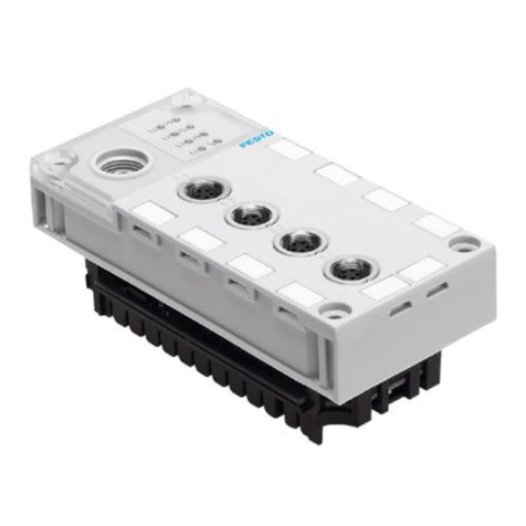
The Network Interface Board (NIB-96) is a microprocessor controlled
module that allows points on remote fire alarm panels to be displayed and
controlled from a central fire alarm panel. This manual describes how to
network remote fire panels to a central IFC-2020 Intelligent Fire
Controller or IFC-1010 Intelligent Fire Controller. The remote control
panels could be any mix of IFC-2020, IFC-1010, or FC-2000 systems.
Central FACP
IFC-2020
Remote Fire Alarm Control Panel
NIB-96
NIB-96
Remote Fire Alarm Control Panel
To Next Remote Fire
Alarm Control Panel
Figure 1: Networking Remote Fire Alarm Panels to a Central FACP
Description

4 Network Interface Board—NIB-96 Network Interface Board
The NIB-96 provides the following capabilities:
•Up to 10 LIB-200s can be installed in the central IFC-2020.
•Up to 2 LIB-200s can be installed in a central IFC-1010.
•Each LIB-200 can support a maximum of 12 NIB-96 boards (at 8
points each) or a maximum of 96 NIB points.
•Each remote fire control panel can report as many as 96 inputs/outputs
or as few as 8 inputs/outputs.
•Multiple remote fire control panels can be monitored and controlled by
a single central control panel.
•The central fire control panel can monitor and control up to 960 remote
alarm inputs/output points. Each remote input/output point consumes
one of the possible module addresses in the central control panel.
•The alarm/trouble/normal status, of each remote device or zone that is
mapped to the central control panel, is reported to the central panel for
action.
•A few points in each NIB-96 are reserved for system functions such as
system reset of remote fire control panels from the central control
panel. Remote panel troubles, not individually reported to the central
control panel by the NIB-96, are grouped together and reported at one
of these reserved points.

Network Interface Board—NIB-96 Network Interface Board 5
Network Design Guidelines
It is important that you plan out the requirements of your fire alarm system
well in advance of installation. You must consider questions such as:
•Which controller will I designate as my “central” fire alarm control
panel?
•How many remote points will this system provide?
•What types of input and output points will be installed?
•Which controller(s) will control remote outputs: the central FACP or
the “remote” FACPs?
•How many NIB-96 boards will be supported?
•What are the agency requirements for this networked system?
The following paragraphs provide guidelines for these types of questions.
The heart of the fire alarm system network is the Network Interface Board
(NIB). The NIB is a microprocessor controlled module that connects
remote Fire Alarm Control Panels (FACP) to a central FACP. The
“central” FACP is an IFC-2020 or IFC-1010. The “remote” FACPs could
be a mix of IFC-2020, IFC-1010, or FC-2000 controllers. One to four
NIB-96 modules may be physically located in each remote FACP. Each
NIB-96 can report as few as 8, or as many as 96 points, to the central
FACP. Multiple remote FACPs can be monitored and controlled by a
single central FACP.
Note: Each fire alarm network can contain only one central FACP.
Design
Considerations

6 Network Interface Board—NIB-96 Network Interface Board
Figure 2: Network Configuration with Central IFC-2020 or IFC-1010
Notes:
1. Each LIB-200 can support a maximum of 12 NIB-96 boards, but no
more than 96 total points can be reported and/or controlled by the LIB-
200.
2. Each NIB may be set to report as few as 8 points or as many as 96
points.
3. See Installing the IFC-2020 document for configuring the fire system
for transmission to the central station.
4. Each remote FACP uses four points for CPU functions.
Central FACP
IFC-2020 or IFC-1010
Remote FACP
IFC-2020. IFC-1010, FC-2000
NIB-96
SLC Loop
M500MJ
and/or
M500CJ
Modules
To Remote Station,
Municipal Box or Central
Station Receiving System, if required by
specification of local building codes to comply
with a system standard such as NFPA.
See Agency Requirements in
the Engineering an IFC-2020 document
for more information on engineering and installing
NFPA 71 and NFPA 72 systems.
NIB-96
NIB-96
AIM:2:00
SLC
Loop Remote FACP

Network Interface Board—NIB-96 Network Interface Board 7
The NIB has two serial interfaces:
•To the central FACP, it communicates using one of the central FACP’s
signaling line circuits. The NIB-96 emulates a group of M500MJ
monitor modules and M500CJ control modules (up to 96), using the
monitor module series (LxMyy) addresses on the SLC.
•To the remote FACP, the NIB communicates using the RS-485
annunciator interface, and emulates one or two ACS annunciators (up
to 128 annunciator points, of which only 96 may be used).
With the NIB at the maximum (96 point) configuration, each central
FACP SLC loop may only support one remote FACP. With the NIBs
configured for minimum size (8 points), 12 remote FACPs can be
supported by one SLC loop. Note that the central FACP can control
additional remote FACPs by installing more SLC loops (more LIB-200s).
The capacity of a 10 loop central station FACP is 960 total remote FACP
points, less four remote FACP CPU points for each NIB connected to the
central FACP.
Monitor module type ID addresses, not used by the NIB-96, can be used
for other purposes, such as M500MJs, M500CJs, etc. Analog detectors
can also be connected to the SLC serving NIB-96 boards.
Networked systems can concentrate large systems by grouping many
remote FACP points together in a software zone and only reporting alarms
and troubles for the software zone as a single NIB point. This technique
allows a very large system point capacity. However, if this zone grouping
of remote FACP addressable device points is employed, the user at the
central FACP does not have the exact location of the event from the
remote FACP. If the remote FACP is connected to a MetasysNetwork,
Metasys can provide the exact location as a secondary alarm reporting
device.
Since the NIB reports remote status as module points, not detectors,
analog information is not available at the central FACP. Analog
information is available only at the remote FACPs or through a Metasys
Network. Sensor Watch and Auto Test errors still reports to the central
FACP as a trouble. If the point is mapped to an annunciator on the remote
panel, then the point shows the trouble. If the point is not mapped to an
annunciator, then a general trouble is produced at the central panel.
The IFC-2020 network has full control-by-event capability. An alarm at
any point on any remote FACP may activate any point(s) on any other
remote FACP(s). The central FACP can be programmed with all
instructions to accomplish this. The central FACP keypad also provides
System Reset to all remote FACPs under its control. Alarm and trouble
acknowledgement is performed at the central FACP. The central FACP
has full Signal Silence capability over any remote FACP output points it
controls.

8 Network Interface Board—NIB-96 Network Interface Board
NIB-96 network installations requiring Underwriter’s Laboratories in the
United States must follow these guidelines.
You cannot program control-by-event (C-B-E) statements for control of
indicating devices in both the central and remote FACPs. For control-by-
event programming of indicating appliance circuits and relays as a
function of addressable initiating devices or initiating device circuits in the
remote IFC-2020 or IFC-1010, follow these guidelines:
•If you intend to control the network with the central FACP, and have
alarms from one remote FACP activate output circuits in a different
remote FACP, do not program any control-by-event equations for the
indicating appliances (control modules) in the remote FACP. Perform
all control-by-event programming in the central FACP. This also
requires all remote FACP control modules to be mapped to the central
FACP.
•If the system does not require the central FACP to activate output
circuits in the remote FACPs, then program all control-by-event
programming into the remote FACP. Do not program any C-B-Es into
the central FACP for remote FACPs. None of the remote FACP
control modules can be mapped to the central FACP in this case.
For I/O mapping of Indicating Appliance Circuits (IACs) and relays as a
function of initiating circuits, you must program the FC-2000 as follows:
•If the central FACP controls the network system, and all alarms
generated in a remote FACP(s) activates output circuits in a different
remote FACP(s), do not program any mapping to controlled circuits in
the remote FC-2000. Perform all control-by-event (C-B-E)
programming in the central FACP for the FC-2000 outputs.
•If the system does not require that the central FACP activate output
circuits in the remote FACPs, then program all I/O mapping to
controlled circuits into the remote FC-2000s, and do not program any
into the central FACP for controlling remote output points.
NIB-96 network installations requiring Underwriter's Laboratories of
Canada listing must follow these guidelines.
In Canada, remote FACPs must be able to function as standalone units
during loss of communications with the central FACP. Therefore, each
remote FACP must be programmed for complete local signaling operation.
If the central FACP is to also control output circuits in the remote FACPs,
take care in ensuring that programming in both the central and the remote
FACPs function identically. (Both must place the same outputs into alarm
under any activation condition.)
Network
Requirements for
UL Listed FACPs
UL Requirements for
Networking the IFC-
1010/IFC-2020
UL Requirements for
Networking the FC-
2000
Network
Requirements for
ULC Listed FACPs

Network Interface Board—NIB-96 Network Interface Board 9
Note: In this case, if a remote output is Signal Silenced by the central
FACP, it silences as commanded. However, it also goes into
trouble at the central FACP because the remote commanded state
disagrees with the central commanded state.
When installed in accordance with this document, the central FACP can
meet the requirements for the following NFPA standards:
NFPA 72 Local Protective Signaling Systems
NFPA 72 Auxiliary Protective Signaling System
NFPA 72 Remote Station Protective Signaling System
NFPA 72 Proprietary Signaling System Receiving Unit
NFPA 72 Proprietary Signaling System Protected Premises Unit
NFPA 71 Central Station Service—Protected Premises Unit
NFPA 71 Central Station Receiving Unit
Note: The NIB-96 is not listed under NFPA 71 for sprinkler supervisory
service.
Select software and minimum system configuration requirements
according to this document. The remote FACPs act as multiplexing panels
for the central FACP. In addition, the remote FACPs may have indicating
appliance circuits and control relays that are commanded on or off by the
central FACP. The remote FACPs must be located within the protected
premises. The central FACP may be located remotely.
Adhere to the following guidelines to aid in problem-free installation and
long term reliability:
•Locate the system and all the system components and peripheral
equipment in the following nominal environment:
Temperature: 32° to 90° F (0° to 32° C)
Humidity: 20 to 90% R.H. (non-condensing)
•Verify that wire sizes are adequate for all initiating device and
indicating appliance circuits. Most devices cannot tolerate more than a
10% voltage drop from the specified device. Do not exceed maximum
wire lengths.
•Lightning induced transients can damage this system. Although no
system is completely immune from lightning transients and
interference, proper grounding reduces susceptibility.
•Make sure the cabinet is electrically connected to a good earth
ground.
NFPA Standards
Installation
Precautions

10 Network Interface Board—NIB-96 Network Interface Board
•This system contains static-sensitive components. Always ground
yourself before handling any circuits so that static charges are
removed from the body. Use static suppressive packaging to protect
electronic assemblies removed from the unit.
•Remove all electronic assemblies prior to any drilling, filing,
reaming, or punching of the enclosure. When possible, make all cable
entries from the sides or rear. Before making modifications, verify
that they will not interfere with battery, power supply, and printed
circuit board location.
•Do not tighten screw terminals more than 9 in-lbs. Over tightening
may damage threads, resulting in reduced terminal contact pressure
and difficulty with screw terminal removal.
•Disconnect AC power and batteries from the power supplies prior to
removing or inserting circuit boards. Failure to do so can damage
circuits.
Follow the instructions in the installation, operating, and programming
sections of this manual. These instructions must be followed to avoid
damage to the FACP and associated equipment. Proper fire control
system operation and reliability depends upon proper installation.
!
WARNING: Several different sources of power can be
connected to this fire alarm control panel.
Disconnect all sources of power before servicing.
The control unit and associated equipment may be
damaged by removing and/or inserting cards,
modules, or interconnecting cables while the unit is
energized. Do not attempt to install, service, or
operate this unit until you have read and
understood this manual.

Network Interface Board—NIB-96 Network Interface Board 11
Installation Procedures
This section describes:
•Central FACP wiring and programming
•NIB-96 features and module wiring
•Remote FC-2000—NIB mounting, wiring, and remote programming
•Remote IFC-1010/IFC-2020—NIB mounting, wiring, and remote
programming
Unless otherwise stated in this document, the wiring requirements and
specifications contained in Table 1 apply to all references to the SLC loop
and RS-485 circuit.
Table 1: Wiring Specifications
CIRCUIT NOTES
SLC Loop from Central
FACP Supervised and power-limited
Maximum wiring distance: 10,000 feet 12 AWG
Maximum Loop current: 200 mA (short circuit) or 100 mA (normal)
Maximum Loop resistance: 40 ohms
RS-485 Annunciator Trunk
from Remote FACP Supervised and power-limited
+/- 5 volts peak-to-peak
Maximum wiring distance: 4000 feet @ 22 AWG
Characteristic impedance of wiring: 100 ohms
Transmission rate: 20.833 KBAUD
Circuit Ratings

12 Network Interface Board—NIB-96 Network Interface Board
This section describes the wiring and programming requirements when
installing an IFC-2020 or IFC-1010 as the central FACP.
Remote FACPs connect to one or more Signaling Line Circuits (SLCs) in
the central FACP. The wiring requirements to connect the LIB-200 loop
is defined in Installing the IFC-2020 (FAN 448) or Installing the
IFC-1010 (FAN 448.5) document.
!
CAUTION: For U.S. installations, do not program control-by-
event (C-B-E) statements of output modules into both
the central FACP and remote FACPs because of the
possibility of installer error and program mismatch. If
you choose to enter the programming at the central
FACP, follow the instructions below. If you choose
to enter the C-B-Es at the remote FACPs, then refer to
the C-B-E programming instructions describing
remote FACPs further in this document.
There is no change in the IFC-2020 or IFC-1010 hardware or system
software in order to work as a central FACP in the network. All points in
the remote FACPs are programmed into the central FACP as supervised
monitor or control modules. Software features are programmed in the
central FACP’s data base to recognize remote FACP points as M500MJ
and M500CJ devices connected to the central FACP’s signaling line
circuit.
Follow these programming steps at the central FACP for each NIB-96.
1. Determine the SLC loop starting address and point count for each NIB.
(Also, see the section entitled Installing the Network Interface Board.)
The first NIB point is then the starting address on the SLC loop. Each
subsequent NIB point is offset from the starting address. Use Table 8
as an aid to mapping and programming NIB points.
2. Define the first NIB point as a MON software type ID for every NIB
module. Construct a general alarm C-B-E for this point. It is the
general alarm indicator for unmapped remote system points. The first
point also reports system troubles in remote FACPs to the central
FACP.
3. Do not program points 2 and 4 in the central FACP. These are used
for NIB system functions.
4. Program point 3 as a CON software type ID in the central FACP.
When System Reset is activated in the central FACP, it is also used for
system reset of the remote FACP.
Installing the
Central FACP
Wiring
Requirements -
Central FACP
Central FACP
Programming

Network Interface Board—NIB-96 Network Interface Board 13
5. If the NIB is connected to an FC-2000, NIB points 5 through 8 must
be CON software type IDs in the central FACP. These points map to
the four CPU output relays on the remote FC-2000 (i.e., bell 1, bell 2,
municipal box, and auxiliary relay).
Once you have programmed the system points described in the steps
above, you must program each of the remaining NIB points in the central
FACP. Follow these rules for assigning software type IDs to remote
points.
•In the central FACP data base, assign a supervised monitor module
type ID (e.g., MON) to initiating devices, including groups of devices
or zones.
•In the central FACP data base, assign a supervised control module type
ID (e.g., CON) to indicating appliance circuits (e.g., M500CJ, XPC-8,
or ICM-4 module points) that originate from a remote FACP data base
and are controlled by the central FACP.
•In the central FACP data base, assign a supervised software Type ID to
relays (e.g., M500CJ, XPC-8, XPR-8, or CRM-4 relays) that originate
from a remote FACP data base and are controlled by the central FACP.
•In the central FACP data base, program all speaker circuits that
originate from a remote FACP as SPKR Type IDs and are controlled
by the central FACP.
•In the central FACP data base, program all telephone circuits that
originate from a remote FACP as TELE Type IDs and are controlled
by the central FACP.
•In the central FACP data base, select the Signal Silence option for all
mapped remote control points that are to be silenced from the central
FACP.
•In the central FACP data base, use latching (non-tracking) for
initiating devices.
•If the remote FACP is to perform control-by-events of the remote
FACP output modules, then program the central FACP as NULL (no
control-by-event) for those output modules (U.S. only).
•If multiple NIBs are installed in a single IFC-2020/IFC-1010 remote
FACP, each NIB still reserves the first four points for system
functions. For the second and following NIB-96s installed in that
single remote IFC FACP, you can program the first NIB point at the
central FACP as a NOA type ID, if multiple general alarm indication
must be avoided.
Note: You must program any NIB points not used by the remote FACP
as MON type IDs at the central FACP.

14 Network Interface Board—NIB-96 Network Interface Board
The central FACP provides error codes that can help you troubleshoot
programming errors.
•The central FACP’s LIB polls the NIB-96 as part of the regular polling
cycle. The first four programming points are reserved for system
functions. If an open circuit response is detected at the trouble
address, the central FACP enters the trouble mode and displays
TROUBLE LIB?? M/S PROGRAMMING ERROR or the equivalent.
You’ll receive this error code if one or more of the following
conditions exist:
- Communication is occurring at the two restricted NIB points 2
and/or 4 (i.e., someone has programmed points 2 and/or 4 at the
central FACP, which are reserved for internal processes).
- A NIB point is disabled (or not programmed) at the central FACP
and no communication has taken place for more than 60 seconds.
(Except for the two undefined system points (2 and 4), all other
NIB points must be defined and enabled at the central FACP.)
- SLC trunk noise is causing the master message to be corrupted.
•When any other response is received at the trouble address, the central
FACP enters the trouble mode and displays TROUBLE LIB?? NIB
COMMUNICATION ERROR or the equivalent. You’ll receive this
error code if one or more of the following conditions exist:
- SLC trunk noise is causing the master message to be corrupted.
- Two or more devices are programmed for the same address on the
central FACP’s SLC loop.
•If the first NIB point indicates an open circuit trouble at the central
FACP, the remote FACP has a trouble that is not otherwise reported
by that NIB.
Error Codes

Network Interface Board—NIB-96 Network Interface Board 15
This section describes the hardware features and terminations made at the
NIB-96. The NIB-96 is typically mounted inside the remote FACP.
Mounting instructions are described later in this document.
The figure below describes the components of the NIB-96.
Figure 3: NIB-96 Components
Installing the
Network Interface
Board
P5 P4RS485SLC
P2
LED1
SLC
ON-LINE
LED2
LED3
RS485
ON-LINE
TROUBLE
P3
SWITCH SETTING NO OF POINTS
1
2
3
4
5
6
7
8
9
0
8
16
24
32
40
48
56
64
80
85
SIZE
1
2
3
4
5
6
7
8
SIZE
TENS
ONES
SW2
SW3
SW4
AUTO ACK
TIMED ACK
EVACUATE
REC ONLY
Trouble LED (Yellow)
Lights when one or more trouble conditions are detected by the SLC.
A trouble condition can be caused by: loss of RS-485 communication,
loss of SLC communication, or invalid NIB board switch settings.
RS-485 Online LED (Green)
Blinks during communication with the remote FACP.
SLC Online LED (Green)
Blinks during communication with the central FACP.
SLC and RS-485 Connections
All connections are power-limited and supervised. See
Figure 4 for terminal assignments.
Power IN
connection to Main Power Supply
(See Figure 6 for CHS-4 mounting.)
Power OUT
connection to remote FACP control
(FC-2000 only) See Figure 6.
NIB Power Requirements
Standby: 22 mA
Alarm: 22 mA
Power Connector
Connect to remote IFC-2020 or IFC-1010 (via ICA-4
chassis).
SLC Start Address Switches
Set to 01 to 89. Note that the sum of ADDRESS +
NUMBER OF POINTS may not exceed 97.
SIZE Select Switch
Select number of points monitored on the remote and
central FACPs.
Set to 8, 16, 24, 32, 40, 48, 56, 64, 80, or 96.
See Table 3 for switch settings.
NIB-96B
SW1

16 Network Interface Board—NIB-96 Network Interface Board
See the figure below for proper terminations at the NIB-96. The RS-485
circuit requires a serial connection. Connect only one wire to each screw
terminal. Connect the enclosure to one of the earth ground terminals.
Figure 4: NIB-96 Wiring Requirements
In a remote FC-2000, the NIB mounts behind the third and fourth modules
to the right of the CPU. The NIB fastens to the base of the CHS-4 chassis
using three hex standoffs (provided), which are screwed onto three PEM
studs. Attach the NIB to the three standoffs using the mounting screws
provided. See Figure 5.
Figure 5: Mounting the NIB-96 in a Remote FC-2000
NIB-96 Wiring
Requirements
P5
P4
RS-485SLC
8 7 6 5 4 3 2 1 6 5 4 3 2 1
SLC Loop IN (+)
SLC Loop IN Shield
SLC Loop IN (-)
Earth Ground
SLC Loop OUT (+)
SLC Loop OUT Shield
SLC Loop OUT (-)
Earth Ground
RS-485 Loop IN (+)
RS-485 Loop IN (-)
No Connection
RS-485 Loop OUT
(+) (-)
NIB-96B
Installing the
Remote FC-2000
Mechanical
Installation
NB CHS-4
STEP 1
STEP 2
NIB-96C

Network Interface Board—NIB-96 Network Interface Board 17
To connect the NIB-96 to a remote FC-2000 panel, follow these
instructions:
1. Connect the main power harness from the MPS power supply to P3 the
NIB.
2. Connect the short power harness (provided) from P2 on the NIB to the
CPU-2000. See Figure 6 for wiring diagram and all terminal
assignments.
3. Connect the RS-485 annunciator signal from the two-terminal
connector on the lower CPU board (TB-2) to the NIB RS-485 IN
terminals.
4. Connect the SLC loop from a LIB-200 module in the central FACP to
the SLC input terminals.
The NIB could support a very large remote FC-2000 (88 points in addition
to the eight points on the CPU) and use almost all of the SLC module
capacity (96 out of 99 maximum). Alternately, several smaller remote FC-
2000s could be supported by a single multi-drop SLC. For example, six
FC-2000 remotes, each with eight initiating zones, can be monitored and
controlled by one SLC.
The remote FACP points are automatically assigned to the NIB-96 similar
to the assignment of annunciator points on the FC-2000. See the FC-2000
Technical Manual (FAN 406).
Since the points are automatically assigned, an ACM or LDM annunciator
can still be connected to the RS-485 trunk, if the annunciator is configured
in a “receive only” mode of operation.
Note: An annunciator in this configuration is not supervised for data on
the RS-485, nor for the power input. See the IFC-2020 Technical
Manual (FAN 448) or IFC-1010 Technical Manual (FAN 448.5)
for installation, setup, and design configurations to accommodate
the lack of supervision.
Electrical
Installation for
Remote FC-2000

18 Network Interface Board—NIB-96 Network Interface Board
Figure 6: Wiring the NIB-96 to a Remote FC-2000
Table 2: Remote FC-2000 Terminal Assignments
TERMINAL ASSIGNMENTS
SLC Loop IN From: LIB-200 SLC OUT of central FACP or previous addressable device
To: NIB-96 P5 terminals 1(+) and 3 (-)
SLC Loop OUT From NIB-96 P5 terminals 5 (+) and 7 (-)
To: Next device on SLC Loop
RS-485 Loop IN From: CPU-2000 TB2 terminals 2(+) and 1 (-)
To: NIB-96 P4 terminals 5 (+) and 3 (-)
RS-485 Loop OUT From: NIB-96 P4 terminals 6 (+) and 4 (-)
To: Next device on RS-485 Loop
The SW2 rotary “Size” switch on the NIB sets the number of remote
points the central FACP monitors as individual points. The “Size” number
set for the FC-2000 is usually eight times the number of modules installed,
including the CPU-2000.
P5 P4
RS485
SLC
P2
P3
CPU-2000
J7
TB2
P2
MPS-24,
MPS-24A, or
MPS-24B
Main Power
Harness
(#71086)
Main Power
Harness
(#75099)
NIB-96
RS-485 IN
(+)(-)
SLC Loop OUT SLC Loop IN
RS-485 Loop OUT
To Other
Annunciators
(if used)
NIB-96D
Setting NIB-96 SW2
Rotary Switch for
Remote FC-2000
SIZE SW2

Network Interface Board—NIB-96 Network Interface Board 19
Table 3: Setting the Size Switch for Number
of “Remote” Circuits
SIZE SWITCH SETTING NUMBER OF REMOTE
POINTS
18
216
324
432
540
648
756
864
980
096
SW3 and SW4 rotary switches set the “starting address” of the remote
circuits connected to the central FACP. The NIB-96 assumes all modules
address from the [START ADDRESS] to [START ADDRESS +
NUMBER OF REMOTE POINTS (MINUS 1)] on the SLC loop. The
total of START ADDRESS + NUMBER OF REMOTE POINTS must be
97 or less.
The following table describes the correct NIB-96 dip switch settings for a
remote FC-2000 configuration.
Table 4: NIB-96 Dip Switch Settings for Remote FC-2000
DIP SWITCH FC-2000
1. AUTO-ACK ON
2. TIMED ACK OFF
3. REMOTE IFC-1010/IFC-2020 FACP OFF
4. NOT USED OFF
5. CENTRAL IFC-1010/IFC-2020 FACP ON
6. RECEIVE-ONLY OFF
7. IFC-1010/IFC-2020 ADDRESS OFF
8. IFC-1010/IFC-2020 ADDRESS OFF
Setting NIB-96 SW3
and SW4 Switches
for Remote FC-2000
TENS
ONES
SW3
SW4
NIB-96 Dip Switch
SW1 Settings for
Remote FC-2000

20 Network Interface Board—NIB-96 Network Interface Board
Follow these programming rules for the FC-2000:
•SWITCH INHIBIT cannot be used.
•ANNUNCIATOR INSTALL must be set to one of two positions:
- 1-64 points if the NIB size is set for 64 or less
- 64-128 points if the NIB size is set for 80 or 96 points
•ANNUNCIATOR MODE must be set to “Output Control.”
•Remote annunciators used with the remote FC-2000 must be set to
“Receive Only.”
!
CAUTION: In the U.S., you cannot program control-by-event
mapping of output modules into both the central
FACP and remote FACPs because of the possibility
of installer error and program mismatch.
In a remote IFC-2020 or IFC-1010, the NIB-96 plugs into a slot on the
ICA-4 chassis. If the IFC-2020 or IFC-1010 is in an A-size cabinet (only
one ICA-4), the NIB-96 mounts beneath the CPU or the SIB. If a second
or third ICA-4 chassis is available, we recommend that you mount the
NIB-96 in one of the two upper slots to permit easy access to NIB wiring
and switch settings. Note that the NIB-96 mechanically eliminates one
LIB-200 position, and in some instances, you could need to install an
additional chassis. As an alternative, the remote FACP may use a CHS-4
chassis to mount the NIB-96. See Figure 5 for mounting the NIB-96 in a
CHS-4 chassis.
Remote FC-2000
Programming
Installing the
Remote IFC-2020
/IFC-1010
Mechanical
installation
Table of contents
