Elk ELK-M1XSLZW User manual

L638 2/20/2018 Printed in USA
Specications are Subject to Change without notice.
NOTICE: Drawings, illustrations, diagrams, part numbers, etc. are
provided as reference only and are based on equipment available at
the time the information was created. All information contained in this
document are subject to change without notice.
The extent of integration between Elk Products and Partner Mfgs varies,
and there may be situations or limitations beyond Elk's control that make
certain desirable features unavailable or unusable. Partner products
and/or protocols, including Elk's may not contain the capabilities or
data denitions to permit additional integration beyond what is currently
available. Partners may also, at their option, add, modify, or discontinue
features or support without notication.
For reasons stated herein, Elk Products makes no warranty that it will
be able to integrate all available features or operations, nor does it make
any express or implied warranties of tness for a particular purpose or of
merchantability. Refer to Elk's Limited Warranty.
APPLICATION & OVERVIEW:
The M1XSLZW is a specialized Elk-M1 serial expander for
connecting M1 Controls to Z-Wave enabled devices through a
Leviton VRC0P-1LW (vizia rf+3) Z-Wave Serial Interface.
Z-Wave is a wireless, low power, "mesh" network technology
widelyusedforautomatingdevicessuchas:Lights,Thermostats,
ElectronicLocks,etc. Z-Waveempowersdevicestoberemotely
controlled from across the room or across the world with benets
such as energy savings, convenience, and comfort.
The VRC0P-1LW (vizia rf+3) is known as a Z-Wave Secondary
Controller. It isrequiredas a permanentmemberofthe Z-Wave
network to maintain contact with all Z-Wave devices and
communicate via RS232 to the M1XSLZW. The M1XSLZW
translatestheprotocolintotheM1controlandallowscommands
to be sent and received on the Z-Wave network.
Functionally the M1XSLZW is a serial expander (RS485 to
RS232)andsharesthesameTYPE5databusIDasM1XSPserial
expanders. A maximum of seven (7) TYPE 5 serial expanders
may be connected to an M1.
A key benet of combining the M1XSLZW and VRCOP-1LW
(viziarf+3)isthe abilitytointerfacewithnewgenerationZ-Wave
devices such as the electronic deadbolts and locksets from
Kwikset, Yale, and Schlage. Locks require a special Security
Encrypted (SE) protocol and a process called "Beaming". Both
the M1XSLZW and the VRC0P-1LW (vizia rf+3) support these
new requirements.
Ingeneral,anyZ-WavedevicethatiscompatiblewiththeLevitons
VRC0P-1LW (vizia rf+3) shouldalsobecompatiblewith the M1.
However some devices may have limited functionality due to
design or feature dierences.
SPECIFICATIONS:
• Activity/Status LED (Orange)
•Auto-Reset Hardware Watchdog Circuit
•Addressable (1-7) TYPE 5 Databus ID
• Operating Voltage: 12 Volts D.C.
•Current Draw: 31mA
•Housing: 4.25" x 6.375" x 2.125"
•Circuit Board: 2.75" x 3.95"
•Connection to VRC0P-1LW: DB9M 9 Pin Port
•Connection to M1: Elevator Screw Terminals (4)
ELK-M1XSLZW
M1 to Leviton Z-Wave Interface INSTRUCTIONS
NOTE: The Leviton VRC0P-1LW (vizia rf+3), also known as
a VRC0P+3 is not included with the M1XSLZW. It must be
purchased separately from a Leviton stocking Distributor.
When ordering Specify Leviton Part Number: VRC0P-1LW
2013 Elk Products Inc. All rights reserved.
Leviton and ViziaRF+ are registered trademarks of
Leviton Manufacturing Co. Inc.

M1XSLZW Instruction Manual
Page 2
DO NOT attempt installation of the M1XSLZW until the entire Z-Wave network is setup wth all devices and controllers
Associated and Updated. A Leviton VRC0P-1LW (vizia rf+3) Serial Interface is required. Installers NOT experienced with
setting up a Z-Wave network are encouraged to obtain Z-Wave training before proceeding. Once the Z-Wave network
and the serial interface are setup and working the M1XSLZW is relatively easy to install. Attempting to take shortcuts
generally results in wasted time and troubleshooting.
Integrating an Elk-M1 Control to a Z-Wave network requires the following components:
QTY Part Number & Description
1 ELK-M1G or M1EZ8 Control
1 ELK-M1XSLZW M1 to Leviton Serial Interface
1 ElkRP Remote Programming Software
1 LEVITON VRC0P-1LW (vizia rf+3) Serial Interface & cable. This unit MUST have the +3 marking, i.e.
vizia rf+3. Older units are NOT COMPATIBLE and are not upgradeable! The VRC0P-1LW MUST also have
rmware version V2.33S / Z-Wave 3.11 or greater. This can be conrmed by connecting it to a PC serial port
with a serial communications program like Hyperterminal. Set it up for 9,600 Baud, 8, N, 1. On power up the
VRC0P-1LW will transmit its name and rmware ID to the Hyperterminal display screen.
1 Leviton VRUSB-1US USB Z-Wave Stick [RECOMMENDED] Primary Controller.
1 Leviton PC Installer Software [RECOMMENDED]
? Z-Wave devices (lights, thermostats, locks, etc.) Leviton vizia rf+ devices are recommended **
** Leviton viziarf+ Z-Wave devices report back their status [exception: devices DO NOT report status from Group Commands] to
all other vizia rf+ brand controllers, including the vizia rf+3 serial interface. Unfortunately, other brands/series of Z-Wave devices
(including Leviton's DZ series) may only report their status back to the single controller that commanded the change, leaving
other controllers out-of-sync and believing a device is On when it's O, or O when it's On. Although devices may be polled to
determine their status, polling is NOT practical or ecient as consumes extensive bandwidth/time and can delay or disrupt normal
communications. Polling is denitely NOT an option that should be performed on a regular basis. Leviton vizia rf+ devices do NOT
require polling!
Information in this manual about Z-Wave is NOT a substitute for actual Z-Wave training. Additional Z-Wave
information, particularly the Leviton vizia rf+ brand of Z-Wave can be found on the Leviton web site links:
http://www.leviton.com/OA_HTML/ibeCCtpSctDspRte.jsp?section=25545&minisite=10024
http://communities.leviton.com/docs/DOC-2389
http://communities.leviton.com/community/knowledgebaseforums/home_automation
Z-Wave Network: Z-Wave is a wireless (RF) 'Mesh' Network that utilizes a proprietary protocol. The network can be as simple as
two devices, or dozens of devices if the installation is large. Typical Z-Wave devices are: Controllers, Light Switches, Lamp Mod-
ules, Appliance Modules, Locks, Thermostats, etc.
Network Routing: Routing is used by a 'Mesh' network to provide primary and alternate communications paths. Z-Wave devices
have relatively short transmission range ~30 ft. or so. For extended distances messages must be routed (repeated) across the
mesh through other 'routable' devices. A message may route through a single neighbor device or multiple devices before reaching
its destination. It is very important for Z-Wave devices to be installed in their permanent location PRIOR TO INCLUSION in the
network. This way each knows what neighbors are close by. Routing is also called repeating or hopping. A Z-Wave network
allows for a maximum of 4 repeats or hops. In other words, messages can be routed through a maximum of 4 devices to reach a
destination.
Non-Routable devices - Devices that operate from Battery Only such as motion sensors, handheld remotes, and Locks do not
route or repeat Z-Wave communications. This is because they are generally in a state of sleep to preserve and extend their
battery life. They must be awakened by touch, movement, or 'beaming' before they can communicate. They are often called
'End Node Devices' since they cannot be used to route communications and are therefore at the end of the path.
Z-Wave NODE IDs: Each device in a Z-Wave Network must have a unique ID called a Node ID from a pool of 128 Nodes allowed.
Duplicate Node IDs are not permitted, and a Z-Wave device can only be a member of one network at a time. Setting up Z-Wave
devices and assigning Node IDs requires a Z-Wave Primary Controller.
Z-Wave Primary Controller: A Primary Controller is required to setup a network and assign Node IDs. The Leviton vizia rf+
VRUSB-1US USB stick Primary Controller and Installer Tool PC Software is recommend. There are other Z-Wave Primary
Controllers, but ONLY THE Leviton VRUSB-1US supports the enrollment of Locks. Other advantages of the USB Stick and PC
software is that a permanent copy of the network settings may be saved on the PC hard drive for future service.
* All setup and programming references in this manual utilized the Leviton VRUSB-1US and Installer Tool. *
STEP 1 - READ THIS FIRST!
M1XSLZW Instruction Manual Page 3
Z-Wave Secondary Controller: The VRC0P-1LW (vizia rf+3) is an example of a Secondary Controller, which can be used to
control devices but not to setup or congure them. Secondary Controllers MUST obtain a copy of the network conguration
from the Primary Controller in a step called Update Controller. In order for the VRC0P-1LW (vizia rf+3) to communicate and
control Z-Wave devices it MUST BE enrolled as a Secondary Controller and Updated from the Primary Controller.
Node Inclusion: Inclusion is the process used by a Primary Controller to add a Z-Wave device to a Network and assign it a
Node ID. Devices retain their Node ID until such time as they are Excluded (removed) from a network or factory defaulted. A
device can only belong to a single network, and must be excluded from its previous network before it may be Included with a
new network. A new Node ID will be assigned by the new network. There is no known method for moving a device to a new
network and having it retain its previous Node ID. And there is no known method for forcing a specic Node ID to a specic
device. The Primary Controller picks the next available Node ID (never used in the network) and assigns it to the device. The
Primary Controller (Leviton VRUSB-1US Stick and PC) must be held close to the Device (1-2ft) when Including.
Node Exclusion: Exclusion is the process used by a Primary Controller to remove a Z-Wave device from a network when no
longer needed. Exclusion removes the device as a member of the network and resets it to factory defaults. It DOES NOT clear
routes and associations from other network controllers or devices, and that can cause sluggish communications when devices
attempt to route through devices that are no longer present. Processes such as Network ReDiscovery and Update Controllers
should be performed after devices are Excluded or Included. This helps refresh routings and improve network performance. If
a device stops working or is removed from the premises the network can also be sluggish. Dead or removed devices MUST be
Excluded as soon as possible. The process for removing a dead or removed device may dier from regular Exclusion. For more
information see the Primary Controller Instructions or seek help from a Z-Wave device manufacturer or training event. Elk does
not produce any Z-Wave devices and cannot address Z-Wave questions. The Primary Controller (Leviton VRUSB-1US Stick
and PC) must be held close to the Device (1-2ft) when Excluding.
Association: Association is used by a Primary Controller to dene Areas and/or relationships between Z-Wave devices
(controllers, switches, dimmers, thermostats, locks, etc.) E.G. Take an area or room with a multi-button Scene/Zone Controller
Keypad and several Dimmers. The buttons MUST be associated with the Dimmers to be controlled. The Dimmers will not react
to a button press if not associated. NOTE: Not all Z-Wave devices support full association.
Update Controller: Updating transfers existing Node ID information, associations, routings, etc. from the Primary Controller to
other Secondary Controllers. This is a VERY IMPORTANT step when setting up or making changes to a Z-Wave network. The
Primary Controller (Leviton VRUSB-1US Stick and PC) must be held close to the Device (1-2ft) when Updating. Occasionally
the VRC0P+3 Secondary Controller may fail to update "Error=Could not update VRC0P". In this situation the only solution may
be to Default it and repeat the Inclusion process followed by the Update and Associate processes.
VERY IMPORTANT! Updating Controllers should be done ANY TIME changes are made to that network. This populates
information about new devices and cleans up (removes) remnants of devices that have been removed or excluded.
Summarized steps for setting up a Z-Wave Network using the Leviton VRUSB-1US and Installer Tool Software.
Perform these steps PRIOR to connecting to the ELK-M1XSLZW and after any changes.
1. Install all Z-Wave Devices in their intended location, including the Leviton VRC0P-1LW (vizia rf+3).
2. Setup the devices in a network using a Laptop PC, Leviton VRUSB-1US Primary Controller, and Installer Software.
a. Select File > New Network. Follow the software prompt to clear the VRUSB-1US and create a new lename.
b. Click Network > Self-Installer Checklist.
c. Click Controllers followed by Another Controller to add each Controller. VRC0P-1LW is a Controller.
d. Click Dimmers and Switches followed by Another Dimmer/Switch to add dimmers,switches,locks, Tstats, etc.
e. Click Update Controllers and follow directions to update each Controllers. IMPORTANT! Be sure to right click on the
VRC0P-1LW icon and select Update Controller.
f. Click Create Areas followed by Another Area. Areas or Groups are optional and can be rooms, oors, etc.
g. Click Associations and follow directions. Click Another Association if applicable.
h. Click Deploy System followed by Save and Deploy System.
i. Click Exit Checklist when nished.
3. Click Diagnostics > RS232 Setup on the software title bar.Select the VRC0P-1LW Node as the RS232 Module and put
a check in the box next to each device, then click Set Association. THIS IS A VERY IMPORTANT STEP!
4. Expand the All Devices folder by clicking the + box. This displays the Node ID and Name of every device in the Z-Wave
network. This will come in handy when programming the ElkRP software. TIP: From this view it is possible to right click
on the VRC0P-1LW (RS232 Module) Node Icon in order to perform the Update Controller or RS232 Setup. This is an
alternative to steps 2e and 3 above, but can be handy for quickly refreshing the VRC0P-1LW following network changes.
Having each Z-Wave Device installed in its permanent location and INCLUDED by use of a portable Computer and VRUSB-1US USB Primary
Controller helps makes sure that neighbor devices are detected and network routing information is fully established.

M1XSLZW Instruction Manual
Page 4
Z-Wave
Node ID
1
2
3
4
5
6
7
8
9
10
11
12
13
14
15
16
17
18
19
20
21
22
23
24
25
26
27
28
29
30
31
32
33
34
35
36
37
38
39
40
41
42
43
44
45
46
47
48
49
50
51
52
53
54
55
56
57
58
59
60
61
62
63
64
Name or Description of Device
ThispageisprovidedforlistingalltheZ‐WaveDevices,theirnames,anddevicetypes
Device Type Z-Wave
Node ID
65
66
67
68
69
70
71
72
73
74
75
76
77
78
79
80
81
82
83
84
85
86
87
88
89
90
91
92
93
94
95
96
97
98
99
100
101
102
103
104
105
106
107
108
109
110
111
112
113
114
115
116
117
118
119
120
121
122
123
124
125
126
127
128
Device Type
Name or Description of Device
M1XSLZW Instruction Manual Page 5
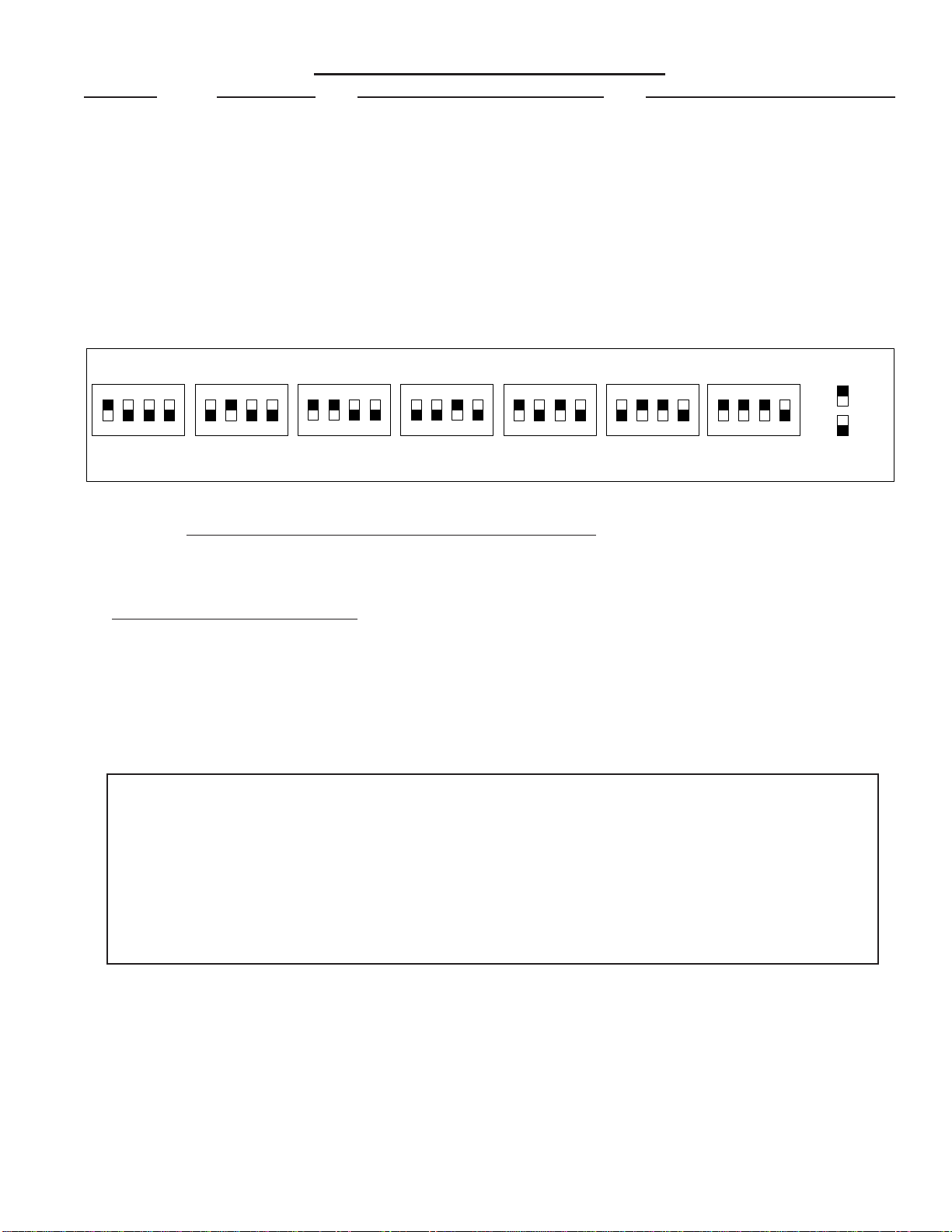
TABLE 1: Data Bus Address Switch Settings
ON
1234
ON
1234
ON
1234
ON
1234
Address1
ON
1234
ON
1234
ON
1234
Address2Address3Address4Address5Address6Address7LEGEND
ON
OFF
Data Bus Terminating Jumper JP1 – This is engages a 120 Ohm resistor for terminating the M1 RS-485 Data Bus. See Data bus wiring instructions before use.
ForDataBusType5Devices(SerialExpanders)theonlyvalidAddressesare1thru7andthereforethemaximumnumberofType5Devicesis7.
Mounting - Connections - Setting the Data Bus Address - Enrolling the Data Bus Device
1. Turn o the M1 Master Power Switch and unplug the Leviton VRC0P-1LW (vizia rf+3) before making any wiring connections.
2. Mount the M1XSLZW as close as possible to the Leviton VRC0P-1LW (vizia rf+3) . The RS232 Serial cord supplied by
Leviton is approximately 8 ft. DO NOT use an extension or attempt to make this cord any longer!
3. Follow the wiring recommendations in the M1 Installation Manual to connect the data bus terminals +12V, A, B, and Neg from
the M1 Control to the terminals on the M1XSLZW. It may be necessary to install an M1DBH or M1DBHR Data Bus Hub if
more than 2 homerun data bus cables are coming into the M1 Control.
4. Set the data bus address switches on the M1XSLZW to a value between 1 and 7 following the diagram below. Make sure the
address you select is NOT being used by any other data bus Type 5 (serial expander) device. Each switch has an OFF and
On position (binary value 0 or 1). The combination of these switches represents a decimal value of between 0 (all O) and 15
(all On).
5. Connect the Leviton VRC0P+3 Serial Interface to the M1XSLZW using the modular RS232 serial cable supplied with the
VRC0P+3. DO NOT use an extension or attempt to make this cord any longer!
6. Once all wire connections are complete plug the Leviton VRC0P+3 into a convenient AC Output that is NOT controlled by a
switch (Always On 24hours). Next, turn on the M1 Master Power Switch which will then supply power to the M1XSLZW.
7. Enroll the M1XSLZW to the M1 Control. REQUIRED! This is done either via a Keypad or ElkRP Software. From a Keypad
access the Installer level programming and select Menu 01-Bus Module Enrollment. Press the right arrow key to start the
enrollment. When complete press the right arrow (edit) key to view the results. The M1XSLZW shares the same bus type as
other serial expanders and will display as a "SerialPExpdr T5" followed by a specic address (Addr) number. Verify that the
address displayed matches the address selected in step 4 above.
Should it become necessary to replace a M1XSLZW then set the replacement unit to the same address as the old unit
and perform the enrollment process. To permanently remove any data bus device perform the enrollment process AFTER
disconnecting the device. This will help avoid a "missing device" trouble condition.
STEP 2 - Setting up the M1XSLZW
* * IMPORTANT - PLEASE READ * *
1) Elk does not recommend mixing (combining) Z-Wave devices with other lighting technologies (e.g. Insteon, UPB,
Zigbee, Lutron, etc.) on any installation. Potential interference, device ID overlap, and other issues can lead to unreliable
operation. If mixing of technologies cannot be avoided, the Installer must assume all risk and liability. Elk does not
endorse or support the mixing of Z-Wave and other lighting technologies.
2) Z-Wave Thermostats CANNOT BE MIXED (combined) with other Thermostat technologies or brands. I.E. Do not
mix hardwired Thermostats such as RCS RS485, HAI RS232, or Aprilaire RS485 on the same M1 panel with Z-Wave
Thermostats. If this advice is not followed AND Z-Wave Thermostats become mixed with hardwired Thermostats on the
same installation NO DATA will be displayed for the Z-Wave Thermostat(s).
TABLE 2: Diagnostic LED Indicator
Slow blink (1/2 sec.) = Normal communication with M1.
Rapid icker = Discovery Mode. The M1XSLZW is synchronizing with the VRC0P+3 to collect all current
data. This is automatically performed upon reboot or power up.
No blink = No communication with M1. Check the wiring with the M1 and that the device has power.
Table of contents
Other Elk Recording Equipment manuals


