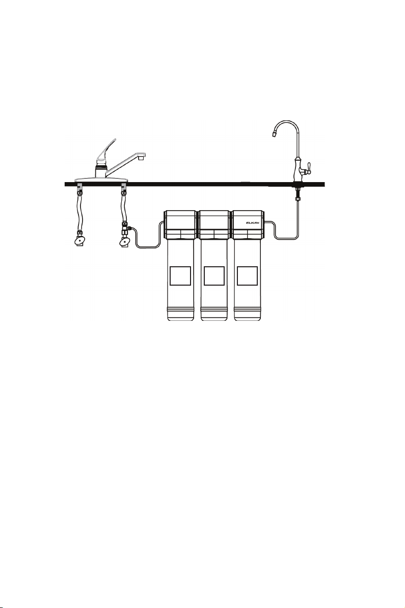
Filter Cartridge Replacement
1. Turn off the water at the tee ball valve and open the faucet to relieve pressure in the filter system.
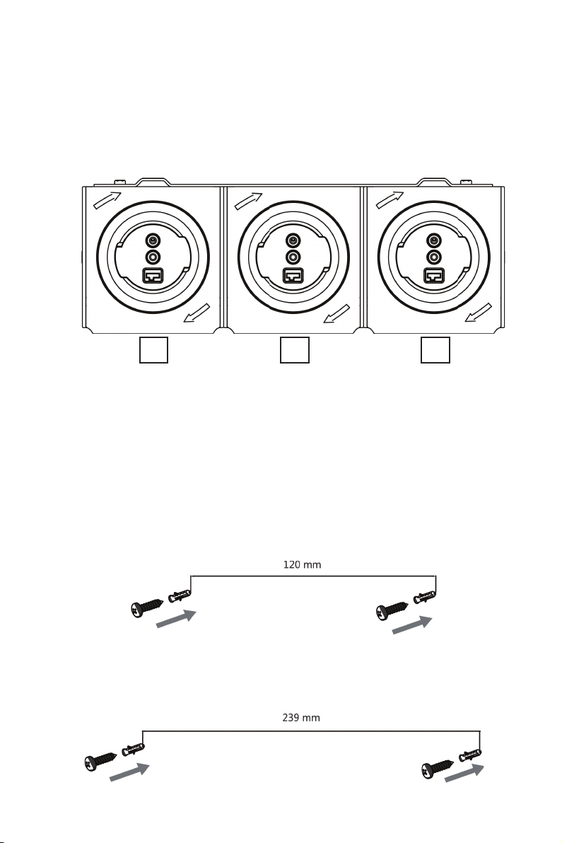
2. Unlock the filter cartridges by turning counter-clockwise.
3. Line up the ports, insert the cartridge, and turn clockwise to lock.
4. Reset the filter life.
5. Flush the system by allowing the water to run to drain for 10 minutes. It is normal for the water
to be cloudy with carbon and air during the flush time. After flushing the system is ready to use.
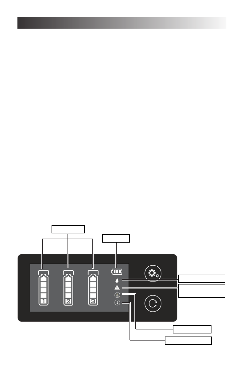
Name of filter component Recommended throughput Recommended replacement interval
PP fi lter cartridge 3-5t 3 months
MS filter cartridge 2-3t 6 months
UF filter cartridge 2-4t 24 months
Troubleshooting
LEAKS BETWEEN THE CARTRIDGE AND THE MANIFOLD:
1. Turn off the water at the tee ball valve and open the faucet to relieve pressure in the filter system.
2. Unlock the filter cartridges by turning counter-clockwise.
3. Line up the ports, insert the cartridge, and turn clockwise to lock.
4. Turn on the tee ball valve, close the faucet and inspect for leaks.
LEAKS AROUND THE FITTINGS:
1. Turn off the water at the tee ball valve and open the faucet to relieve pressure in the filter system.
2. While pulling the 1/4˝ plastic tubing with one hand, press in on the collar around the inlet and/
or outlet fi tting. Check to make sure that the plastic tubing is cut squarely and that it is not
scratched or crimped.
NOTE: If the plastic tubing is unevenly cut or scratched, cut off 10-20mm and re-install the tubing.
3. Turn on the tee ball valve, close the faucet and inspect for leaks.
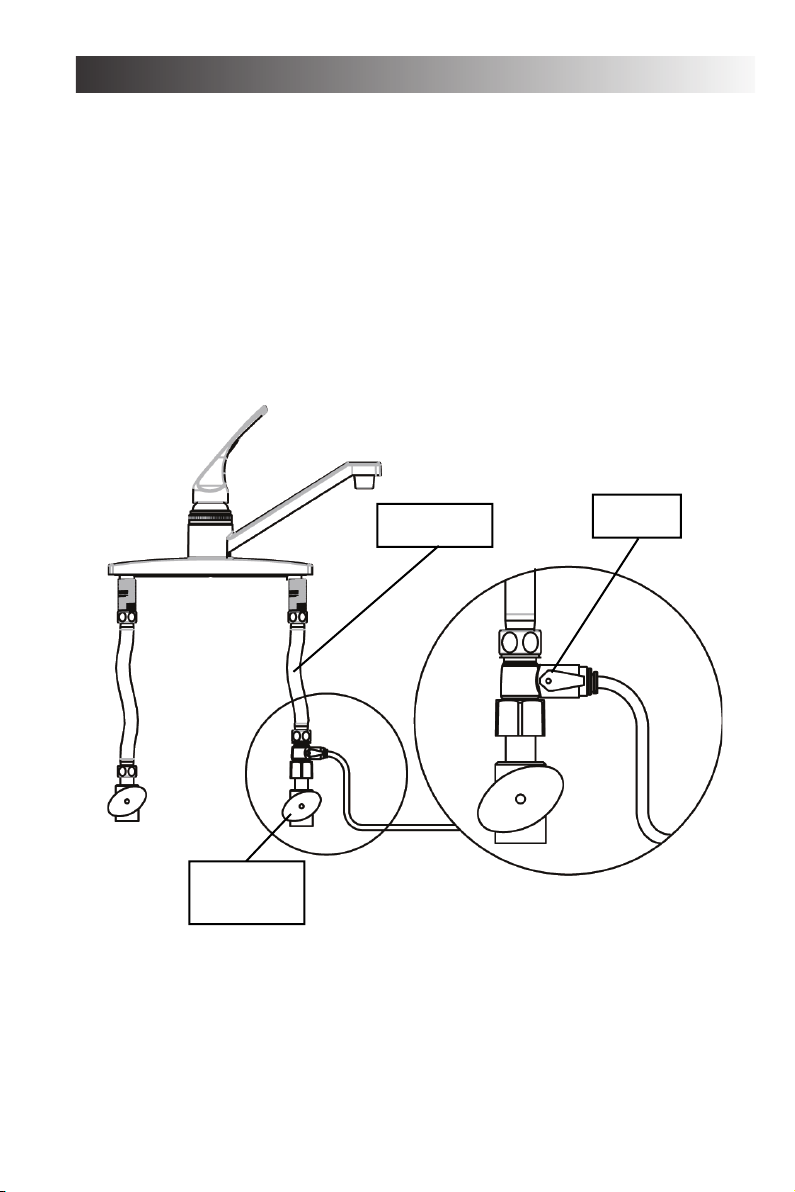
LEAKS AT THE TEE BALL VALVE:
1. Turn off cold water shut-off valve. Turn on the kitchen faucet to cold and dispensing faucet.
Allow all pressure to drain from line.
2. Locate the tee ball valve.
• If the plastic tubing is leaking, follow the previous steps (“Leaks around the fittings”).
• If the thread between the water supply adapter and the cold water line is leaking tighten more
securely.
3. Turn on the cold water shut off valve and close the faucets. Inspect for leaks.
THE ELECTRONIC DISPLAY IS NOT ON:
1. Remove the center manifold cover to access to back of the electronic display.
NOTE: The cover snaps may need to be pushed in with a screw driver at the back of the manifold.
2. Locate the flow meter wires and confirm that it is plugged into the display.
If you continue to have issues or if your issue is not listed here, please contact customer support.
Warranty
The Undermount Filter EFC22-A/EFU23-A/EFU23D-A is warranted to be free from defects in
materials and workmanship for a period of one year from date of installation.
Warranty is limited to repair or replacement of defective component.
Page 10
1000003973 (Rev. A - 05/17)
International Customer Care 630-575-4755 IntlCare@elkay.com