Elkay EFR2075D-A Instruction Manual

ELKAY Undermount Reverse Osmosis
Systems EFR2075D-A and EFR2075D-B
Please read all instructions, specifications, and precautions before
installing and using your filter system.
1000004000 (Rev A - 05/2017)Page 1

Page 21000004000 (Rev A - 05/2017)
PARTS LIST
• Filter Manifold
• Cover for Pump and CB Cartidge
• Filter Cartridges:
• Stage 1 CF (Replacement PN: EFR2-CF-A)
• Stage 2 Carbon Block (Replacement PN: EFR2-CB-A)
• Stage 3 RO (Replacement PN: EFR2-RO75-A)
• Tee Ball Valve
• ¼” Tubing – White ( Qty. = 3m)
• ¼” Tubing with Flow Restrictor Plug – Red (Qty. = 2m)
• Storage Tank
• Storage Tank Ball Valve
• Pressure Reducing Valve
• Tee fi tting
• Connector Clips (Qty. = 10)
• Transformer
• Installation Manual
SPECIFICATIONS
Manifold Assembly Dimensions 407 x 145 x 436mm
Storage Tank Ø251mm x 358.5mm
Inlet Pressure 0.1MPa~0.35MPa
Inlet Temperature 0.19L/min
Maximum Daily Output 284L
Storage Tank Volume6L
Power Supply Specification Input: 220V AC
Output: 24V DC
TOOLS REQUIRED
• Adjustable Wrench
• Utility Knife
• Towels
• Pan or Bucket

1000004000 (Rev A - 05/2017)Page 3
CF
Carbon Block
RO
Cover for Pump and CB
Cartridge
1/4” Tubing - White
1/4” Tubing - Red
W/ Flow Restricor Plug
Storage Tank
Connector
Clips
Transformer
Tee Ball Valve/
Tee Fitting
Storage Tank
Ball Valve

Notice
Do not use with water that is microbiologically unsafe or of unknown quality.
Filter cartridges must be protected against freezing temperatures, frost, snow, sleet, and ice.
Exposure to these elements can produce cracks and product failures.
Caution
This product has a limited service life. Because of the product’s limited service life and to prevent
costly repairs or possible water damage, we strongly recommend that the head of the fi lter be
replaced every ten years.
Caution
Turn off water supply to head and remove cartridges if it must be left unattended for an extended
period of time.
• For cold water use only. Do not use on hot water line.
• After prolonged periods of non-use (such as during a vacation) it is recommended that the
system be flushed thoroughly. Let water run for 5–6 minutes before using.
• The fi lters recommended for use with this system carry a limited service life. Changes in taste,
odor, color, and/or flow of the water being filtered indicate that the cartridge should be replaced.
• Make certain that installation complies with all state and local laws and regulations.
• Designed for residential use only.
Caution
Installation
1. Turn off the cold water shut-off valve. Then turn on the kitchen faucet to cold and allow all
water to drain from line.
2. Disconnect the cold water line from the cold water shut-off valve.
Note: If rigid plumbing pipe (metal or plastic) is used, you may need to shorten the pipe using
a hacksaw or pipe cutter to accommodate the tee ball valve.
3. Install the tee ball valve onto the supply valve and the cold water line to the top of the tee ball
valve.
Note: Do not over tighten the connections. Damage and/or leaks can occur if the connections
are over tightened.
Page 41000004000 (Rev A - 05/2017)
Tee Ball
Valve
Cold Water
Shut-off
Cold Water
Line

1000004000 (Rev A - 05/2017)Page 5
4. Remove the packaging from the fi lter cartridges. Install the cartridges into the fi lter manifold
by lining up the ports and rotating clockwise to lock them in.
Note: Remove black rubber plugs from filter ports before installing.
Note: Stage 1 (CF filter cartridge) is the left side of the manifold near the manifold inlet. The
RO cartridge goes on the right.
5. Install the cover over the CB cartridge and pump.
Note: The notches in the cover should be on the left side with the label facing to the front of
the system.
CBCF RO
Remove Black Plugs
6. Locate a position under the sink for the system to rest on the floor of the cabinet.
Note: Horizontal positioning of the filter manifold is required
Note:Allow space on the right and left side for the tubing to connect without becoming pinched.
Note: It is recommended that the tank be placed on the right side of the system.
7. Use the white ¼” tubing to connect the tee ball valve to the fi lter manifold inlet (INLET). Use
the utility knife to cut the tube to length and check for full engagement on quick connect fi ttings.
Note: A straight cut provides the best seal and prevents leaks.
Note: Wetting the end of the tube lowers the insertion force.
8. Use the white ¼” tubing to connect the dispensing faucet to manifold outlet (F)
9. Use the white ¼” tubing to connect the storage tank ball valve to the tank port (T) on the fi lter
manifold.
10. Using the red ¼” tubing, connect the end with the fl ow restrictor to the drain port (W) on the
fi lter manifold to the drain. The other end should be run to an open drain or drain saddle (not
included).
Note: There should be a 10cm distance between the end of the drain tube and the drain to
prevent sewage from being siphoned into the system.
11. Connect the transformer to the manifold (POWER) and plug into the electrical socket. The
buzzer will sound one time and the display will come on for 20s.
Note: Do not connect the system to a socket that is controlled by a switch.

Inlet
Side View
Outlet
Side View
Faucet
Drain
Storage
Tank
White 1/4”
Tubing
(INLET)
White 1/4”
Tubing
(F)
Red
1/4” Tubing
(W)
(Drain)
White 1/4”
Tubing
(T)
Power
Page 61000004000 (Rev A - 05/2017)

Initial System Startup
After installation, the system requires flushing before use.
1. Open the dispensing faucet. Then open the cold water shut-off valve and open the tee ball
valve. Inspect for leaks at the filter system and all fi ttings.
2. The system will fl ush automatically. It is recommended to fl ush the system for a minimum of
35 minutes after initial installation and after replacement of the RO membrane.
3. After fl ushing, turn off the faucet. Allow 30 minutes for the tank to fi ll. The machine set-up is
completed.
Electronic Display Operation
After the power is connected, the electron display will turn on. It will turn off after 20 seconds if no
buttons are pressed and there is no water being produced.
The electronic display will turn on when a button is pressed. It will turn off after 20 seconds if no
buttons are pressed and there is no water being produced.
When the system is producing water, the electronic display will turn on. The electronic display will
turn off when the system stops producing water.
Buzzer function:
• With any button pressed, the buzzer buzzes once.
• When the remaining filter life is low, the buzzer will sound once every 6s.
• During the fl ushing process and while producing water with the fi lter early warning the buzzer
sounds once every 6s.
Filter Life
The bars show the remaining life of the filters. The
scale bars will decrease with use and time.
Replacement due: the filter bar will be empty and
fl ashing.
Producing
Water
The producing water icon will be flashing when the
booster pump is enabled and
producing water.
Filter Early
Warning
If the remaining life of any level of filter has ≤2 bar,
the filter’s early warning icon will fl ash
and buzzer will sound once ever 6s.
Flushing
Prompt
Conditions for flushing startup: when the fi lter is
not used for 3 days or after reset of the filter life.
The flushing icon will display and fl ash during the
next use to warn the user to flush the fi lter. It can
be used after flushing.
1000004000 (Rev A - 05/2017)Page 7

TDS
When the system is producing water, the current
TDS of the product water will be
measured and displayed in 1PPM.
Setup Button Used to enter the setup screen.
Select Button Used to change the adjust values during
parameter setup.
Reset Button Used to reset the filter life from the setup screen.
Parameter Setup
Press and hold the SETUP button for 3s to enter the setup screen. At this time, TDS and PPM
icons will not be shown.
Setup Mode Filter Stage Code Default ValueValue Range
Time (Months)
106 01-12
212 01-18
324 01-36
Flow (Tons)
A08 01-12
B08 01-12
C08 01-12
Adjusted
Value
Filter Stage
Code
Example: 106 is Stage 1 time setup at six months.
• The setup starts with time setup at stage 1.
• Pressing the SETUP button will move to the next stage. Stage 3 time setup will move to Stage
1 flow setup.
• In the setup screen, pressing the SELECT button will increase the value by 1. When the value
reaches the upper limit, it returns to 1.
• To rest the fi lter life, move to that Stage in the setup screen and hold the RESET button for 5s.
The buzzer will sound once when the filter life is reset.
• The system will exit the setup screen after 10s with no buttons pushed.
Page 81000004000 (Rev A - 05/2017)

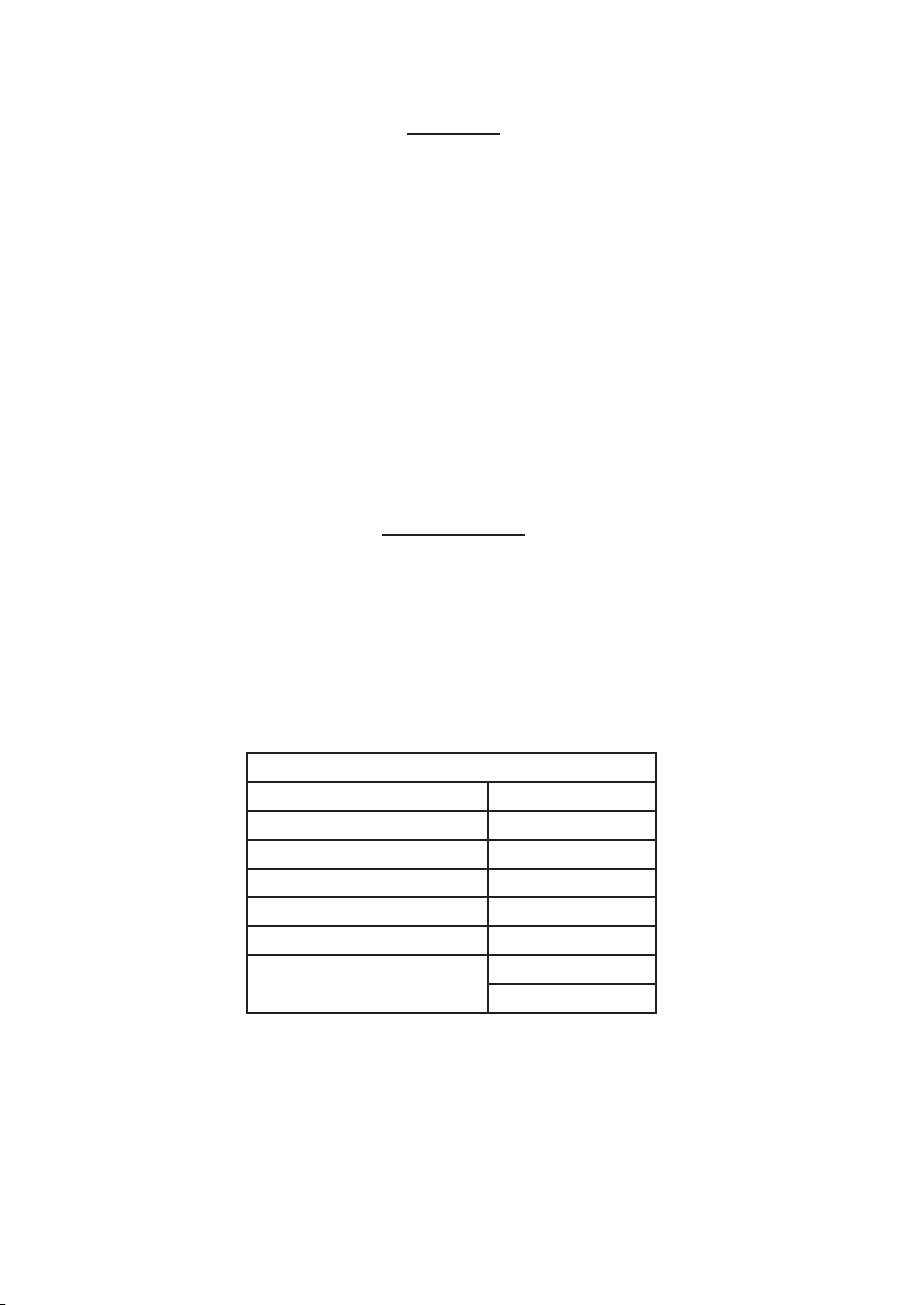
Filter Cartridge Replacement
Name of Filter Component Recommended Throughput Recommended Replacement
Interval
CF Filter Cartridge 8 Tons 6 Months
RO Membrane Cartridge 8 Tons 24 Months
CB Filter Cartridge 8 Tons 12 Months
1. Turn off the water at the tee ball valve and open the faucet to relieve pressure in the filter system.
2. Unlock the filter cartridges by turning counter-clockwise
3. Line up the ports, insert the cartridge, and turn clockwise to lock.
4. Reset the cartridge life and flush the system.
Troubleshooting
Leaks between the cartridge and the manifold:
1. Turn off the water at the tee ball valve and open the faucet to relieve pressure in the filter system.
2. Unlock the filter cartridges by turning counter-clockwise
3. Line up the ports, insert the cartridge, and turn clockwise to lock.
4. Turn on the tee ball valve, close the faucet and inspect for leaks.
Leaks around the fittings:
1. Turn off the water at the tee ball valve and open the faucet to relieve pressure in the filter system.
2. While pulling the 1/4˝ plastic tubing with one hand, press in on the collar around the inlet and/
or outlet fi tting. Check to make sure that the plastic tubing is cut squarely and that it is not
scratched or crimped.
Note:If the plastic tubing is unevenly cut or scratched, cut off 10-20mm and re-install the tubing.
3. Turn on the tee ball valve, close the faucet and inspect for leaks.
Leaks at the tee ball valve:
1. Turn off cold water shut-off valve. Turn on the kitchen faucet to cold and dispensing faucet.
Allow all pressure to drain from line.
2. Locate the tee ball valve.
• If the plastic tubing is leaking, follow the previous steps (“Leaks around the fittings”).
• If the thread between the water supply adapter and the cold water line is leaking tighten
more securely.
3. Turn on the cold water shut off valve and close the faucets. Inspect for leaks.
The electronic display is not on:
1. Reconnect the power supply and confirm that the system powers on.
The display does not turn on with the faucet:
1. Check the filter for blockage and replace if necessary.
2. Confirm the incoming water pressure is not too low.
If you continue to have issues or if your issue is not listed here, please contact customer support.
Warranty
The Elkay Undermount Reverse Osmosis System EFR2075D-A is warranted to be free from defects
in materials and workmanship for a period of one year from date of installation.
Warranty is limited to repair or replacement of defective component.
1000004000 (Rev A - 05/2017)Page 9
International Customer Care 630-575-4755 IntlCare@elkay.com

ﺢﺸﻤﻟاﺔﺸﺨلاﺒﺘﺴا
CF 8 6
8 24
8 12
1.. T
2..
3..
4..
لﺎﻋﻷاﯿﺨﺸﺘ
:
1.. T
2..
3..
4.. T
:
1.. T
2. . / 4/1
.
. 20-10 :ﺔﺤﻠﻤ
3.. T
:T
1.. . .
2..T
•.(" ")
•.
3.. .
:
1..
:
1..
2..
.
نﺎﻤﻀﻟا
EFR2075D-A ELKAY
.
.
(05/2017 -) 1000004000 9
IntlCare@elkay.com 630-575-4755 :

. 1
.
.
.
ﯿﯿﺎﻌﻤﻟا ﺒﻀ
. 3
.
()
10612 - 01
21218 - 01
32436 - 01
()
0812 - 01
0812 - 01
0812 - 01
. 1 106 :
•.1
•.1 3 .
•.1 .1 ""
•. 5 ""
.
•. 10
8 (05/2017 -) 1000004000

ةﻤلوﻷزﺎﻬﺠﻟا ﯿﻐﺸﺘ
.
1. .T .
.
2. 35 .
3.. . 30 .
ﻲﻨوﺘﮑﻟﻹاضﻌﻟا ﺔﺸﺎﺸﯿﻐﺸﺘ
20 .
.
20 .
.
.
.
:
•.
•. 6
•. 6
.
.
.
:
.
.
. 6
:
. 3
. .
(05/2017 -) 1000004000 7

() 4/1
4/1
(F)
(
W)
4/1
()
4/1
(
T)
6 (05/2017 -) 1000004000

(05/2017 -) 1000004000 5
4. .
.
. :ﺔﺤﻠﻤ
. ( ) 1 :ﺔﺤﻠﻤ
.
5.
. :ﺔﺤﻠﻤ
6..
:ﺔﺤﻠﻤ
. :ﺔﺤﻠﻤ
. :ﺔﺤﻠﻤ
7. .() T 4/1
.
. :ﺔﺤﻠﻤ
. :ﺔﺤﻠﻤ
8.(F) 4/1
9.. (T) 4/1
10. (W) 4/1
.( ) .
. 10 :ﺔﺤﻠﻤ
11. . ()
. 20
. :ﺔﺤﻠﻤ

رﺎﺨإ
.
.
.
ﻪﯿﺒﻨﺘ
.
.
ﻪﯿﺒﻨﺘ
.
•. .
• . ( )
. 6 -5
• / .
.
•.
•.
ﻪﯿﺒﻨﺘ
ﯿﻛﺘﻟا
1.. .
2..
( ) :ﺔﺤﻠﻤ
.T
3. T
.
T
. / . :ﺔﺤﻠﻤ
4 (05/2017 -) 1000004000
T

(05/2017 -) 1000004000 3
- 4/1
- 4/1
/T
T

2 (05/2017 -) 1000004000
ءاﺠﻷاﺔﻤﺌﺎﻗ
•
•
•:
•(EFR2-CF-A: ) 1
•(EFR2-CB-A : ) 2
•(EFR2-RO75-A: ) 3
•T
•(3 =) - 4/1
•(2 =) - 4/1
•
•
•
•T
•(10 =)
•
•
تﺎﻔﺼاا
436 ×145 ×407
358.5 ר251
0.35 ~ 0.1
/ 0.19
284
6
220 :
24 :
ﺔﺒﻠﻤﻟا تاودﻷا
•
•
•
•

ﯿدﻤضﺤﻟا ﻔﺴأﺒﺜﻤﻟاﻲﺴﮑﻌﻟاﺢﻀﺎﻨﺘﻠﻟ ELKAY زﺎﻬﺠ
EFR2075D-A & EFR2075D-B
.ﻪﻤاﺨﺘﺴاوهﺎﯿﻤﻟاﺢﯿﺸﺘزﺎﻬﺠ ﯿﻛﺘﺒﻗ تﺎﺎﯿﺘﺤﻻاوتﺎﻔﺼاﻤﻟاوتﺎﻤﯿﻠﻌﺘﻟاﻊﯿﻤﺠةءاﻗءﺎﺠﺒ
(05/2017 -) 1000004000 1
This manual suits for next models
1
Table of contents
Languages:
Other Elkay Water Filtration System manuals
Popular Water Filtration System manuals by other brands

Doulton
Doulton HIS installation instructions

Veolia
Veolia ELGA MEDICA-D 7 MKII US Operator's manual

DH Instruments
DH Instruments 1-2 IN. FILTER KIT instruction sheet

Pentair
Pentair STA-RITE AT 10 1-1,6A instruction manual

uv guard
uv guard SLT Series Installation and operation manual

Potterton
Potterton ZLF 160 installation manual