Elkron CT06 User manual

CT06
LBT80411
Installation manual
PSTN telephone communicator
DS80CT49-004B

CT062
Table of contents
1.0 General characteristics ............................................................... 3
2.0 Preliminary installation activities ................................................ 4
2.1 Devices required ...................................................................4
2.2 Removal microswitch installation/connection............................4
2.3 Fastening .............................................................................4
3.0 Installation ............................................................................... 5
3.1 Opening/closing the box .......................................................5
3.2 Product components .............................................................5
4.0 Description of LEDs and buttons .............................................. 6
4.1 Description of the LEDs .........................................................6
4.2 Description of the buttons .....................................................7
4.3 Description of the outputs ......................................................7
4.4 Telephone anomalie ..............................................................9
4.5 Cycle history.........................................................................9
4.6 Safety rules ..........................................................................9
4.7 Example of connection ..........................................................10
5.0 Operating principles.................................................................. 11
5.1 Alarm procedure ...................................................................11
5.2 Voice call cycle......................................................................11
5.3 Stopping the call cycle ..........................................................12
5.4 Answering machine and remote control function ..................... 13
5.5 Default settings ....................................................................15
5.6 Language selection................................................................16
5.7 Viewing system status...........................................................16
6.0 User programming .................................................................... 18
6.1 User Programming list ............................................................18
7.0 Engineer programming ............................................................. 19
7.1 Engineer programming list....................................................19
7.2 Telephone number programming list......................................20
7.3 Output switching menu ........................................................21
7.4 Answering service menu (for remote controls)........................ 22
7.5 Engineer code changing menu .................................................22
7.6 Call Test menu ......................................................................23
7.7 Vocal message programming menu ...........................................24
7.8 PSTN parameter programming menu .........................................25
7.9 Input programming menu ........................................................29
7.10 Output programming menu ......................................................30
7.11 Telephone number association / inputs .....................................31
7.12 Telephone number association / failure .....................................32
8.0 Technical specifications .............................................................. 33
9.0 Programming Tables ................................................................... 34
9.1 Association of phone numbers / networks / messages .............. 34
9.2 Programming telephone networks ............................................ 34
9.3 Inputs and outputs programming ............................................. 35

CT063
1.0 General characteristics
This manual contains instructions for installing and using Elkron communicators model CT06.
•3inputs
-2 programmable alarm inputs
-1 TC input
•5outputs:
-2 electrical FAILURE outputs
-3 outputs which can be switched by DTMF commands or
local keypad: 2 electrical and 1 relay
•12 telephone numbers (28 digits)
•Alarm methods:
-voice messages
•60 seconds integrated voice synthesis
•Remote control feedback (by voice messages)
•Non-volatile memory (operation ensured also during a black-
out)
•Answering service function
•Remote call barring (DTMF control)
•Skip outgoing message on PSTN line
•PSTN telephone line test
•System status menu
•User menu
•Engineer menu
•On-board alphanumeric keypad with 2-line 16-character
LCD
•6 system status and warning LEDs
•Anti-tampering protection
•12V 2.2 Ah battery housing
•Headphones for recording and listening the voice messages (provided)
•6 languages
•6 telephone standards

CT064
2.3 FASTENING
•Remove the electronic board from the supports to safely handle the plastic box only
without the risk of damaging the boards.
•Fasten the box to the wall with the devices provided (see figure below).
A
A
A
B
A
WALL FASTENING
HOLES
B
WIRE PASSAGE
ARRANGEMENTS
box bottom
1 2
34
2.0 Installation
2.1 OPENING/CLOSING THE BOX
B
B B B
2.2 REMOVAL MICROSWITCH INSTALLATION/CONNECTION.
1
1
2
2
8
8
7
7
6
6
3
3
4
4
5
5
12 3
Fit the plug in the
suitable seat and
adjust the screw
until it comes out
by 10mm
Place the microswitch
as shown in the figure Use 2 “TAMPER” plugs as
a support to connect the
microswitch wires

CT065
3.0 Description of LEDs and keys
3.1 DESCRIPTION OF THE LEDS
3.2 DESCRIPTION OF THE KEYS
OK key used to confirm
parameter modifications
during programming and to
start listening to and
recoding messages
Arrow keys used to scroll the
programming menu and select
the functions to be programmed
EXIT key used to quit the
programming menus
Number pad keys for entering
access code, telephone
numbers and selecting
programming parameter values
Key for accessing the SYSTEM
STATUS MENU (in combination
with number keys) and for
deleting telephone numbers
1
7
4
2
8
5
0
3
9
6
C
ABC
DEF
GHI
JKL
MNO
PQRS
TUV
WXYZ
+
NETWORK/BATTERY
ON = NETWORK OK
OFF = NO NETWORK
BLINKING = LOW BATTERY
TELEPHONE FAILURES
OFF = NORMAL
SLOW BLINK = FAILURE/MEMORY
FAST BLINK = FAILURE PRESENT
ALARM MEMORY
OFF = NORMAL
SLOW BLINKING = ALARM
INPUT STATUS
OFF = INPUT OK
ON = INPUT ALARM
OUTPUT STATUS
OFF = OUTPUTS OK
ON = SWITCHED OUTPUTS
TRANSMISSION STATUS
ON = PSTN- DTMF DIAL LINE SOCKET
BLINKING= PULSE SELECT (COUNTER)

CT066
4.0 Description of board and connections
LB ............ PSTN line input
LA ............ PSTN line input
PB ............ PSTN line output
PA ............ PSTN line output
1. + RIF ........ IN1 IN2 input closure reference (+12VDc)
2. IN1 ........... alarm input
3. IN2 ........... alarm input
4. IN3 ........... TC input
5. - .............. GND
6. + PWR ...... +12Vdc power input
7. - PWR ....... power input
8. - BAT ........ battery
9. + BAT ....... battery
10. U1............ failure electrical output
11. U2............ failure electrical output
12. U3............ switching electrical output
13. U4............ switching electrical output
14. C.
15. N.C. .......... U5 switching relay output
16. N.O.
17. Vaux+ ....... +12Vdc spare (Imax = 150 mA)
18. Vaux - ....... 0V
19. tamper protection
20. tamper protection
21. headset socket
4.1 DESCRIPTION OF THE BOARD

CT067
4.2 DESCRIPTION OF THE INPUTS
IN1 and IN2 ALARM INPUTS
•There are 2single-shot alarm inputs.
•They can be programmed as N.O. - N.C. - TERMINATED or NOT USED (see “Instal-
lation menu”).
•The inputs can be programmed individually as 24h/24h (always active and instanta-
neous) or subjected to ON status of the communicator (TC command, see IN3).
•An input subjected to ON status (AND TC) can be programmed as INSTANTANEOUS or
TIMED (5sec./15sec./30sec./60sec./90sec).
IN3 INPUT (TC)
•IN3 input is configured as a TC (Trigger Control) command. It can be programmed as
N.O., N.C. or TERMINATED. IN1 and IN2 switching will not be recognised and the alarm
communication procedure will not be activated if level +12Vdc (TC ON) is present on
IN3. If on the other hand the level is 0Vdc (TC OFF), the switching of inputs IN1 and IN2
will generate a cycle of telephone calls. This operation can be useful if the communicator
is connected to an Elkron alarm control unit with a TC programmed output that by
default provides a high level (+12V) when the system is off and a low level (0V) when it
is active. Connect input IN3 to output TC of the Elkron control unit to automatically
enable/disable alarm transmission according to the active/inactive status of the control
unit.
•A later transition from ON to OFF of the TC command, i.e. following a new activation of
the system, will cause the “alarm memory” to be cleared.
•NOTE: Conventionally, condition 0V = TC OFF and +12V = TC ON is provided when
the TC input is programmed as N.O. (normally closed).
4.3 DESCRIPTION OF THE OUTPUTS
U1 and U2 FAILURE OUTPUTS
•These electrical outputs are dedicated to signalling FAILURES. They normally output a
+12Vdc signal, which is down when the output is signalling. Two types of failures are
controlled, namely “TECHNICAL FAILURES” and “TELEPHONE FAILURES”.
•Output U1 is dedicated to “technical” failures. It switching indiscriminately for:
-Blackouts or external power supply under the minimum stated value for longer than 2
hours (terminals 6 and 7).
-Low battery, i.e. power under a threshold of 10.8Vdc for longer than 120 seconds.
Blackout/power back and low battery events are managed in the following way:
1. Blackout: the “MAINS/BATTERY” LED on the front panel goes out after approximately
10 seconds. After a 2 hour time-out, U1 switches to blackout and makes the techni-
cal failure calls to the voice enabled telephone numbers.
2. Power back: the “MAINS/BATTERY” LED lights up after approximately 10 seconds
and U1 is reset. No calls are made.
3. If the battery power drops under the 10.8V threshold, the “MAINS/BATTERY” LED will
blink, the U1 output will switch to low battery and the technical failure calls will be
made. U1 will be reset when power comes back but the “MAINS/BATTERY” LED will
continue blinking to indicate that the low battery event has been detected. This LED is
switched of manually by clearing the System Status menu memory. Note that low
battery status can only be detected during a blackout.
•Output U2 is dedicated to “telephone failures” and indiscriminately switches in the follow-
ing cases:

CT068
-No PSTN telephone line
This condition is determined by the negative outcome of the PSTN line test (see
paragraph 8.10). The output is reset if the telephone line is detected during the
following test.
-Absence of PSTN card
The communicator checks the presence of PSTN card. Card extraction will cause the
output to switch and PSTN fault to be displayed. Output return to rest status (recovery)
is by fitting the card again into to the communicator.
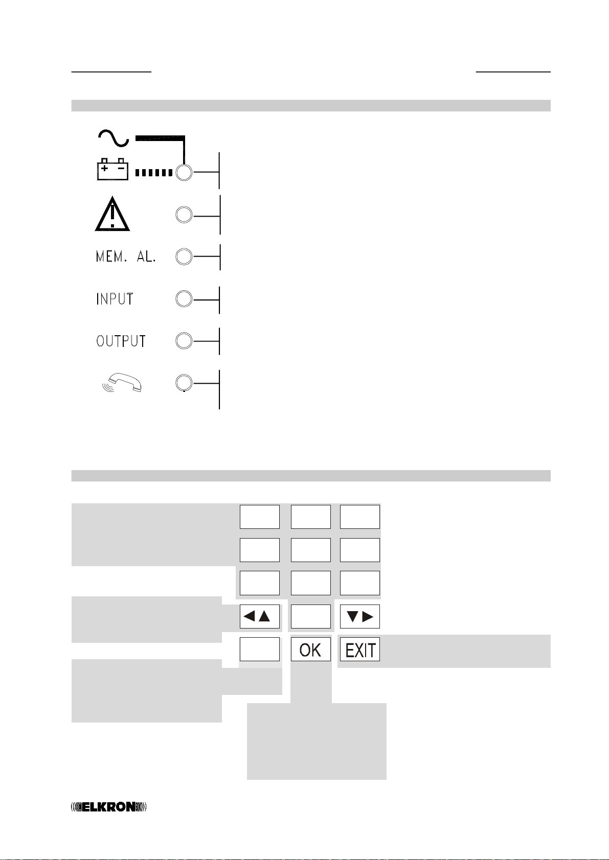
Telephone FAILURES are also signalled by the LED on the front panel which blinks fast.
The LED will blink slowly after the condition which caused the failure is restored to
indicate that the event has been stored in the memory.
The memory signal can be cancelled manually by means of “Clear Data” in the Wieving
System Status menu (see pag.20)
The probability of positive call cycle outcome is proportional to the number of pro-
grammed telephone numbers. For this reason, YOU ARE ADVISED TO PROGRAM MORE
THAN ONE TELEPHONE NUMBER.
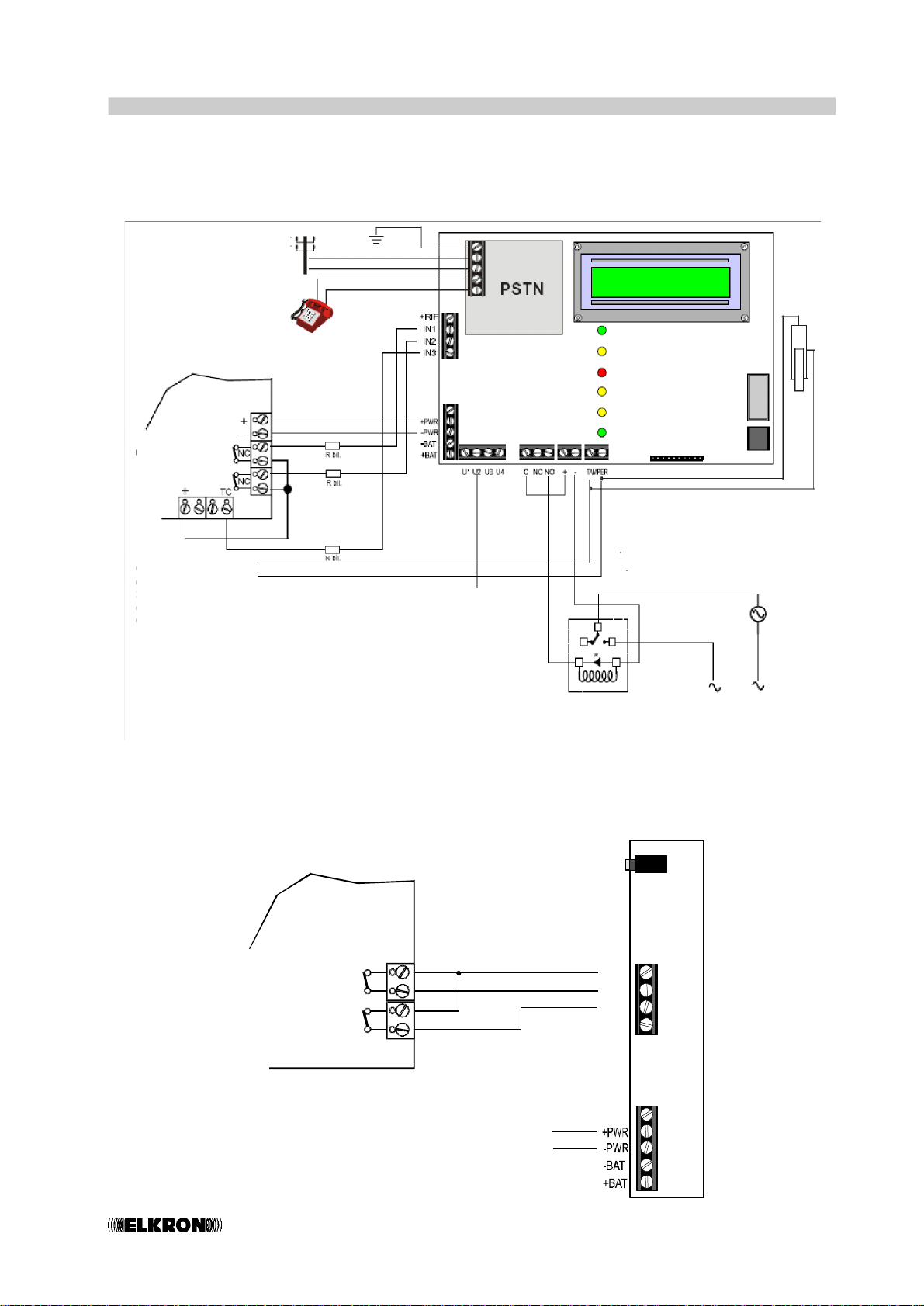
U3, U4, U5 OUTPUTS
•U3 and U4 outputs are electrical while output U5 consists of a free exchange C-N.C.-
N.O. relay. U3 and U4 present 0V when de-energised (+12V active). The relay dedi-
cated to U5 is de-energised. The outputs can be programmed as: Not Used, Associated
to inputs I1 and I2 or Controllable (remotely or locally by menu).
1. An output programmed as Not Used will be always de-energised.
2. An output programmed as Linked to an input (I1 or I2) will be activated according
to the associated input conditions. It can be programed as maintained or timed (5
sec/10 sec/30 sec/60 sec/90 sec).
•Associating an output to an input makes the output activate (switch) and return to de-
energised condition in different ways according to the type of associated input.
-If the associated input is 24h, the output will activated (switched to +12V) when the
associated input status changes from de-energised condition.
-Two cases are possible if the associated input is programmed as AND TC:
. With TC OFF, input status change will activate the associated output. Furthermore,
if the input is programmed as delayed, the associated output will be activated at
the end of the delay.
. With TC ON, input status change will be ignored. Consequently, the output will not
be activated.
-Resetting of an output can occur in different ways according to the programming:
·If the output is steady and associated to a 24h input, it will stay up until the user code
(or engineer code, where enabled) is entered by means of the keypad.
·If the output is steady and associated to an input in AND with TC, transition of
the TC to ON will instantaneously reset the output. Alternatively, this can be obtained
by entering the user code (or engineer code, where enabled) on the keypad.
·If the output is timed, it will reset to stand-by at the time-out also according to the
methods described for steady outputs (keypad codes and TC inputs) if waiting for
time-out is not required.
.The output will not switch if the associated input is programmed as Not Used.
3. If an output is programmed as Switchable, maintained or timed, refer to Chapter
5.4 “ANSWERING SERVICE AND REMOTE CONTROL OPERATION” for details. NOTE:
Only the status of “Switchable outputs” can be varied by means of the “Switch
Output ” menu.

CT069
4.4 TELEPHONE ANOMALIES
•The communicator, whenever is carrying out a call cycle (with answer control), is able to
check call outcome. A telephone fault is considered as such if more than 90% of the calls
of each cycle were not successful because of addressees’ missing answers.
•A return to normal situation (recovery) occurs if at next cycle at least 10% of the calls were
successful.
Fault memory signalling is only indicated in System Status menu.
•The memory signalling can be manually deleted through “delete data” operation from
System Status menu only if the fault was recovered with successful next cycle outcome.
NOTE: Fault recovery can be brought forward by manually sending a test call, provided that
the call is successful.
4.5 CYCLE HISTORY
•FAILURE and ANOMALY events are stored in an archive with the total number of cycles to
verify the reliability of the communicator in time. See “Viewing system status” for viewing
the cycle history.
4.6 SAFETY RULES
•In accordance with EN41003 standards, a SELV* 12V- power source (derived from
apparatus compliant with EN60950 standards) must be used to safeguard the device
and the communications network.
•U3, U4, U5 outputs where interfaced with hazardous voltage circuits (lights, boilers,
etc.) must be disconnectable by means of relays or similar devices. These must be
wired externally to the device, possible allocated in a specific electrical panel or enclo-
sure.

CT0610
4.7 EXAMPLE OF CONNECTION
•Example of not-balanced inputs referred to positive and U5 switchable output (relay)
controlling a 230Vac load.
•Example of outputs with contacts free from potential (e.g. technological devices) on
unbalanced inputs.
+RIF
IN1
IN2
IN3
CT06
Power Supply
Output 1
Output 2
Note: it is advisable to connect the plug with the electric system ground to ensure
better protection against overvoltage caused by weather events.
Control Panel
BURGLARYALARMOUTPUT
PANICALARMOUTPUT
Connect 24h input
in control panel to
manage
communicator
tamper protection
The relay must be wired out of
the communicator for safety
standard requirements
(*diode 1N4001-4004)
Connect with
the alarm control
panel “FAULT” input

CT0611
5.1 ALARM PROCEDURE
1. Alarm status is tripped when input I1 or I2 switches from de-engerised according to
the programmed mode (N.C., Balanced, N.O., 24h, AND TC, instantaneous or de-
layed). The “ALARM MEMORY” LED will blink.
2. At the same time, the communicator will send alarm signals (voice messages) to the
programmed telephone numbers associated with the alarm input.
3.The call cycle can be stopped locally by entering the user or installation code (where
enabled) on the keypad. If the input which generated the event is associated to the
TC, the call cycle can be stopped by a barring command received on input I3 (TC
ON). Note that the communicator can complete the call in progress during barring.
4. The procedure is repeated for all telephone number to which inputs are associated
(see “Input programming”).
5. The communicator will call each associated telephone number three times. If answer
check is programmed (PSTN), a telephone number which does not answer will not be
called back.
6. After ending the telephone cycle, the alarm memory LED will continue to blink and the
inputs generating the event can be viewed in the “SYSTEM STATUS” menu.
7. Stored information will be automatically reset at the next transaction of the TC input
from ON to OFF, i.e. following a new system activation or manually by means of the
“SYSTEM STATUS” menu.
5.2 VOICE CALL CYCLE
•After an alarm, a vocal call is made on each event-associated phone number, to which
basis message (with 10 sec. duration) is sent followed by message associated to specific
event relating to: inputs, or failures.Other specific messages will be added if other events
to which the telephone number which is receiving the call is associated occurs at the same
time.
•The voice message will be repeated three times to each telephone number. After this, the
call will be ended and the other programmed numbers will be called.
•A tone allowing the user who is listening to the message to enter the “Barring code” (12 in
DTMF, see paragraph 5.3 “STOPPING THE CALL CYCLE”) will be sent at the end of each
voice message. If the call cycle is not locked, the cycle will continue with the next number.
The programmed telephone numbers are called in sequence from the first to the last, for a
total of three cycles.
•In the case of tones and active answer check, call outcome will depend on line tone detec-
tion (see “Installation menu”, paragraph 7.8).
5.0 Operating principles

CT0612
BASIC
MESSAGE
SPECIFIC
MESSAGE
BEEP
WAIT
FORBARRING
BASIC
MESSAGE
SPECIFIC
MESSAGE
BEEP
WAIT
FORBARRING
BASIC
MESSAGE
SPECIFIC
MESSAGE
BEEP
WAIT
FORBARRING
10 s 5 s 0.5 s 5 s
10 s 5 s 0.5 s 5 s
10 s 5 s 0.5 s 5 s
WARNING AUTOMATIC CALL
FROM THE SMITH’S
HOME
BURGLAR
ALARM
BEEP
WAIT
FORBARRING
10 s 5 s 0.5 s 5 s
DIAL 12
CYCLE BARRED
Voice message structure
sent three times:
Example of barring:
5.3 STOPPING THE CALL CYCLE
•The call cycle can be stopped by dialling 12 in DTMF (called “Barring code”) on the tel-
ephone receiving the voice call.
•Voice messages can be barred as shown below.
•The call in progress and the remaining call cycle (voice and text messages) will be com-
pleted if the “Barring code” is entered.
•If the input that caused the alarm is subjected to TC, the call cycle in progress is barred
when the TC switched to ON.
•The call cycle can also be barred locally by means of the keypad by entering a valid code
(user code or ENGINEER code, where enabled).

CT0613
5.4 ANSWERING SERVICE AND REMOTE CONTROL FUNCTION
•Various devices can be switched on and off remotely (e.g. air conditioner, lights, irriga-
tion system, etc.) by sending DTMF commands to any telephone and switching the
communicator outputs which are programmed as remotely controllable (U3, U4,
U5). If enabled, the communicator will answer incoming calls at any time, except for
when it is making alarm calls. Therefore, the user who wishes to perform a remote control
operation shall call PSTN number and wait for its reply, which occurs after the programma-
ble number of rings (2-4-8), see para. 7.4.
•Answers are notified by a tone allowing the caller to dial the USER CODE (in DTMF) within
30 seconds. A confirmation tone will be heard after each digit. A sequence of three confir-
mation tones will be heard at the end of the code if the code is correct. Otherwise a long
error tone will be heard. Three attempts to enter the correct code can be made before the
call is ended.
•The remote control can be used to switch the required outputs (see sequence in the
following figure) after the code has been accepted. This operation requires a three-digit
code:
-5: defines the type of “output switching” command.
-3 or 4 or 5: defines the output number to be switched
-1 or 0 is used to activate or deactivate the required output.
The communicator will give priority to an alarm triggered during the remote control
procedure. No on/off commands will be accepted and a WRONG CODE BEEP will be
output. Hang up.
•Each remotely controllable output can be programmed as maintained or timed.
-Status changes follow the command if the output is maintained.
-The on command (1) will activate the output and the timer while the off command
(0) will anticipate the time-out (if this has not already occurred) if the output is timed.
•The user has one minute from code recognition to complete the remote control opera-
tions. If no codes are sent by this time-out, the communicator will end the call in
progress and clear the line.
•The communicator will send a short confirmation tone after receiving each remote
control. A longer tone will be heard in the case of the following errors:
- programmed output other than “remotely programmable”
- wrong code
•If the code is accepted, the communicator will send the voice message recorded by the
user to confirm implementation of the control.
•At this point, the user will need to enter the “5” code again to switch other
outputs (or the same output) at the end of the voice message
•SKIP ANSWERING MACHINE MESSAGE
Connect to the communicator as follows if an answering machine is fitted on the PSTN
line used by the:
-call the PSTN telephone number
-wait for a single ring tone
-hang up quickly
-call the number again
\-

CT0614
Call
PSTN number
n
Answer tone
COMMANDS TO THE
COMMUNICATOR SIGNALS FROM THE
COMMUNICATOR MEANING OF THE SIGNALS
CONNECTION OK
RECEIVED CODE DIGIT
0.5s
BEEP
n0.5s
BEEP
n0.5s
BEEP
n0.5s
BEEP
n0.5s
BEEP
n0.5s
BEEP
Send six-digit
user code
(default
code
111111)
0.5s3 BEEPS CORRECT CODE
RECEIVED CODE DIGIT
RECEIVED CODE DIGIT
RECEIVED CODE DIGIT
RECEIVED CODE DIGIT
RECEIVED CODE DIGIT
BEEEEP WRONG CODE
1
2
5RECEIVED
0.5s
BEEP
Send code 5
3
3
Send code
corresponding
to output to
be switched *
OR
OR
(repeatprocedurefrompoint 2)
RECEIVED
0.5s
BEEP
44
5
OR
0
Send code :
1= on
or
0= off
51
OR 0.5s3 BEEPS COMMAND
DONE
+ ASSOCIATED VOICE
MESSAGE
*More than one output can be switched (or the same output more than once) during the
same call. Simply repeat the following operations sequence:
for each output to be switched. 345

CT0615
5.5 DEFAULT SETTINGS
Input status
IN1 = normally closed, subjected to TC, instantaneous
IN2 = normally closed, subjected to TC, instantaneous
IN3 (TC) = normally closed
Output status
U3 = deactivating, switchable, maintained
U4 = deactivating, switchable, maintained
U5 = deactivating, switchable, maintained
Input/telephone number/message type association
IN1 = 1° 2° 3° 4° 5° 6° VOICE MESSAGE
IN2 = 7° 8° 9° 10° 11° 12° VOICE MESSAGE
Failure/telephone number/message type association
Failure = 6th ...................VOICE MESSAGE
PSTN parameters
Country: Italy
Dialling method: MF
PBX derivation: off
Tone check: off
Answer check: off
PSTN line test: off
Answering service (for remote controls)
Off
User code
Code 111111
Engineer code
Code 000000 (enabled)
RESETTING DEFAULT PARAMETERS
To return the communicator to default parameters:
1. Disconnect power (and battery, where present).
2. Reconnect power. The buzzer will beep.
3. While the buzzer is beeping, press and
3
DEF
at the same time. Wait for the
buzzer to sound continuously and start beeping faster. The message
DEFAULT PARAMETERS will appear on the display when the procedure is over.

CT0616
5.6 LANGUAGE SELECTION
•The interface language can be selected in any condition without needing to enter a
code. Simply press “C” followed by 9. The languages will be displayed cyclically each
time the button is pressed. Either press to quit or wait for the one minute time-
out.
INPUTS NOT QUITTED
(e.g. Input 1)
ALARM MEMORY
(e.g. Input alarm 2)
CLEAR ALARM MEMORY AND
NETWORK/BATTERY FAILURE
WARNING LEDS
5.7 VIEWING SYSTEM STATUS
•The “SYSTEM STATUS” menu can be accessed in any condition without entering a code. Simply
press “C” followed by a number key (1,2,3,5,7,8,9). Either press to quit the menu or wait
for the time-out (one minute).
IN. Not QUITTED
IN.: 1
alarmmemory
IN.: 2
CLEAR alarm mem.
IN.:
BUTTONS TO
PRESS LANGUAGE
FRENCH
GERMAN
DISPLAY
TRANSMETTEUR
RTC
COMMUNICATOR
PSTN
KOMMUNIKATOR
PSTN
SELECT LANGUAGE
COMUNICATORE
PSTN
C
+
9
WXYZ
+
9
WXYZ
+
9
WXYZ
+
9
WXYZ
+
9
WXYZ
+
9
WXYZ
ENGLISH
SPANISH
COMUNICADOR
PSTN
PORTUGUESE
COMUNICADOR
LINEA FIXA
BUTTONS TO
PRESS EVENT TYPE
DISPLAY
C
+
1
C
+
2
ABC
C
+
2
ABC
+
2
ABC

CT0617
SWITCHED OUTPUTS
ANOMALY WARNING PRESENT
(see par. 4.4)
outputs on
U : 3 - 4 - 5
CALLS LOG
CYCLE KO: 0/000
PSTN KO 000/000
PSTN TEST KO: OOO
CLEAR DATA
OK/EXIT ?
CT06
V 1.00
AT EACH PRESSURE OF THE KEY 7
APPEAR THE FOLLOWING VISUALIZATION
CYCLES WITH ANOMALIES/TOTAL CYCLES
CALLS WITH ANOMALIES/PSTN CALLS
MADE
“NO PSTN LINE” FAILURE
COUNTER RESET COMMAND (ACTIVE ONLY
WHEN FAILURE AND ANOMALY CONDITIONS
HAVE BEEN RESTORED) AND TELEPHONE
FAILURE INDICATOR LED
BUTTONS
TO PRESS EVENT TYPE
DISPLAY
C
+
3
DEF
C
+
5
JKL
+
5
JKL
C
+
7
PQRS
+
7
PQRS
+
7
PQRS
+
7
PQRS
+
7
PQRS
C
+
call outcom
t1 xmmm---
call outcom
t2 xmmm---
LASTCYCLEHISTORICAL RECORDING
WITH INDICATION OF CALL OUTCOME
ASSOCIATEDTO PHONENUMBER
NEXTNUMBER
PSTN ANOMALY
SOFTWARE RELEASE (BOARD)
INDICATION OPERATION CONDITIONS TELEPHONE LINE TONES CALLOUTCOME
XTone control enabled Selection tone absent Call not made
or unavailable
STone control enabled and Free tone absent Only selection made
answer control enabled (silence after selection)
OTone control enabled and/or Busy tone Call not made
answer control enabled
NTone control enabled and Free tone present and Call not made
answer control enabled answer not made
RTone control enabled and Free tone present and Call made with
answer control enabled answer made message
MTone control enabled Free tone acknowledged Call made with
message
MTone control disabled Not occurring Call made with
message
BDuring stop code wait step DTMF tones of stop code 12 Stopped cycle
MANAGING CALLS OUTCOME (
C
+
5
JKL
)

CT0618
6.0 USER PROGRAMMING
NOTE: An alarm event occuring during programming will be signalled by means of the LEDs
on the panel. The respective outputs will switch. No calls will be made because the system
is being supervised at the time.
6.1 USER PROGRAMMING LIST
Enter the 6-digit user code x-x-x-x-x-x (default 111111)
Press to scroll the menu forwards
Press to scroll the menu backwards
Press to quit the menu
20
21
23
24
page
pag.e
page
page
22
page
22
page Access to the installation menu will
be disabled once the user code is
entered.
USERMENU
TELEPHONE NR.
USERMENU
SWITCH OUTPUT
USERMENU
CODE CHANGING
USERMENU
CALL TEST
USERMENU
VOCALMESSAGES
USERMENU
ANSWERINGPROG.
USERMENU
ENGINEER ENABLED ENGINEER
ENABLED ?

CT0619
7.0 ENGINEER PROGRAMMING
The telephone communicator is programmed by means of an INSTALLATION MENU.
Access to the menu must be authorised by the user (see USER MENU-ENABLE ENGINEER
procedure).
NOTE: An alarm event occuring during programming will be signalled by means of the
LEDs on the panel. The respective outputs will switch. No calls will be made because the
system is being supervised at the time.
7.1 ENGINEER PROGRAMMING LIST
Enter the 6-digit user code x-x-x-x-x-x (default 000000)
20
21
22
23
29
30
31
32
page
page
page
page
page
page
page
page
22
page
25
page
CT11-Monly
24
page
ENGINEER MENU
TELEPHONE NR.
ENGINEER MENU
SWITCH OUTPUT
ENGINEER MENU
CODE CHANGING
ENGINEER MENU
CALL TEST
ENGINEER MENU
ANSWERINGPROG.
ENGINEER MENU
VOCALMESSAGES
ENGINEER MENU
INPUT PROGRAM.
ENGINEER MENU
OUTPUT PROGRAM.
ENGINEER MENU
ASSOC.INP.-PH.NR
ENGINEER MENU
ASSOC.FAULT-PH.NR
ENGINEER MENU
PSTN MENU

CT0620
7.2 TELEPHONE NUMBER PROGRAMMING MENU
This menu is used to programme/edit the telephone numbers which will be dialled
automatically by the communicator following an alarm. Up to twelve numbers can be
programmed, maximum 28 digits each.
EXAMPLE
to scroll numbers forwards
to scroll numbers backwards
EXAMPLE
to confirm the
selected number
to confirm
programmed
number
Use keys 0-9 to enter the required
telephone number digits.
Press to include a 2 seconds pause
during dialling.
To edit a telephone number, position the
cursor on the digit to be changed by
pressing and enter the new
digits.
Press
C
to delete the entire number..
Press
0
+for at least one second to
enter the international prefix (+)
Press
7
PQRS
for at least one second to enter
*.
Press
9
WXYZ
for at least one second to enter
#.
to return to
telephone number
programming
ENGINEER MENU
TELEPHONE NR.
TELEPHONE NR.
n01: TELEPHONE NR.
n02: TELEPHONE NR.
n03:
TELEPHONE NR.
n12:
n12:012139282112
TELEPHONE NR.
n 12: 0121 39282112
Other manuals for CT06
1
Table of contents
Other Elkron Cell Phone manuals