Ellab RL4512 User manual

ellab.com
IM5984
RL4512 Dual Channel
CO2and Temperature
Sensor Unit
User Guide

Intentionally Left Blank

IM5984
RL4512 CO
2and Temperature Sensor Unit
Instruction Manual
Doc No. IM5984 - 3 Page 1 of 20 ellab
.com
Contents
1Introduction......................................................................................................................... 2
1.1 Pre-requisites......................................................................................................................................2
2The RL4512 Sensor Unit.................................................................................................... 3
2.1 Sensor Unit Battery...........................................................................................................................3
2.2 Mounting the Sensor ........................................................................................................................5
2.3 Radio Testing Dongle.......................................................................................................................5
2.4 Compliance .........................................................................................................................................5
3Setting up the RL4512 Unit with EMS ............................................................................. 6
3.1 Entering a Sensor/Probe’s Calibration Settings into EMS versions 1.0.9 and later.........6
3.1.1 Setting Alarms ............................................................................................................................ 12
3.2 Synchronising Sensors/Unit ......................................................................................................... 12
3.3 Merging Collected Data................................................................................................................. 14
Contact Information .........................................................................................................................19
Document History ...........................................................................................................................20

IM5984
RL4512 CO2and Temperature Sensor
Unit
Instruction Manual
ellab.com Page 2 of 20 Doc No. IM5984 - 3
1Introduction
This Document details how to configure the RL4512 CO2and Temperature Sensor Unit from
Ellab Monitoring Solutions Ltd for use in conjunction with the EMS application.
The RL4512 Unit is a Dual Channel Transmitter with channels for CO2and Temperature data
inputs from their respective sensors/probes.
The RL4512 Unit also has an on-board Data Logging facility. This facility can provide a data
backup capability in the event of a transmission or power failure or other interruption to the
flow of data from the Unit to EMS.
•Data is transmitted/uploaded to EMS from the Unit at defined Transmission Intervals,
either directly or via an SR2 Controller.
The current CO2and Temperature values, battery voltage and, optionally, the Alarm Status are
also displayed on the Unit’s LCD screen.
1.1 Pre-requisites
You will need the following to enable communication between EMS and the RL4512 Unit:
•Y055 USB lead.
•EMS application installed on a PC/Server.
•EMS Remote Management Tools
If the RL4512 Unit can be physically connected to the PC/Server with EMS installed or if
EMS is installed on a Virtual Machine (VM) or a Remote Server.
•Upgrade Disk
Installations running EMS Version 1.7.0 or lower must run this disk and follow the
instructions in the ReadMe.txt file before adding the Sensor Unit to EMS.

IM5984
RL4512 CO
2and Temperature Sensor Unit
Instruction Manual
Doc No. IM5984 - 3 Page 3 of 20 ellab
.com
2The RL4512 Sensor Unit
Figure 1
RL4512 Unit fitted with CO2and Temperature/Thermistor probes
2.1 Sensor Unit Battery
WARNING!
The RL4512 Series Sensor is powered by a 12V mains power supply which MUST remain
connected during normal operation.
When the Unit is not in use, the Battery Link, located on the Unit’s PCB, MUST be moved to
the position shown in Figure 2 below to disconnect the battery and prevent it discharging.

IM5984
RL4512 CO2and Temperature Sensor
Unit
Instruction Manual
ellab.com Page 4 of 20 Doc No. IM5984 - 3
Disconnected
Connected
Figure 2 - Battery Jumper Link
The Unit’s internal battery is ONLY provided as a reserve backup power supply to prevent
the RL4512 from losing logged data during the following operations, which may require the
Unit to be disconnected from the mains supply:
•Initial setup of the Unit.
•Downloading logged data following a transmission or power failure.
•Any change of the Unit’s configuration.

IM5984
RL4512 CO
2and Temperature Sensor Unit
Instruction Manual
Doc No. IM5984 - 3 Page 5 of 20 ellab
.com
Note: The internal battery is soldered in and is not replaceable by the customer. If the battery
becomes discharged, the Logging functionality will no longer work and the Unit will
have to be sent back to Ellab Monitoring Solutions for battery replacement.
2.2 Mounting the Sensor
A wall-mounting bracket is available for the RL4512 Unit (Code: Y119). It comprises a metal
strip which is fitted to the wall.
•To mount the RL4512 Unit on the bracket, line up the slots on the back of the Unit with
the tabs on the bracket and click the Unit into place.
•To remove the RL4512 Unit from the bracket, gently press the tag at the bottom of the
Unit’s case towards the wall, using a small screwdriver or similar, and lift the Unit free.
2.3 Radio Testing Dongle
This is an optional plug-in device (Code: Y058).
When connected to the RL4512’s USB socket, it overrides the Unit’s configured Transmit
Interval and forces the Unit to send a transmission every five seconds.
2.4 Compliance
The RL4512 Unit has been designed to comply with the RoHS and WEEE EU Directives and
carries the CE mark.
IM5984
RL4512 CO2and Temperature Sensor
Unit
Instruction Manual
ellab.com Page 6 of 20 Doc No. IM5984 - 3
3Setting up the RL4512 Unit with EMS
For information on the addition of the RL4512’s details to EMS, please refer to the EMS Online
User Guide, in particular the section System Configuration - Sensors:
http://www.help.emsprocloud.com/index.html?system-configuration-sensors.html
•The RL4512 Unit should be added as a CO2/Thermistor sensor.
Note: Default Temperature Calibration values are already configured/entered into the Unit
and will not need changing.
3.1 Entering a Sensor/Probe’s Calibration Settings into EMS versions 1.0.9 and
later.
Note: For details on entering Calibration Settings into EMS prior to Version 1.0.9, please
refer to Appendix A.
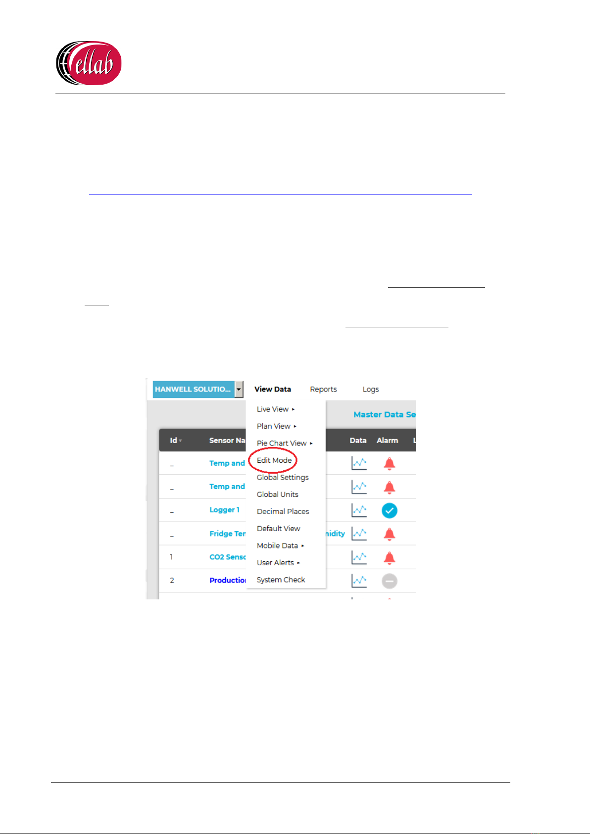
1. Select Edit Mode from the main View Data menu. See Figure 3 below:
Figure 3
•The Edit Mode window is displayed. See Figure 4 overleaf:

IM5984
RL4512 CO
2and Temperature Sensor Unit
Instruction Manual
Doc No. IM5984 - 3 Page 7 of 20 ellab
.com
Figure 4
•By default, the Edit Mode window for the Zone at the top of the left-hand menu is
displayed.
•To display another Zone's Edit Mode window, click on the entry for the required
Zone in the left-hand menu. For an example, see Figure 5 below:
Figure 5

IM5984
RL4512 CO2and Temperature Sensor
Unit
Instruction Manual
ellab.com Page 8 of 20 Doc No. IM5984 - 3
Note: Edit Mode is only available if you have the correct access Permissions.
If you do not have the correct access Permissions the following message window will
be displayed. See Figure 6 below:
Figure 6
2. Either:
i. In the left-hand list of the Zone's Edit Mode window, click on the small 'arrow'
symbol to display a list of the Sensor Units associated with the Zone. See Figure 7
below:
Figure 7
ii. In the left-hand list, click on the required R4512 Series Sensor Unit’s icon:
Or:
In the table in the Zone's Edit Mode window, click on the required R4512 Series Sensor
Unit’s name in the Sensor Name column. See Figure 8 overleaf:

IM5984
RL4512 CO2and Temperature Sensor
Unit
Instruction Manual
ellab.com Page 10 of 20 Doc No. IM5984 - 3
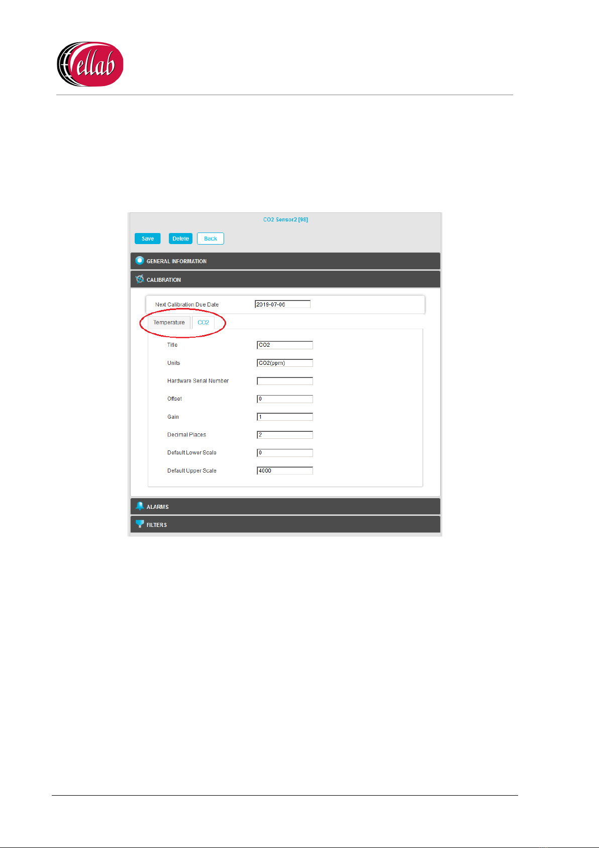
3. Click the on the Calibration field to expand the Calibration pane for the selected R4512
Series Sensor Unit.
•The Calibration pane will display separate tabs for the Sensor Unit’s Temperature
and CO2channels.
See Figure 10 below:
Figure 10
4. Click on the CO2tab and:
i. Enter the date that the next Calibration is due into the Next Calibration Due Date
field, in the format:
YYYY-MM-DD
∗If the Sensor Unit has just been added to the System, you will notice that the
default date on the form will be one year from the date that the Sensor Unit
was added.
∗The normal Calibration period is one year.
∗A good rule of thumb would be 12 months for environments that are either
contaminated or have consistently high operating humidities.
IM5984
RL4512 CO
2and Temperature Sensor Unit
Instruction Manual
Doc No. IM5984 - 3 Page 11 of 20 ellab
.com
Where the environments are uncontaminated and average humidities are
mid-range, then every 24 months would be acceptable.
ii. Enter or edit any other CO2Calibration parameter values as required.
∗The Offset and Gain values for the supplied Vaisala CO2sensor/probe are
listed in the CH 1 column of the table at the top of the Box Insert.
∗For more detailed information on Sensor Unit calibration parameters, please
refer to the Online Manual:
http://www.help.emsprocloud.com/index.html?calibration-general.html
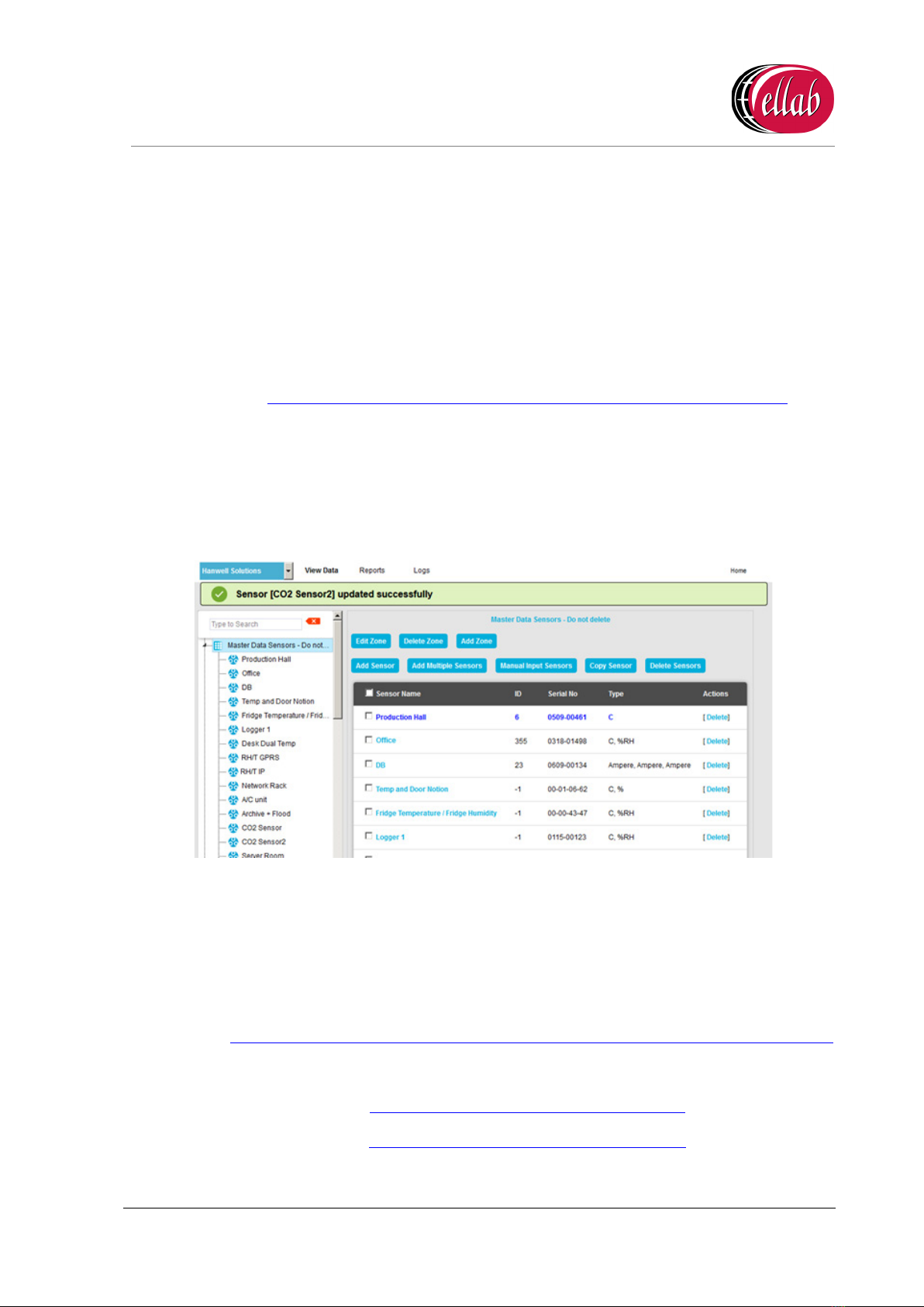
5. When you are happy with the new date select Save.
•Click on the Back button to cancel any changes to the Next Calibration Due Date.
•If the Update has been successful, you will be returned to the Zone's Edit Mode window
and the following message will be displayed. See example in Figure 11 below:
Figure 11
6. Repeat Steps 2 -5 for all required R4512 Series Sensor Units.
Note: Should you wish to carry out your own calibration of the CO2probe, please refer to
both the EMS Online User Guide:
http://www.help.emsprocloud.com/index.html?calibration-management-tools.html
and the following links which are also listed on the Box Insert:
http://pd.hanwell.com/Cal-linear-sensor.xls
http://pd.hanwell.com/Cal-linear-sensor.zip
7. Repeat Steps 2 -7 for all required RL4512 Units.

IM5984
RL4512 CO2and Temperature Sensor
Unit
Instruction Manual
ellab.com Page 12 of 20 Doc No. IM5984 - 3
3.1.1 Setting Alarms
To set Alarm Parameters and Levels, refer to the following section in the EMS Online User
Guide:
http://www.help.emsprocloud.com/index.html?levels.html
3.2 Synchronising Sensors/Unit
The Synchronise process:
Sets the Physical Transmit ID of the device.
•If the Physical Transmit ID listed in the Unit does not match the ID of the Sensor that you
are trying to synchronise with, then the ID listed in the Unit’s memory will change to
what is set on the Sensor you are synchronising with.
And
Takes the following Sensor Calibration settings for the selected RL4512 Unit and loads the
Calibration and Alarm settings from the EMS Database into the Unit:
•The CO2setting calculated from the Offset and Gain values entered as outlined in
Section 3.1 above.
•The default Temperature values.
To Synchronise a Sensor:
1. Ensure that the RL4512 Unit is connected to the PC/Server running EMS via the supplied
Y055 USB lead.
2. Open the EMS Remote Management Tools application.
•EMS Remote Management Tools provide an HTTP link to data in the EMS
database, allowing you to synchronise an RL4512 Unit when using EMS installed
on a Virtual Machine (VM) and also provide a physical link to the database when it
is possible to connect the RL4512 Unit directly to the PC with EMS installed via the
YO55 USB lead.
Refer to the following sections in the EMS Online User Guide:
http://www.help.emsprocloud.com/index.html?EMS-remote-management-tool.html
3. Select the CO2Sensor from the EMS Management Tool's/EMS Remote Management
Tools' EMS Management window.
4. Right click on the selected Sensor and select Sync Selected Sensor from the displayed
menu.
•The EMS Synchronise USB Sensor Vx.x window is displayed. See Figure 12
overleaf:
IM5984
RL4512 CO
2and Temperature Sensor Unit
Instruction Manual
Doc No. IM5984 - 3 Page 13 of 20 ellab
.com
Figure 12
Note: The sensor selected must match the Physical Device or the program will not
complete.
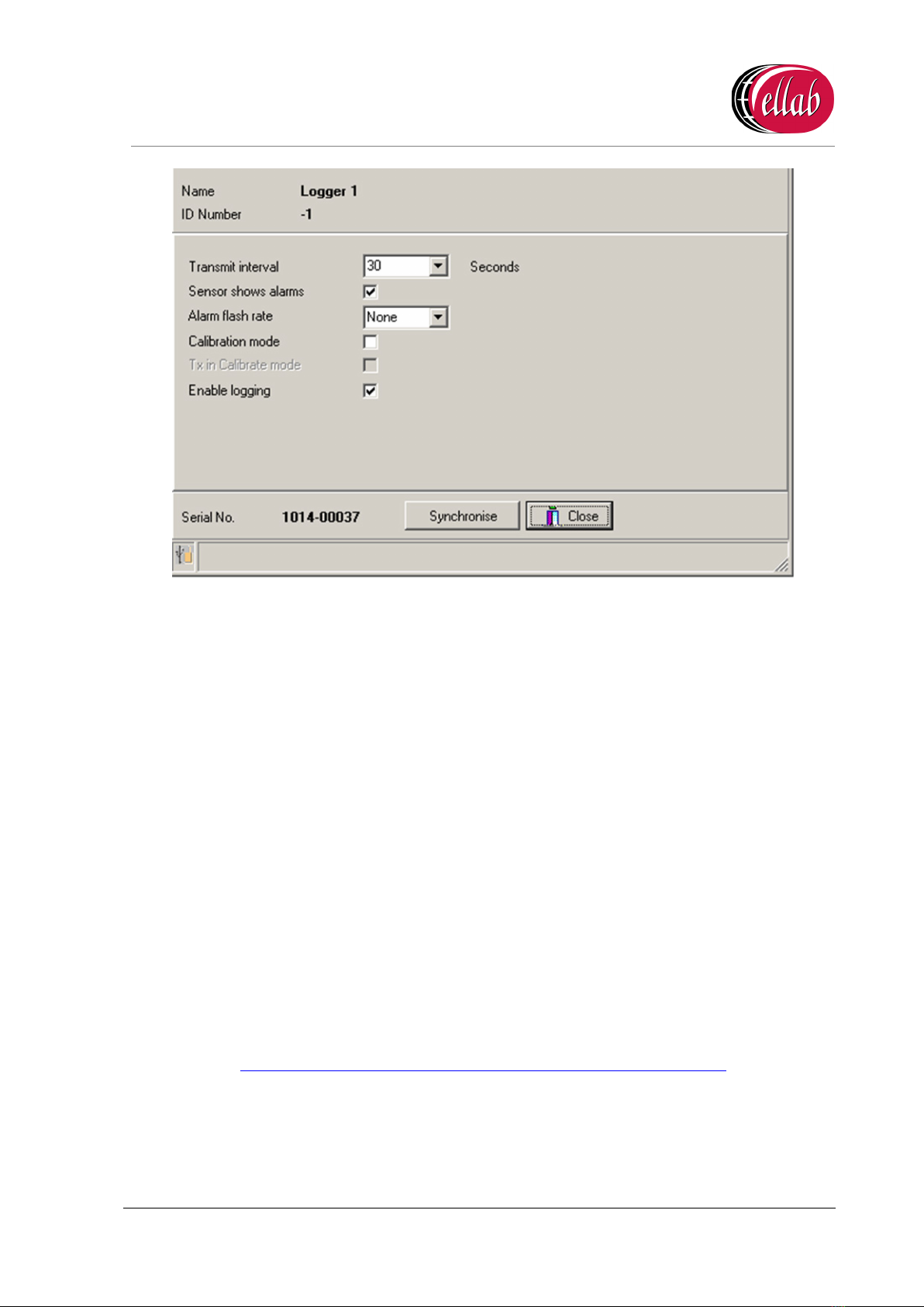
5. Select the required Transmit (TX) interval from the Transmit interval drop-down list (60
seconds is recommended for Calibration).
•The EMS Synchronise USB Sensor Vx.x window completes loading and all of the
window’s fields are populated.
6. Click the Synchronise button and follow the instructions given until it reports that the
Synchronisation is complete.
•The Sensor's display should now show the same value as displayed in EMS.
7. Close the window to finish Synchronisation and update the EMS database.
8. Repeat Steps 1 - 7 for all RL4512 Units to be added.
•Refer to the following section in the Online EMS User Guide for information on Viewing
Sensor Data:
http://www.help.emsprocloud.com/index.html?viewing-data2.html
IM5984
RL4512 CO2and Temperature Sensor
Unit
Instruction Manual
ellab.com Page 14 of 20 Doc No. IM5984 - 3
3.3 Merging Collected Data
The EMS Remote Management Tools can be used to merge data saved in the RL4512 Unit,
via its on-board Data Logging function, with data received by EMS.
This will enable any missing data points in the EMS Database, as a result of power or
transmission failure or any other break in the data transmitted from the Unit to EMS, to be
uploaded to the EMS Database from the Unit’s memory.
To Merge Collected Data:
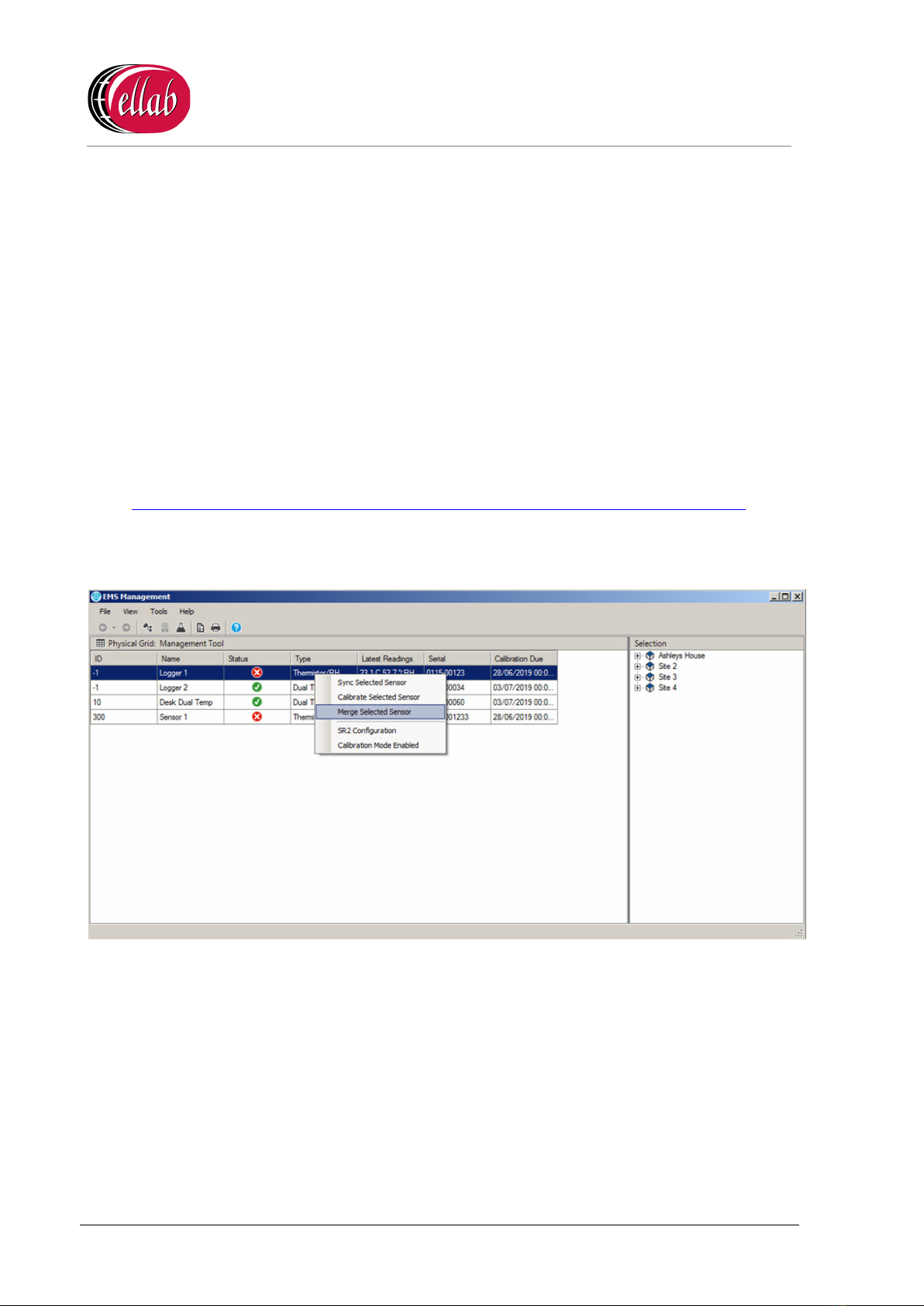
1. In EMS Remote Management Tools, right click on the Sensor (CO2or Temperature)
which is to have its collected data merged with the EMS database
For additional information on the EMS Remote Management Tools, refer to the following
sections in the EMS Online User Guide:
http://www.help.emsprocloud.com/index.html?EMS-remote-management-tool.html
2. From the displayed drop-down menu, select Merge Selected Sensor. See Figure 13
below:
Figure 13
•The Hanwell 4000 series logger download window is displayed. See Figure 14
below:

IM5984
RL4512 CO
2and Temperature Sensor Unit
Instruction Manual
Doc No. IM5984 - 3 Page 15 of 20 ellab
.com
Figure 14
3. Click on the Download button.
•The Save Data button becomes active and ‘Download complete’ is displayed in
the bottom left-hand corner of the window when the Download is complete. See
Figure 15 below:
Figure 15
4. Click on the Save Data button.
5. The Waiting for Task window is displayed, with a bar illustrating the progress of the
Merge operation. See Figure 16 overleaf:

IM5984
RL4512 CO2and Temperature Sensor
Unit
Instruction Manual
ellab.com Page 16 of 20 Doc No. IM5984 - 3
Figure 16
•When the Waiting for Task window disappears with no error messages displayed,
the data from the Unit’s memory has been successfully merged with the EMS
Database.
The Merge Collected Data process is now complete and the Data filing complete Information
window is displayed. See Figure 17 below:
Figure 17

IM5984
RL4512 CO
2and Temperature Sensor Unit
Instruction Manual
Doc No. IM5984 - 3 Page 17 of 20 ellab
.com
Appendix A
Entering a Sensor/Probe’s Calibration Settings into
EMS versions prior to 1.0.9
Note: For details on entering Calibration Settings into EMS Version 1.0.9 and later, please
refer to Section 3.1.
1. In the left-hand menu of the Editing and Configuration (View Data > Edit Mode)
window, navigate to the icon representing the RL4512 Unit, as outlined in the Accessing
Sensor Properties section of the EMS Online User Guide:
http://www.help.emsprocloud.com/index.html?accessing-sensor-properties.html
2. Click on the + sign next to the RL4512’s icon to access the Properties icon.
3. Click on the + sign next to the Properties icon in the left-hand menu to display the
Calibration icon.
4. Click on the + sign next to the Calibration icon to expand the Calibration property
entries. See Figure 18 below:
Figure 18
IM5984
RL4512 CO2and Temperature Sensor
Unit
Instruction Manual
ellab.com Page 18 of 20 Doc No. IM5984 - 3
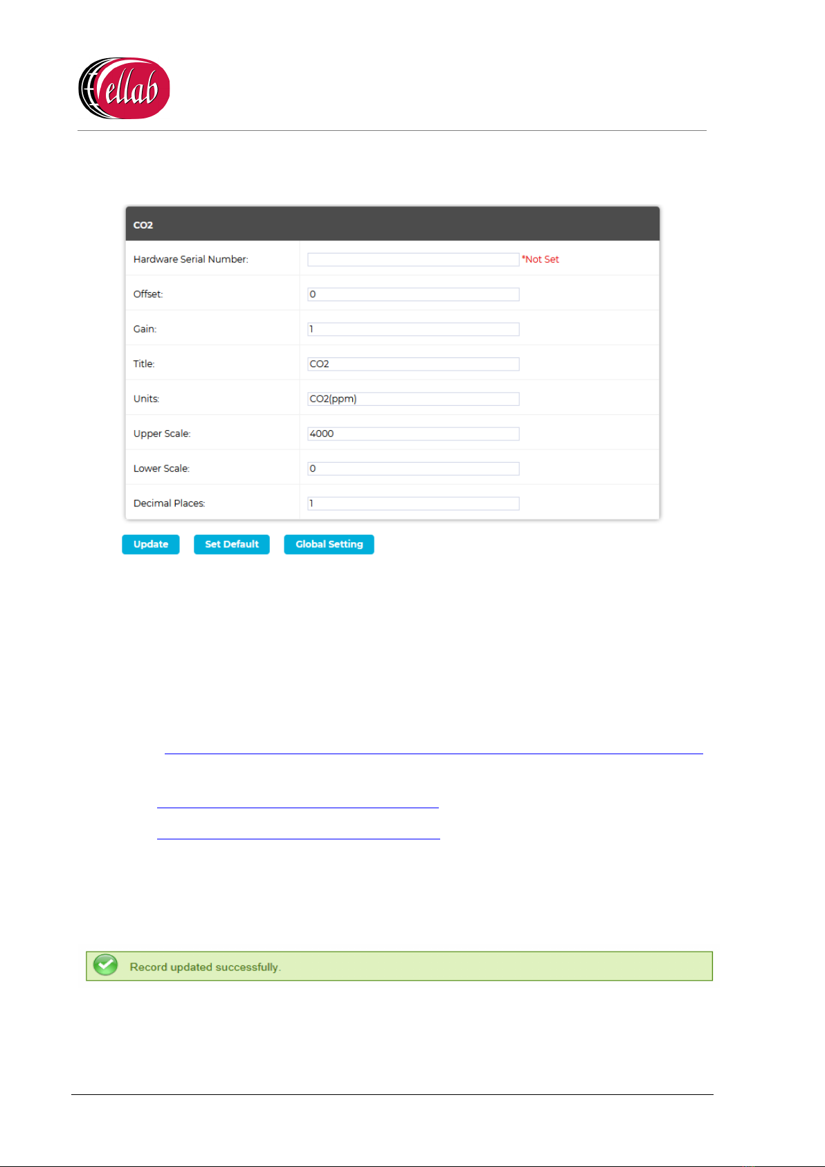
5. Click on the CO2 icon (see Figure 18 above)to display the CO2 window for the selected
RL4512 Sensor/Transmitter. See Figure 19 below:
Figure 19
6. In the displayed CO2 window, enter the Offset and Gain values for the supplied Vaisala
CO2sensor/probe into their respective fields.
•These values are listed in the CH 1 column of the table at the top of the Box Insert.
Note: Should you wish to carry out your own calibration of the Vaisala CO2
sensor/probe, please refer to both the EMS Online User Guide:
http://www.help.emsprocloud.com/index.html?calibration-management-tools.html
and the following links which are also listed on the Box Insert:
http://pd.hanwell.com/Cal-linear-sensor.xls
http://pd.hanwell.com/Cal-linear-sensor.zip
7. Select Update to confirm the details and load the Offset and Gain values into EMS.
•If the Update has been successful, the following message will be displayed. See
Figure 20 below:
Figure 20
8. Repeat Steps 1 -7 for all required RL4512 Units.
Table of contents


