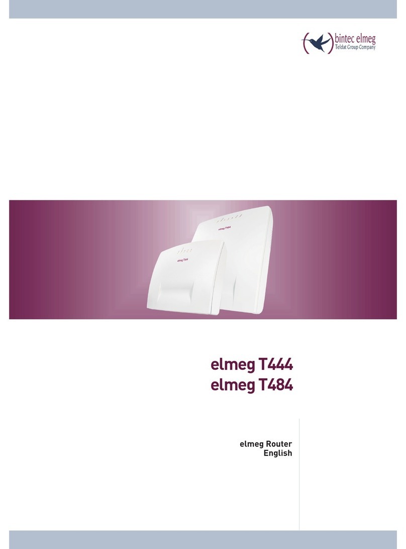
elmeg T444 User manual


Declaration of conformity and CE marks
This device meets the requirements of the following EC directive R&TTE 6/3/EG:
»Directive 1999/5/EC of the European Parliament and of the Council of 9 March 1999 on radio equip-
ment and telecommunications terminalequipmentand the mutual recognition of their conformity«.
You can also request this EC declaration of conformity at the following Internet URL: http://www.funkwerk-ec.com.
The waste container symbol with the "X" through it on the device indicates that the device must bedis-
posed of separately from normal domestic waste at an appropriate waste disposal facility at the end of
its useful service life. You will find additional information on an individual returning of the old appli-
ances under www.funkwerk-ec.com.
© 2009 Funkwerk Enterprise Communications GmbH - All rights reserved.
Reprinting of this document, even excerpts, is permitted only with the express consent of the publisher and with pre-
cise source information, regardless of the media used (mechanical or electronic).
Function descriptions included in this documentation which refer to software products of other manufacturers are
based on the software used and valid at the date the documentation was prepared or published. The product and
company names used in this documentation may be protected by trademarks.

Table of contents
Introduction. . . . . . . . . . . . . . . . . . . . . . . . . . . . . . . . . . . . . . . . . . . . . . . . 1
Router of the PABX elmeg T444 / elmeg T484 . . . . . . . . . . . . . . . . . . . . . . . . . . . . . . . . . . . . 1
What is a router? . . . . . . . . . . . . . . . . . . . . . . . . . . . . . . . . . . . . . . . . . . . . . . . . . . . . . . 1
Router of the PABX system . . . . . . . . . . . . . . . . . . . . . . . . . . . . . . . . . . . . . . . . . . . . . . . . 1
Which Internet connections are supported? . . . . . . . . . . . . . . . . . . . . . . . . . . . . . . . . . . . . . . . 1
Dial-in into the LAN (RAS). . . . . . . . . . . . . . . . . . . . . . . . . . . . . . . . . . . . . . . . . . . . . . . . 2
RAS Callback:. . . . . . . . . . . . . . . . . . . . . . . . . . . . . . . . . . . . . . . . . . . . . . . . . . . . . . . . 2
DHCP server and IP address allocation . . . . . . . . . . . . . . . . . . . . . . . . . . . . . . . . . . . . . . . . . . 3
Direct connection (DHCP) . . . . . . . . . . . . . . . . . . . . . . . . . . . . . . . . . . . . . . . . . . . . . . . . 3
Default setting of the PABX . . . . . . . . . . . . . . . . . . . . . . . . . . . . . . . . . . . . . . . . . . . . . . . 3
Default IP addressesfor thelocal area network . . . . . . . . . . . . . . . . . . . . . . . . . . . . . . . . . . . . . . 3
What are IP addresses and subnetwork masks . . . . . . . . . . . . . . . . . . . . . . . . . . . . . . . . . . . . . . 4
Example with this PABX:. . . . . . . . . . . . . . . . . . . . . . . . . . . . . . . . . . . . . . . . . . . . . . . . . . 4
Router functions . . . . . . . . . . . . . . . . . . . . . . . . . . . . . . . . . . . . . . . . . . . . . . . . . . . . . . 4
Automatic Internet access, fallback . . . . . . . . . . . . . . . . . . . . . . . . . . . . . . . . . . . . . . . . . . . . 4
Short Hold . . . . . . . . . . . . . . . . . . . . . . . . . . . . . . . . . . . . . . . . . . . . . . . . . . . . . . . . . . 4
Dynamic ISDN. . . . . . . . . . . . . . . . . . . . . . . . . . . . . . . . . . . . . . . . . . . . . . . . . . . . . . . . 4
DHCP server . . . . . . . . . . . . . . . . . . . . . . . . . . . . . . . . . . . . . . . . . . . . . . . . . . . . . . . . . 5
DNS server . . . . . . . . . . . . . . . . . . . . . . . . . . . . . . . . . . . . . . . . . . . . . . . . . . . . . . . . . . 5
DNS-Proxy . . . . . . . . . . . . . . . . . . . . . . . . . . . . . . . . . . . . . . . . . . . . . . . . . . . . . . . . . . 5
Dynamic DNS . . . . . . . . . . . . . . . . . . . . . . . . . . . . . . . . . . . . . . . . . . . . . . . . . . . . . . . . 6
Router control via system phone . . . . . . . . . . . . . . . . . . . . . . . . . . . . . . . . . . . . . . . . . . . . . 8
Statusdisplay CAPI/ TAPI in the ControlCenter . . . . . . . . . . . . . . . . . . . . . . . . . . . . . . . . . . . . . 8
Configuration examples. . . . . . . . . . . . . . . . . . . . . . . . . . . . . . . . . . . . . . . . . 9
Address assignment by DHCP -Recommended configuration - (Default setting). . . . . . . . . . . . . . . . 9
Things to note for this configuration. . . . . . . . . . . . . . . . . . . . . . . . . . . . . . . . . . . . . . . . . . . . 9
Addressassignment without DHCP (set / mixed IP addresses) . . . . . . . . . . . . . . . . . . . . . . . . . . . . 11
Things to note for this configuration. . . . . . . . . . . . . . . . . . . . . . . . . . . . . . . . . . . . . . . . . . . 12
LAN-Client (PC) Configuration . . . . . . . . . . . . . . . . . . . . . . . . . . . . . . . . . . . . . . . . . . . . . 12
PC settings in Windows operating system . . . . . . . . . . . . . . . . . . . . . . . . . . . . . . . . . . . . . . . 12
Sample configuration of a network with mixed address assignment. . . . . . . . . . . . . . . . . . . . . . . 14
Sample configuration of a network with set address assignment . . . . . . . . . . . . . . . . . . . . . . . . . . . . 15
Checking the LAN clients (PCs) . . . . . . . . . . . . . . . . . . . . . . . . . . . . . . . . . . . . . . . . . . . . 16
Configuration for Windows 98SE/ME/2000/XP . . . . . . . . . . . . . . . . . . . . . . . . . . . . . . . . . . . . 16
Checking the TCP/IP Configuration. . . . . . . . . . . . . . . . . . . . . . . . . . . . . . . . . 17
Windows 98SE / ME. . . . . . . . . . . . . . . . . . . . . . . . . . . . . . . . . . . . . . . . . . . . . . . . . . . . 17
Windows 2000 . . . . . . . . . . . . . . . . . . . . . . . . . . . . . . . . . . . . . . . . . . . . . . . . . . . . . . . 17
Windows XP . . . . . . . . . . . . . . . . . . . . . . . . . . . . . . . . . . . . . . . . . . . . . . . . . . . . . . . . 19
Configuring Internet access on a PC. . . . . . . . . . . . . . . . . . . . . . . . . . . . . . . . . . . . . . . . . . 20
InternetExplorer settings / Windows Internet options . . . . . . . . . . . . . . . . . . . . . . . . . . . . . . . . . 20
Configure firewall filters. . . . . . . . . . . . . . . . . . . . . . . . . . . . . . . . . . . . . . . . 22
Basic information about firewall configuration . . . . . . . . . . . . . . . . . . . . . . . . . . . . . . . . . . . . 22
Four place holders are provided to achieve an abstraction when defining the filters: . . . . . . . . . . . . . . . . . 23
You can configure the following parameters: . . . . . . . . . . . . . . . . . . . . . . . . . . . . . . . . . . . . . . 23
Filter Wizard . . . . . . . . . . . . . . . . . . . . . . . . . . . . . . . . . . . . . . . . . . . . . . . . . . . . . . . 25
Gaming - Filter . . . . . . . . . . . . . . . . . . . . . . . . . . . . . . . . . . . . . . . . . . . . . . . . . . . . . . . 27
1

Realplayer - Filter . . . . . . . . . . . . . . . . . . . . . . . . . . . . . . . . . . . . . . . . . . . . . . . . . . . . . 28
Mediaplayer - Filter . . . . . . . . . . . . . . . . . . . . . . . . . . . . . . . . . . . . . . . . . . . . . . . . . . . . 28
Filter update. . . . . . . . . . . . . . . . . . . . . . . . . . . . . . . . . . . . . . . . . . . . . . . . . . . . . . . . 28
2

Introduction
Router of the PABX elmeg T444 / elmeg T484
The PABX elmeg T444 / elmeg T484 is equipped with an integrated router. You can provide access to the Internetand
network several PC via this router.
What is a router?
A router allows LAN clients (computers, PC within a network) of one network (LAN) to obtain access to a different
network, for example Internet. Access to the Internet is made available by various Internet serviceproviders (ISP).
In this process, the router searches for a path on which data can be exchanged between the LAN clients in the local
network and the Internet. Linking to the Internet can be carried out via an xDSL and / or an ISDN connection.
Router of the PABX system
The PABX system router is equipped with a WAN/xDSL and a LAN port). The PABX system is connected to another
network, for example the Internet, via the WAN/xDSL port. You can hook up a DSL or cable model for connection to
the Internet.
The LAN ports are for your local network. Here, you can directly connect up to two PCs equipped with built-in net-
work cards. If you wish to network more than two PCs you can do this using an additional HUB / Switch, HomePN
(optional module, not included in standard supply scope of system), or a USB port.
LAN1 sets itself automatically (from 10 Mbit/s half-duplex up to 100 Mbit/s full duplex) to the maximum data trans-
fer rate of the remote location (PC).
These PCs are also part of your local network and can, for example, exchange files or take advantage of the Internet
connections via the router. All LAN clients that are linked are integrated into the local network via the TCP/IP proto-
col.
Further PCs can be linked to your network via RAS- access. Here, the IP address is always assigned by the telephone
system, even when the DHCP server is de-activated. Under “Address assignment” in the configuration program you
can de-activate the DHCP server and input the starting address for RAS. The following 11 IP addresses are then auto-
matically reserved for RAS.
Using the Remote Access Server (RAS) a field representative, for example, can call into the local network from an ex-
ternal location and then via the local network access the Internet. Access from anexternal location is only possible via
an ISDN connection. External access is provided with user-name and password protection. If the call is made from an
external location only, the phone number can also be monitored as anadded protection feature. Note that this access
portal is not protected by a firewall!
Note
Please note the further instructions given in the operator’s manual of the PABX system for connecting a pcs.
Which Internet connections are supported?
You can set up a connection to the Internet with your PABX system as follows:
·Dial-up connections via ISDN (using PPP protocol, with one or two ISDN B channels, i.e. at 64 kbit/s or 128
kbit/s).
These types of connections require access data with the number to be dialed, the user name and password
and, in some cases, other information such as the IP address of the name server and any information about
the data compression method that is used (VJH).
·Using xDSL (for example ADSL - T-DSL) in conjunction with a DSL modem that is compatible with your
ISP via PPPoE.
These connections require your user name and password as access data.
Router of the PABX elmeg T444 / elmeg T484 Introduction
1

·Using xDSL (for example: SDSL) in conjunctionwith a DSL modem that is compatible with your ISP with a
set, public IP address. These connections require the public IP address that you have been assigned, the IP
address of the next gateway (next hop) and the IP address for the name server of your provider.
·Tunneling. Here, data packets of one protocol are packed into the shell of a different protocol to route them
on to the Internet. At the recipient the shell is then removed and the data packet routed on with the original
protocol. This tunneling is used to overcome incompatible networks, or when taking into consideration se-
curity and cost aspects (for example PPTP). Normally, you only need your user name and password as ac-
cess data. Indicate all the data that is also specified to you by your provider (for example, number, IP
address and DNS server.
The ISP that you wish to use for your Internet connections is set in the configuration of the PABX system. You can
configure up to 10 ISPs. You can then define further settings for each ISP, such as user name, password, phone num-
ber, etc.. You can also define whether the connection to the Internet is to be set up automatically(default setting) and
that the next ISP in your list is to be selected once the connection has been established (fall-back).
When the PABX system router receives the command to establish an Internet connection this connection is set up
using the first ISP in your list. If the connection is set up successfully all of the clients in your network can access the
Internet. If the Internet connection is no longer needed (inactivity) it is terminated after a defined time.
If an Internet connection can notbe set up using the selected ISP an attempt is made to establish the connection using
the next ISP in your list (fall-back).
When an Internet connection is terminated, the first ISP in the list is used when the next connection attempt is initi-
ally carried out.
Note
For more information about configuring ISPs and establishing an internet connection, refer to the operator’s ma-
nual of your PABX.
Note
If “hubs” are installed in your network, for example, or if a connection to the Internet still exists, data packets may
continue to be sent to the router and the connection can not be terminated.
Dial-in into the LAN (RAS)
Using the Remote Access Server (RAS) a field representative, for example, can call into the local network from an ex-
ternal location and then via the local network access the Internet.Access from an external location is also possible via
an ISDN connection.
External access is provided with user-name and password protection. If the call is made from an external location
only, the phone number can also be monitored as an added protection feature. Access can be enabled for up to 8
users. A Windows enable (access to computer, files or printers) and Internet enable can also be configured for each
user.
A PC that dials into the local network via RAS is automatically assigned an IP address by the integrated DHCP server.
RAS Callback:
If you do not want to be charged for connections within your company network you can configure the RAS connecti-
on as an automatic call-back. For this, a brief connection is set up to the company network (for which you are char-
ged) that then initiates a call-back. The PABX system at your company then calls you back and you are not charged
for the ensuing connection time. You can enter a number for the corresponding RAS connection in the configurati-
on. Automatic call-back is then only possible from this number. If you do not enter a number here, the automatic
call-back can be made from any number.
Introduction Dial-in into the LAN (RAS)
2

DHCP server and IP address allocation
PCs can be provided with a major portion of the configuration required for LAN and Internet access via the DHCP
(Dynamic Host Configuration Protocol). The DHCP server integrated into the PABX is capable of supplying corre-
sponding configurations to up to 100 PCs (clients). IP addresses are dynamically allocated to the clients. The DHCP
server task of the PABX system is activated in the initial status of the PABX.
You can configure the integrated DHCP server under »Network address allocation«.
You can configure the first IP address assigned by the DHCP server. The required number of IP addresses is assigned
to the PCs (DHCP clients) in ascending order.
Eleven additional IP addresses for the DHCP server are always reserved for PCs that are integrated through RAS (re-
mote access server) into the local network. If the integrated DHCP server is activated the 11 IPaddresses which come
after the configured DHCP address range are used for RAS clients.
When the DHCP servers are de-activated the 11 IP addresses that come after the set DHCP start address will be used
for RAS clients.
Direct connection (DHCP)
This setting is used to utilize a direct WAN connection with automatic allocation of the IP addresses via DHCP. In
this case the IP address is not assigned by your PABXsystem router, but by the network in which the router is integra-
ted. The router DHCP must be de-activated in the configuration for this.
Default setting of the PABX
Default IP addresses for the local area network
In its basic setting you can use your PABX system as a router for Internet access for your local network. You have to
define (when configuring the PABX) the Internet service provider that you wish to use.
The IP addresses for your local area network are then distributed as follows:
192.168.1.1 to
192.168.1.49 Freely assignable IP addresses as for example for LAN clients with a fixed IP address
192. 168. 1. 50 to
192.168.1.69 IP addresses that are allocated to corresponding LAN clients by the PABX system.
(Number of DHCP clients: 20)
192.168.1.70 to
192.168.1.80 Reserved IP-addresses (11) RAS. These addresses must always remain reserved and
may not be assigned as set IP addresses.
192. 168. 1. 81 to
192.168.1.249 Freely assignable IP addresses as for example for LAN clients with a fixed IP address
192.168.1.250 IP address for the PABX
192.168.1.251
to
192.168.1.254
Freely assignable IP addresses as for example for LAN clients with a fixed IP address
Note
Please note that each IP address can only be assigned once. The first and last IP address for a network may not be as-
signed to LAN clients. In this example: 192.168.1.0 and 192.168.1.255.
Example for the hint:
255.255.255.0 Subnet mask for all components on the network (PABX, LAN clients,.. . )
192.168.1.250 IP address for the gateway (PABX)
192.168.1.250
Direct connection (DHCP) Introduction
3

IP address for the DNS server (PABX). The PABX system also acts as a DNS proxy in
place of the ISP DNS server.
What are IP addresses and subnetwork masks
With the initial settings IP addresses and subnetwork masks are already set for the PABX system router. Both of these
values are each 4 bytes in length.
IPaddress: 192.168.1.250
Subnetmask: 255.255.255.0
The IP address is an address that is reserved for private local networks.
The subnetwork defines that this is a Class C network in which up to 254 LAN clients can be linked. Using the subnet-
work mask an IP address can be divided into the network address and the host address (address of the PC).
Example with this PABX:
IP address of the
PABX: 192.168.1.250
IP netmask for the
PABX: 255.255.255.0
Network part of the
IPaddresses: 192.168.1.xxx
Host part of the address: x.x.x.250
Firstusable
IPaddress: 192.168.1.1 (netmask: 255.255.255.0)
Lastusable
IPaddress: 192. 168. 1. 254 (netmask: 255.255.255.0)
You can assign the available IP addresses to the individual LANclients manually, or have them assigned by the PABX
system via DHCP. No IP address may be used simultaneously by more than one client however. With regard to the
example given above this means that the address 192.168.1.250 may not be allocated again, as it is already being used
by the PABX system.
The network part of the IP address may not be changed, as otherwise the LAN clients would not all be located within
the same IP network. A PC with the IP address 192.168.2. 1 is located in a different network. A PC from the PABX net
would not be able to locate this other PC if it is not within its own network.
In addition, the same subnetwork mask must also be entered at all LAN clients located within the same network.
Router functions
Automatic Internet access, fallback
Several ISPs (ISP – Internet Service Provider) can be set up in the PABX. Connectivity to the Internet is provided via
the WAN port (e.g. DSL port), or via an ISDN port. If required, connection to theInternet can be set up automatically.
If your selected ISP is not available, the next ISP in the list will be selected automatically.
Short Hold
Short Hold means that the PABX system terminates the Internet connection automatically after a configurable time
period when there is no exchange of data from/to the Internet (inactivity). You can set this time separately for each
ISP that you have configured.
This can result in increased connection costs with frequent, short excursions into the Internet, for example for pi-
cking up e-mails, as the connection is always maintained for the duration of the set holding time.
Dynamic ISDN
Higher data transfer rates can also be achieved for Internet access via the ISDN connection by bundling the two B
channels for the connection. If an Internet connection with channel bundling is active and a B channel is needed for
telephony or fax messages, one B channel is disconnected from the Internet connection. On completion of the voice
Introduction Router functions
4

connection the B channel reverts automatically to usefor the Internet connection. This function is available for inco-
ming and outgoing voice links.
This performance feature requires that the ISDN Speed Manager be installed, or that Internet access is made via the
router! The Speed Manager is included in the T-Online installation.
Completion of call to busy subscriber:
You can not be reached by an external telephone call when you are surfing the Internet and are using two B channels
for downloading. As signaling of a further call is made via the D channel, your telephone system has the capability of
specifically de-activating one B channel (depending on current settings) so that you can take a call. You can define the
following settings in the PC Configurator.
Rejecting a call:
The caller will hear the busy signal and both B channels remain active.
Internal MSN extension number:
One B channel is de-activated (the call briefly hears music on hold, see also Page ) and the call is signaled at the sub-
scriber entered under »Internal number«. This terminal device may not be located on the same ISDN bus or at the
same USB port as the PC.
Forwarding (Call Deflection) to an external extension number :
One B channel is de-activated and the call signaled at the subscriber entered under »External number«. You can also
have the call forwarded to an external subscriber by the exchange, allowing both B channels to remain active. Calls
can also be transferred (for example for T-NetBox or cell phone) without a B channel of the telephone system being
allocated.
Normal call distribution:
One B channel is de-activated and the call signaled at the subscriber entered under »Call allocation« for the »External
number«.
Dynamic ISDN for all outgoing calls
You can not make an outside call if you are surfing in the Internet while using two B channels for downloading. Ho-
wever, depending on the PC configuration, your telephone system does have the capability to specifically de-activate
one B channel so that you can make calls while connected to the Internet.
DHCP server
PCs can be provided with a major portion of the configuration required for LAN and Internet access via the DHCP
(Dynamic Host Configuration Protocol). The DHCP server integrated into the PABX is capable of supplying corre-
sponding configurations to several PCs (LAN-clients). IP addresses are dynamically allocated to the clients. This
mode is recommended to dispense with the complicated, manual configuration of the IP addresses for the PC that
would otherwise be required.
DNS server
The DNS server (Domain Name Server) has the task of establishing names within a network. In this process the IP ad-
dresses of the PCs (e.g. LAN clients) are transformed into names. You must therefore know the name, and not the IP
address, of a PC that you wish to access, or are searching for. The DNS server can also establish names that are not in-
cluded in the local network.
DNS-Proxy
A proxy assumes a surrogate function for the local network (LAN) in a different / external network. Here, the DNS
proxy accepts the name queries from the LAN client and submits them to the external network, e.g. Internet, as its
Router functions Introduction
5

own queries. The proxy then takes the response from the external network andforwards it to the LAN client that pla-
ced the original query. In addition, the result from the query is stored for a defined time (configurable) to answer any
subsequent queries of the same type.
Dynamic DNS
Using Dynamic DNS you can also offer your own Internet services (e.g. WEB, FTP or e-mail servers). Usually you
must have a fixed line or a set IP address for this so that you can always be reached at the same URL (For example:
www.Funkwerk-ec.com).
You are assigned a new IP address by the ISP each time you dial in to the Internet however. Using Dynamic DNS you
can link this automatic (dynamic) IP address with a set name. The router will then inform your Dynamic DNS service
provider (e.g. www.dyndns.org) automatically of the new IP address. Internet enquiries for your Web services are
then automatically forwarded to your dynamic IP address via your service provider.
Using Dynamic DNS
·Configure an Internet address (URL) at a Dynamic DNS service provider. For example, at
“www.dyndns.org” configure the address “www.my-homepage.dyndns.org”.
·Configure the LAN client of the network in which you wish to offer your Web services with a set IP address.
For example, let’s say we want to configure a Web server with the IP address 192.168.1.200.
·Activate the Dynamic DNS function in the router and enter the Internet address (URL) for your Dynamic
DNS provider (in the example here www.dyndns.org).
Add the necessary filters in the firewall to allow the PC with the Web services to be reached from an external
location.
- Configure port mapping for Port 80 (HTTP protocol) to IP address 192.168.1.200.
- Configure the filters that permit incoming and outgoing WAN connections at Port 80.
·The router will automatically inform your Dynamic DNS provider of your current dynamic IP address each
time a connection is set up with the Internet. The information about the IP address is transferred after set-
ting up a new Internet connection, as well as during an ongoing Internet connection.
·A PC in the Internet enters the address (URL)“www.my-homepage.dyndns.org”. In this way it reaches
your Dynamic DNS service provider. Your service provider reroutes the connection to your current
dynamic IP address.
·Any incoming connection is handled in accordance with the configured filters. In the example given here
the incoming WAN connection at port 80 is forwarded to the LAN client with the IP address 192.168.1.200.
The available Internet sites of your Web server are displayed on the external PC.
NAT
NAT (Network Adress Translation) protects the connected LAN-clients against attacks from the Internet. Here, the
internal IP addresses are not passed on to the Internet. The router carries out the transfer to the Internet and distribu-
tes the incoming data packets in the internal system. This only requires one external IP address. The internal IP ad-
dresses are protected from attacks from outside. The internal IP addresses can not be targeted by hackers, as these IP
addresses are non-accessible.
Packet Filter Firewall
The integrated filter firewall packet also provides you with enhanced security against attacks from the Internet. A fi-
rewall acts as a logical wall for data packets between the Internet and the LAN which has »holes« for certain packets
(firewall rules, also known as filters), allowing these packets to pass through the wall. The filters are described by ru-
les whose configuration requires expert knowledge about the TCP/IP protocol family. The firewall of your PABX sys-
tem can be easily configured using a Filter Wizard in which you need to indicate (in plain text) whether you wish to
allow defined applications access to the Internet.
Introduction Router functions
6

Portmapping
You wish to access your PC from an external location via Internet. Normally, access via the firewall should be prohi-
bited. When you use port mapping, access to a router port that you have enabled is permitted from an external locati-
on. The router then forwards the access request to the defined port of the PC in the network. A fixed IP-address must
be assigned to this PC. When the PC returns data packets the IP address and port number of the PC are replaced by
the router with the number for the port mapping port and the router IP. For “outsiders” on the Internet it then appe-
ars as though there is only one connection to the router.
Note
Please note that when you use port mapping the firewall for the ports enabled for this function is ineffective. The
target PC in your LAN may then be susceptible to any potential attacks.
Port mapping is practical when you wish to run a game server on your own, for example.
·You can make this server accessible via the Internet to other users.
·Or, if you require certain peer-to-peer file sharing software that provides greater download bandwidth.
·When the corresponding PC in your LAN is to be accessible from the Internet (not possible in the standard
configuration with NAT). In this case, certain UDP and TCP ports must be rerouted to a PC in the LAN.
RAS-Server
Using the Remote Access Server (RAS) a field representative, for example, can call into the local network from an ex-
ternal location and then via the local network access the Internet.Access from an external location is also possible via
an ISDN connection.
External access is provided with user-name and password protection. If the call is made from an external location
only, the phone number can also be monitored as an added protection feature. Access can be enabled for several
users. A Windows enable (access to computer, files or printers) and Internet enable can also be configured for each
user.
Note
Note that this access portal is not protected by a firewall!
A PC that dials into the local network via RAS is automatically assigned an IP address by the integrated DHCP server.
Time-controlled router inhibition
With the aid of the calendar, or a manual function of the PABX system, you can set the time(s) of day when Internet
access is possible (permitted). These times are defined via the calendar assigned to the router in the configuration.
Here, it is stipulated that Internet connections can not be set up during night-time operation. You should therefore
set the switching times accordingly. Starting with Version 4 of system phones CS290/CS410, the telephones can be
switched using function keys on the phone; this setting is then retained until the next calendar-based switchover.
LAN-CAPI
The package includes a program called »CAPI for LANs« for use in your network. This software can be installed on
any PC in the network. This gives you the possibility of running your CAPI application from a central location via an
interface, i. e. the PABX system. There is no ISDN card required for the PCs. Please note that software used for the
CAPI application may require certain license agreements with the software manufacturer. The program »CAPI in
LAN« does not require a license to run.
Router functions Introduction
7

LAN-TAPI
The package includes a program called »TAPI for LANs« for use in your network. This software can be installed on
any PC in the network. This gives you the possibility of running your TAPI application from a central location via an
interface, i. e. the PABX system. There is no ISDN card required for the PCs. Please note that software used for the
TAPI application may require certain license agreements with the software manufacturer. The program »TAPI in
LAN« does not require a license to run.
Blocking of Internet access by the provider
After several failed attempts of inputting user names or passwords the provider will block access to the Internet for a
defined period. To prevent this the router only allows three attempts to be made. After that you must then reconfigu-
re the router and enter a correct user name and password. The router must then be enabled again after this via the
Control Center.
Connection test
You can test the connection to your provider without a connection actually being set up. The item »Connection test
T-Online for DSL and ISDN« is given in the provider list in the configuration. Select this item as the first provider and
store it in the PABX system. You can then manually set up a connection to the Internet via the ControlCenter and the
results for this connection are then displayed after a few seconds. No actual Internet connection is established here
however. If the results are positive delete the current provider and enter the settings supplied by your provider in the
configuration for setting up Internet connections.
Router control via system phone
Starting with Version 4 you can configure a function key on system telephones CS290 / CS410 /CS400xt for control-
ling the router.
LED Settings
Through PABX system configuration you can de-activate the LEDs, except for the »On« LED. When you re-activate
the LEDs the »ISDN« LED may indicate a false status. You should therefore disconnect the external ISDN port for a
brief period from the NT.
Status display CAPI / TAPI in the ControlCenter
Information used for monitoring the CAPI-TAPI functions can be displayed usingthe Control Center menu. Indica-
tion of the associated function(s) is made only when TAPI and CAPI clients are installed on your PC.
·The number of TAPI licenses currently in use (max. 10) is indicated when there is a TAPI connection with
the PABX system.
·The number of CAPI licenses (max. 10) is indicated, along with allocation of the internal and external B
channels (max. 2 each), when there is a CAPI connection with the PABX system.
Introduction Router functions
8

Configuration examples
Address assignment by DHCP -Recommended configuration - (Default setting)
Address assignment via DHCP is the easiest configuration method for the PABX system and at the clients (PCs).
You can configure a LAN client in the network such that it automatically receives its IP address from a DHCP server
from the PABX system on startup. In this case, youdo not have to enter an IP address or subnetwork mask in the con-
figuration of the LAN client.
Things to note for this configuration.
PABX:
In its initial setting the PABX system is pre-configured for address assignment via DHCP.
You need to choose an ISP. To do this follow the instructions given in the manual, or the brochure »On the fast track
to the Internet«.
Note
When delivered, the DHCP server is already activated and pre-configured. If required you can define the start ad-
dress (first IP address allocated by DHCP) and the maximum number of LAN clients (PCs).
LAN-Client (PC) Configuration:
PCs with operating systems starting from Windows 98SE are already correctly configured in their standard settings
for address assignment via DHCP.
If other means of Internet connection, for example modem or an ISDN card, have already been configured on the
LAN client (PC) observe the information given in the section»Settings in Internet Explorer / Internet Options with
Windows« in this manual.
Note
Please keep in mind that any changes made to the Windows network settings may have serious effects on the LAN
clients (PCs). Other methods of connection or applications may also be affected by these changes. In the event that
your network settings have already been changed contact your system administrator. You may have to backup all of
your data. The configuration presented in the following represents only one of many possibilities. These settings
are recommended. However, depending on the infrastructure of your environment, it may be meaningful to choose
a different configuration.
If you need to reset the Windows network settings to their standard (default) status proceed as follows:
Example Windows 98SE /ME:
·Open the Control Panel from the Windows Start Menu.
·Windows 98SE: Open the folder »Network«.
·Windows ME: Right-click on »LAN connection« and then click on »Properties«.
·Select »TCP/IP« and click »Properties«.
Address assignment by DHCP -Recommended configuration - (Default setting) Configuration examples
9

Note
The network adapter connected to the PABX system must be linked to the TCP/IP protocol, which is a component
of Windows. You may have to manually add this protocol. The network adapter may only be linked to the T-DSL /
PPP0E protocol, especially if a stand-alone version of the T-DSL driver has been installed. Add the TCP/IP protocol
manually using the buttons »Add«, »Protocol«, »Microsoft«, »TCP/IP«.
·Then specify that the PC is to receive its IP address automatically. All other settings, for example DHCP,
network mask, gateway and DNS server should be de-activated or blank. The PABX system automatically
transfers all required settings to the client (PC) via DHCP.
·Confirm your settings by clicking OK.
Example Windows 2000 and Windows XP:
·Open the Control Panel from the Windows Start Menu.
·Under Windows 2000 open the folder »Network and Dial-up Connections«.
·Under Windows XP open the folder »Network connections«.
·Select the »LAN Connection« for the PABX by pressing the right mouse button. Then click »Properties«.
·Select »TCP/IP« and click »Properties«.
·Then specify that the PC is to receive its IP address automatically. All other settings, for example DHCP,
network mask, gateway and DNS server should be de-activated or blank. The PABX system automatically
transfers all required settings to the client (PC) via DHCP.
·Confirm your settings by clicking OK.
Note
Also follow the instructions given in the documentation and the Help function of your operating system. If it is not
possible to set up a connection to the PABX, or to the Internet, refer to the section »Checking the LAN client (PC)
configuration« in this manual.
Configuration examples Address assignment by DHCP -Recommended configuration - (Default setting)
10

Sample configuration of a network with DHCP address allocation
Configuration of the PABX system in its initial settings
1NT
2NT / Splitter
3Connection for the service provider
4Modem
5Network PC 2 at HUB / Switch
6PC 1 at USB port
IPaddress for thePABX: 192.168.1.250
Subnetmask: 255.255.255.0
Startaddress DHCP: 192.168.1.50
Number of DHCP addresses:20
PC1
IPvia DHCP: 192.168.1.50 transmitted automatically via DHCP.
Gateway: transmitted automatically via DHCP.
DNS server: transmitted automatically via DHCP.
Subnetmask: transmitted automatically via DHCP.
PC2
IPvia DHCP: 192.168.1.53 transmitted automatically via DHCP.
Gateway: transmitted automatically via DHCP.
DNS server: transmitted automatically via DHCP.
Subnetmask: transmitted automatically via DHCP.
In the example given here, the IP addressesfor the clients (PCs) can lie within a range from IP 192. 168. 1. 50 to 192.
168. 1. 69. The IP addresses are assignedin the order that the clients (PCs)request them (for example by switchingon
the PCs). If an IPaddress is released (forexample by switching off a PC)that IP address isthen available to be
re-assignedagain.
Address assignment without DHCP (set / mixed IP addresses)
You can dispense with a DHCP server in a network or also configure LAN clients (PCs) with set IP addresses as an ad-
dition to the DHCP clients.
Note
Much more time and effort is involved for configuring the network if a configuration is chosen without DHCP. If
Address assignment by DHCP -Recommended configuration - (Default setting) Configuration examples
11
a/b1
a/b2
a/b3
a/b4
a/b5
a/b6
a/b7
a/b8
1 2
NO
1 2
NO
S0 internS0extern
a/b1
2a/b
1a/b 3a/b
4a/b
Modul S0 intern
2a/b
1a/b 3a/b
4a/b
5a/b
6a/b
a2a1 b1 b2
Power
ISDN / POTS
DSL
LAN
USB
Modem
12
3
4
5
6

you are relatively new to Windows network configuration, we recommend a configuration using DHCP.
Things to note for this configuration.
PABX:
You can de-activate the DHCP server for the PABX system using the »Professional Configurator« program.
Note
You may have to adapt the IP addresses and subnetworks of the PABX system to the settings present on the LAN
clients (PCs). For information about this use the online Help function of the Configurator.
1NT
2NT / Splitter
3Connection for the service provider
4Modem
5External HUB / Switch by means of LAN2
(100 MBit/s)
6Network PC 4 at HUB / Switch
7Network PC3 at the HUB / Switch
8Network PC2 at the HUB / Switch
9PC 1 at USB port
LAN-Client (PC) Configuration
You must make the following minimum settings manually:
·IP address for the LAN client (PC)
·Netmask / Subnet mask (which is also entered in the PABX router)
·IP address of the PABX system as the gateway (interface to other networks, for example Internet)
·IP address of the PABX system as the DNS server (server that converts the Internet addresses into IP ad-
dresses)
Note
Observe the instructions for address assignment given on the previous pages.
PC settings in Windows operating system
The procedures described below deal only with examples which may differ somewhat depending on the operating
system used and the configuration of the PC.
Configuration examples Address assignment by DHCP -Recommended configuration - (Default setting)
12
a/b1
a/b2
a/b3
a/b4
a/b5
a/b6
a/b7
a/b8
1 2
NO
1 2
NO
S0 internS0extern
a/b1
2a/b
1a/b 3a/b
4a/b
Modul S0 intern
2a/b
1a/b 3a/b
4a/b
5a/b
6a/b
a2a1 b1 b2
Power
ISDN / POTS
DSL
LAN
USB
Modem
12
3
4
5
6
7
8
9

Note
Please keep in mind that any changes made to the Windows network settings may have serious effects on the LAN
clients (PCs). Other methods of connection or applications may also be affected by these changes. In the event that
your network settings have already been changed contact your system administrator. You may have to backup all of
your data. The configuration presented in the following represents only one of many possibilities. These settings
are recommended. However, depending on the infrastructure of your environment, it may be meaningful to choose
a different configuration.
Example Windows 98SE and Windows ME:
·Open the Control Panel from the Windows Start Menu.
·Open the »Network« folder
·Select »TCP/IP« and click »Properties«.
·Now select whether the PC is to receive its address automatically from a DHCP server, or if it is to be assig-
ned as permanent IP address. Edit or supplement the settings for network mask, gateway and DNS server as
appropriate. Refer to the parameters that are to be set in the sample configuration with mixed address as-
signment, or in the sample configuration with set address assignment on the following pages.
·Confirm your settings by clicking OK.
Example Windows 2000 and Windows XP:
·Open the Control Panel from the Windows Start Menu.
·Under Windows 2000 open the folder »Network and Dial-up Connections«.
·Under Windows XP open the folder »Network connections«.
·Right-click on »LAN connection« and then click on »Properties«.
·Select »TCP/IP« and click »Properties«.
·Now select whether the PC is to receive its address automatically (from a DHCP server), or if it is to be assig-
ned as set (permanent) IP address. Edit or supplement the settings for network mask, gateway and DNS
server as appropriate. Refer to the parameters that are to be set in the sample configuration with mixed ad-
dress assignment, or in the sample configuration with set address assignment on the following pages.
·Confirm your settings by clicking OK.
Note
Also follow the instructions given in the documentation and the Help function of your operating system.
Note
A further option available is assigning a portion of the IP addresses manually and having the remaining addresses
allocated by DHCP. Ensure that the IP address for the router and any manually assigned IP addresses are not located
in the range for available DHCP addresses.
Address assignment by DHCP -Recommended configuration - (Default setting) Configuration examples
13

Sample configuration of a network with mixed address assignment
Set IP addresses and IP addresses allocated by DHCP
1NT
2NT / Splitter
3Connection for the service provider
4Modem
5External HUB / Switch by means of LAN2
(100 MBit/s)
6Network PC 4 at HUB / Switch
7Network PC3 at the HUB / Switch
8Network PC2 at the HUB / Switch
9PC 1 at USB port
IPaddress for thePABX: 192.168.1.250
Subnetmask: 255.255.255.0
Startaddress DHCP: 192.168.1.50
Number of DHCP addresses:20
PC1
Fixed IP: 192.168.1.91
Gateway: 192.168.1.250
DNS server: 192.168.1.250
Subnetmask: 255.255.255.0
PC2
Fixed IP: 192.168.1.93
Gateway: 192.168.1.250
DNS server: 192.168.1.250
Subnetmask: 255.255.255.0
PC3
IPvia DHCP: 192.168.1.50 transmitted automatically via DHCP.
Gateway: transmitted automatically via DHCP.
DNS server: transmitted automatically via DHCP.
Subnetmask: transmitted automatically via DHCP.
Configuration examples Sample configuration of a network with mixed address assignment
14
a/b1
a/b2
a/b3
a/b4
a/b5
a/b6
a/b7
a/b8
1 2
NO
1 2
NO
S0 intern S0 extern
a/b1
2a/b
1a/b 3a/b
4a/b
Modul S0 intern
2a/b
1a/b 3a/b
4a/b
5a/b
6a/b
a2a1 b1 b2
Power
ISDN / POTS
DSL
LAN
USB
Modem
12
3
4
5
6
7
8
9

PC4
IPvia DHCP: 192. 168. 1. 51 transmitted automatically via DHCP.
Gateway: transmitted automatically via DHCP.
DNS server: transmitted automatically via DHCP.
Subnetmask: transmitted automatically via DHCP.
Sample configuration of a network with set address assignment
IPaddress for thePABX: 192.168.1.250
Subnetmask: 255.255.255.0
Startaddress DHCP: DHCP server is off.
Numberof DHCP addresses: DHCP server is off.
PC1
Fixed IP: 192.168.1.81
Gateway: 192.168.1.250
DNS server: 192.168.1.250
Subnetmask: 255.255.255.0
PC3
Fixed IP: 192.168.1.83
Gateway: 192.168.1.250
DNS server: 192.168.1.250
Subnetmask: 255.255.255.0
PC4
Fixed IP: 192.168.1.84
Gateway: 192.168.1.250
DNS server: 192.168.1.250
Subnetmask: 255.255.255.0
PC5
Fixed IP: 192.168.1.85
Gateway: 192.168.1.250
DNS server: 192.168.1.250
Subnetmask: 255.255.255.0
Sample configuration of a network with mixed address assignment Configuration examples
15

Checking the LAN clients (PCs)
Configuration for Windows 98SE/ME/2000/XP
If a connection to the PABX system, or to the Internet can not be set up you can check the configuration of the LAN
clients (PCs) based on the following information.
Note
The procedure described here assumes that you are using the recommended configuration with address as-
signment by DHCP.
The PC is linked to the PABX system via Ethernet (LAN1 jack).
·Check to ensure that the network adapter (Ethernet adapter, Home Phoneline Networking Adapter or
USB) installed in the LAN client (PC) is connected properly to the PABX system. The connection status is
displayed by the LEDs of the PABX. A description of the LEDs is given in the operator’s manual for the
PABX system.
·Check to ensure that the PABX system has assigned an IP address to the LAN-Client (PC) (see page in secti-
on »Checking the TCP/IP Configuration«).
·Check to ensure that an Internet service provider (ISP) has been configured in your PABX (see operator’s
manual for the PABX, leaflet »On the fast track to the Internet« or the online Help function of your PABX
system).
·Check to ensure that the Internet browser(s) has(have) been configured correctly in your PC (see Page in
section »Settings im Internet Explorer / Internetoptionen of Windows«).
·If you have made the settings as described above, the telephone system will establish a connection to the In-
ternet automatically (e. g. by opening the Internet Explorer, inputting an Internet URL and confirming
with “Enter”) when requested to do so by an application (default setting).
·Check to ensure that automatic connection to the Internet has been de-activated (see Configurator Net-
work«, »Internet«); the connection must then be established manually via the elmeg ControlCenter.
The PC is linked to the PABX system via USB.
·Using the Windows 98SE/ME/2000/XP operating systems you can only run one LAN client (PC) at the USB
port of the PABX system.
·The required USB driver is installed automatically when you initially connect the PC with the PABX sys-
tem. This driver is located on the CD supplied with the system.
·After installing the USB driver successfully, follow the procedure for Ethernet LAN clients.
Note
The USB driver supplied with the system (RNDIS) is located in the device manager of the Windows control panel as
a virtual network adapter. Communication between the PABX system and the PC connected via USB is effected via
the TCP-IP protocol. Data for LAN-CAPI are also transferred using this protocol.
Configuration examples Checking the LAN clients (PCs)
16
Other manuals for T444
1
This manual suits for next models
1
Table of contents
Other elmeg Network Router manuals
