SyxthSense Ltd
Online Store: www.syxthsense.com Copyright ©2005 SyxthSense Ltd – 09/2005
Enquiries: T: 0870 20 80 100 F: 0870 20 80 200 PS SW4.10– 2/6
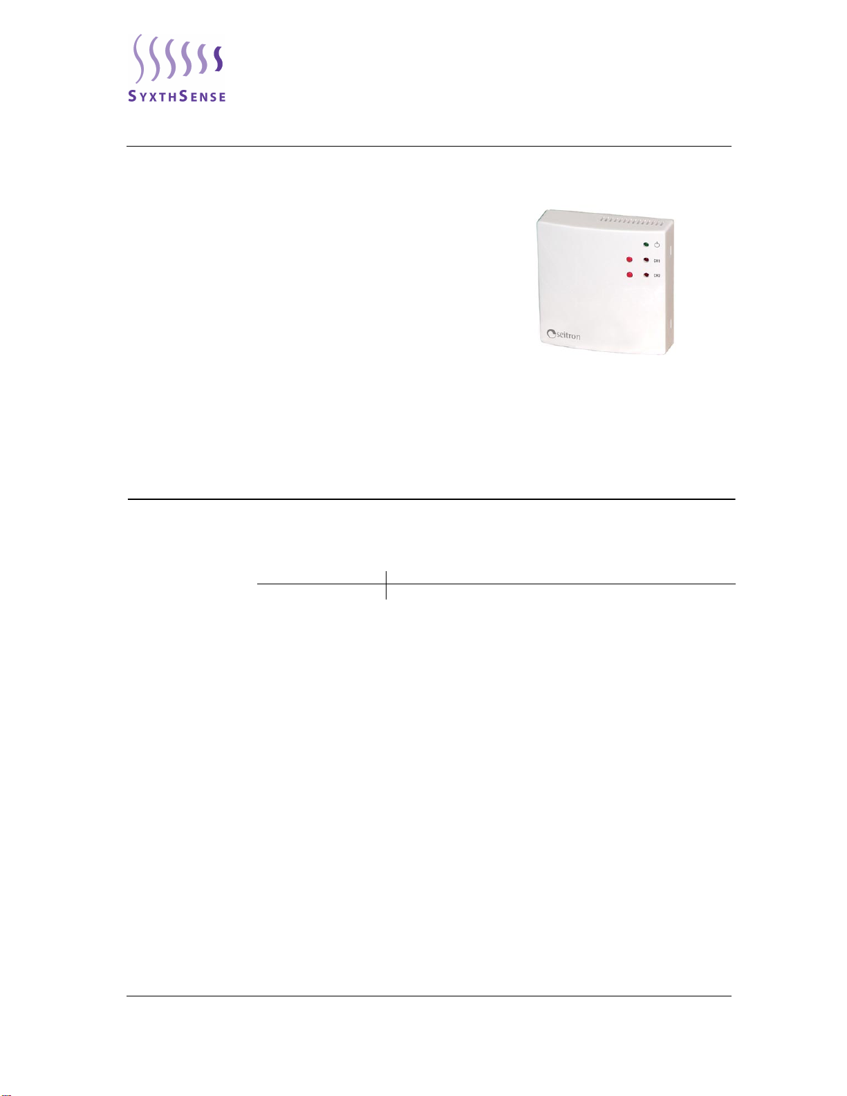
Overview The ITP F22 1 is a device capable of turning on and off at any distance one or two electric
appliances thus allowing to control systems like burners, air-conditioners, small irrigation plants
through the use of the telephone public line PSTN (Public Switched Telephone Network).
The interface answers the incoming call after a number of rings set by the user and is only activated
when the internal four digits secret code exactly matches the one composed by the user on the
telephone keyboard.
The interface also features two input channels, thus allowing a remote feedback of the state of a
certain appliance (i.e. if it is on or off) or the state of a voltage free contact of a sensor (like a door or
gate sensor, to know if they are open or closed). The device features an internal digital nonvolatile
memory so that it can ’remember’ its state even in case of a power failure and restore the correct
operating state as soon as the power returns. Two pushbuttons located on the interface front panel
can be used to change the outputs state as well as to show the input state.
In case the interface is wired on the same line as that of a fax machine, a special option can be
activated: when this is activated the interface is instructed to answer after it receives two calls with
one ring each. With this ’trick’ the interface can answer the call before the fax machine does. On the
front panel are also located two red indicators, used to show the inputs or the outputs actual state
(see further) and one green indicator, whose purpose is to show the presence of power, an incoming
call or the state of the communication established.
The device can be easily mounted on a wall with the screws and plastic shells supplied in the
package.
Operation The telephone interface ITP F22 1 answers a phone call after 2 rings (factory setting) or after a
number of rings set by the user. The interface gives for this an acoustic feedback with a short music
jingle. When the four digits secret code is composed by the user on the telephone keyboard, the
interface plays a little longer music jingle thus giving access to all the available configuration and
control commands.
All commands are described in the following parameters; in case of an error in inputing a command
sequence, the operation can be aborted by pressing *so that the sequence can be composed again.
In case for 5 consequent times the secret code is composed in a wrong way, the interface
automatically terminates the phone call.
The same happens in case for at least 30 seconds no command is issued by the user. Anyway it is
always possible to make a new call. This telephone interface can be driven also by a mobile phone
or by another device (computer or alarm system), provided it can issue the correct multi-frequency
tones (DTMF).
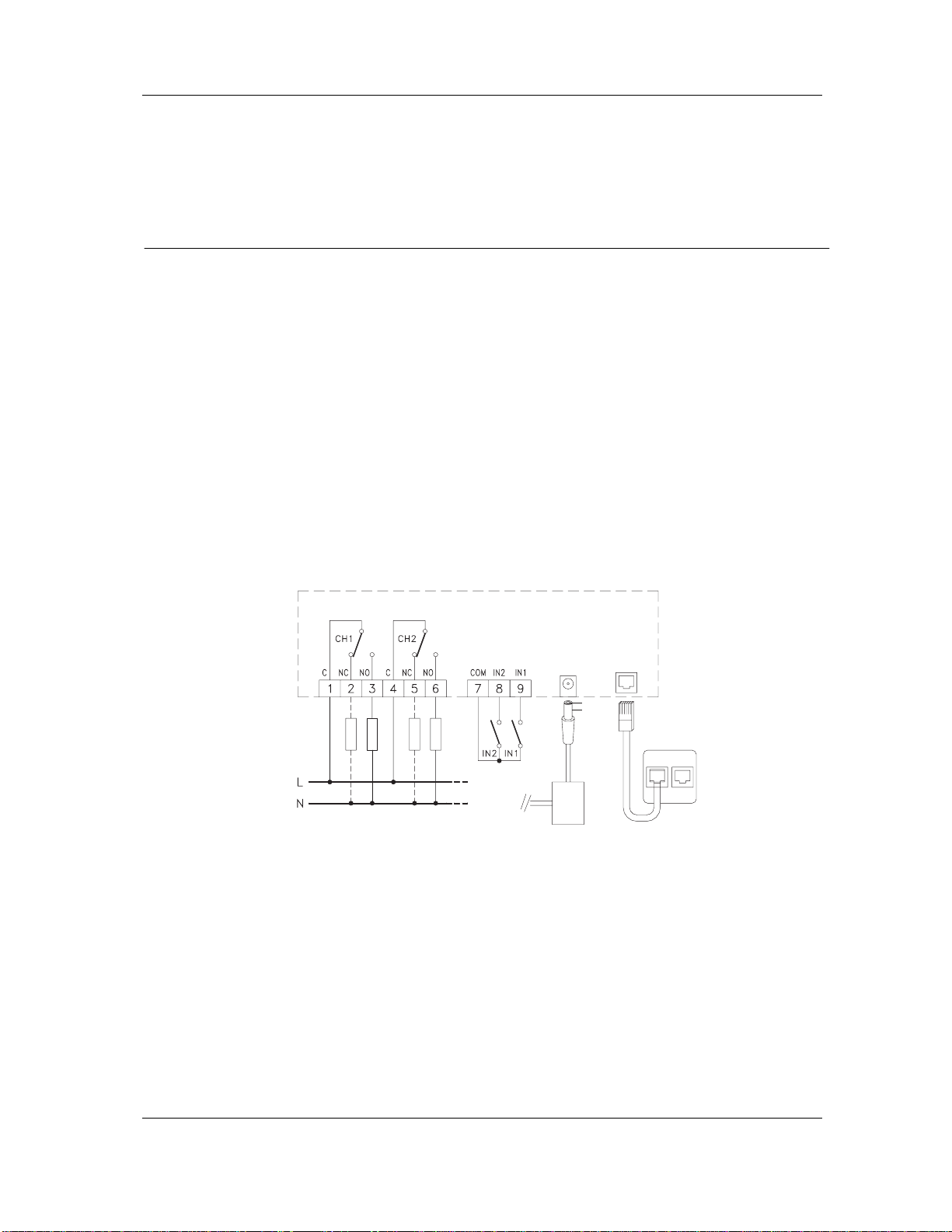
CH1 and CH2 Outputs
Control When the sequence *01 is composed on the keyboard, the CH1 output relay control mode is
initiated. The interface replies with a deep single note sound in case the relay is inactive or with a
high double note sound in case it is active. If the key 0is pressed the relay turns off meanwhile it is
turned on when a 1is pressed.
Each time the interface receives a command it also replies with the new state of the relay.
Entering the command *02 from the telephone keyboard the CH2 output relay control mode is
initiated, which is then carried out as for channel CH1.
IN1 and IN2 Inputs
Control When the sequence *11 is entered from the telephone keyboard an interrogation on the IN1 input
state is made. The interface then replies either with a deep single note sound when the input contact
is open or with a high doublenote sound when it is closed.
When the sequence *12 is entered the IN2 input state is checked with exactly the same way of
operation.
Setting the Number of
Rings at the Answer The command *7 “Number of rings” # sets the number of rings the interface waits before
answering the incoming phone call. This number can be set from 1 to 10 by simply pressing the
relevant digit on the phone keyboard, except for 10 which is set by pressing the digit.
Examples:
If *74# is composed the interface answers after 4 rings.
If *70# is composed the interface answers after 10 rings.
If the command sequence was correct the interface gives a successful feedback with a dual-tone
sound; in case of failure instead it gives a single-tone sound. In case of success the setting of
number of rings is stored in memory and maintained even in case of absence of power.
Note: The factory setting for this parameter is 2 rings.