PAC RP5-GM11 User manual

Radio Replacement & Steering Wheel Control Interface
with OnStar Retention for General Motors Vehicles
RP5-GM11
© 2018 AAMP Global. All rights reserved. PAC is a Power Brand of AAMP Global.
PAC-audio.com
P ifi A C ti
Page 1
Rev: 5
Date: 050918
Introduction and Features
Important Notes
Wiring Connection Chart
Illustration / Schematic
The RP5-GM11 interface allows the replacement of a factory radio in select General Motors vehicles with Class II radios.
Using this interface will retain factory features such as OnStar, steering wheel controls (SWC), warning chimes, Rear
6HDW&RQWUROV56&5HDU6HDW(QWHUWDLQPHQW56(DQGWKH%26(DPSOL¿HUZKHQWKHRULJLQDOUDGLRLVUHPRYHG7KH
RP5-GM11 also provides data bus driven outputs such as retained accessory power (RAP), vehicle speed signal (VSS),
illumination, reverse trigger and parking brake.
1.These instructions only apply to R.2.2.6.13 or later revisions. The revision info can be found on a small white sticker on the
interface and packaging.
2.The radio select rotary switch on the side of the interface must be adjusted to the proper radio setting before plugging the
interface into the vehicle (see next page for setting chart).
3.The interface comes pre-programmed for all of the vehicles factory SWC functions and does not require programming unless
you wish to re-assign the SWC functions to different buttons. The SWC can always be restored to default settings by pressing
DQGUHOHDVLQJWKHSURJUDPEXWWRQRQWKHVLGHRIWKHLQWHUIDFHRQFHDQGZDLWLQJVHFRQGVIRUWKH/('WRÀDVKWLPHVPLEASE
127('XHWRWKHPDQ\GLIIHUHQWSRVVLEOH2(06:&FRQ¿JXUDWLRQVVRPHDSSOLFDWLRQVPD\QHHGWREHUHSURJUDPPHG
for the SWC assignments to make sense. Whatever you assign as aftermarket volume commands will also be the
OnStar volume commands.
4.The aftermarket radio must have an auxiliary input in order for the factory RSE audio to be retained through the cabin speakers.
5.RSC buttons that are identical to the SWC will mimic the SWC one for one.
6.7KH/('ZLOOÀDVKZKHQHYHUD6:&EXWWRQLVSUHVVHG
SWC Connection
See above chart for
different radio type
connections
Wiring SWC Connection
Power and Speaker
Connections
Rear Seat Entertainment
Audio Retention Harness
Aftermarket
Radio
Connections
Vehicle
Connections
Light Green Parking Brake Output (-)
Pink Vehicle Speed Output
Blue Not Used
Blue / White Factory Amp Turn On
Input (required for Bose
systems)
Orange / White Illumination Output (+)
Purple / White Reverse Output (+)
Brown Loop Mute Loop - See
installation note 6.
Aftermarket Radio Connections
Yellow * +12v from RP5
Yellow * +12v from vehicle
Black ** Ground from RP5
Black ** Ground from vehicle
Red Acc. Output
White Front Left + input
White / Black Front Left - input
Grey Front Right + input
Grey / Black Front Right - input
Green Rear Left + input
Green / Black Rear Left - input
Purple Rear Right + input
Purple / Black Rear Right - input
SWC Connector
Blue / Yellow Kenwood, Newer JVC
3.5mm Jack
Alpine, JVC, Clarion,
Fusion, Pioneer, Sony,
Dual, Axxera, Lightning
Audio, Jensen, Rockford
Fosgate
IMPORTANT NOTES REGARDING YELLOW AND BLACK WIRE CONNECTIONS
* Connect both Yellow wires from the
RP5 harnesses to the radio’s 12v
constant input.
** Connect both Black wires from the
RP5 harnesses to the radio’s ground
input.
F====t=======1
F=====+=======1.....__
_
___j___
___
_J
F====l======J
r----+---_J
F====t======~
.....__
_
____l_
___
_J

Radio Replacement & Steering Wheel Control Interface
with OnStar Retention for General Motors Vehicles
RP5-GM11
© 2018 AAMP Global. All rights reserved. PAC is a Power Brand of AAMP Global.
PAC-audio.com
P ifi A C ti
Page 2
Rev: 5
Date: 050918
Installation Steps
1. The radio select rotary switch on the side of the interface must be adjusted to the proper radio
setting before plugging the interface into the vehicle.
2. Make all connections as described in the charton page 1. Be sure to connectboth Yellow wires (one from vehicle harness
and one from RP5 harness) and both Black wires (one from vehicle harness and one from RP5 harness) while making these
connections.
3. )DFWRU\LQVWDOOHGDPSOL¿HUVZLOOGHWHUPLQHWKHDXGLRRXWSXWFRQQHFWLRQ,IWKHYHKLFOHKDVDIDFWRU\LQVWDOOHGDPSOL¿HUXVHWKH
IDFWRU\DPSOL¿HUDXGLRORFDWLRQ,IDIDFWRU\LQVWDOOHGDPSOL¿HULVQRWSUHVHQWXVHWKHQRQDPSOL¿HGIDFWRU\DXGLRORFDWLRQ
4. Ifthe aftermarketradio is equipped with an auxiliary inputand you wish to retain the factory RSE audio, plug the RCA
connectors from the secondary harness into the radios auxiliary input.
5. With the ignition off and the driver door opened: Connectthe interface to the vehicle’s harness(es). Connecting the
interface with the ignition on can cause erratic behavior. Please make sure the ignition is off and the driver door is opened
when performing this step.
6. Plug the CMX chime module in if necessary (Ifthe vehicle chimes when the radio is removed the CMX is notnecessary).
PLEASE NOTE: In order to getthe bestpossible sound outofthe CMX, please mountit in a place free and clear ofany
REVWUXFWLRQVSUHIHUDEO\DVFORVHDVSRVVLEOHWRWKHERWWRPRIWKHGDVKSRLQWLQJGRZQWRZDUGWKHÀRRURIWKHYHKLFOH
7. The
Mute loop (if notcut) will turn the accessory outputoff when an OnStar or Bluetooth call is made or received. Ifthe
aftermarketradio has a mute input, cutthis loop and connectthe outer brown wire to the mute input.
8. Connectthe SWCwire according to the charton page 1 (aftermarketradio MUST supporta wired remote input).
9. Ifyou wish to reassign functions to the SWCfollow the programming instructions on the nextpage.
IMPORTANT! The interface comes pre-programmed for the functions listed in the chartbelow and does notrequire programming
unless you wish to re-assign the SWCfunctions to differentbuttons. The SWCcan always be restored to defaultsettings by
SUHVVLQJWKHSURJUDPEXWWRQRQWKHVLGHRIWKHLQWHUIDFHRQFHDQGZDLWLQJVHYHQVHFRQGVIRUWKH/('WRÀDVKWKUHHWLPHV
Alpine JVC Kenwood Clarion Sony / Pioneer Fusion
V
olume + Volume + Volume + Volume + Volume + Volume + Volume +
V
olume - Volume - Volume - Volume - Volume - Volume - Volume -
Source Up Source Source Disc/FM+ Source Source Source
Source Down Band Preset + Disc/AM N/P Band Off
Seek Up Track + Track + Track + Search + Track + Track +
Seek Down Track - Track - Track - Search - Track - Track -
V
oice Voice Voice Voice Voice Voice Mute
Prog Preset Up Preset - Source Band Preset + Audio
DefaultSteering Wheel Control Programming
Default SWC Button Assignments
Alpine JVC Kenwood Clarion Sony / Pioneer Fusion
Volume + 9ROXPH 9ROXPH 9ROXPH 9ROXPH 9ROXPH 9ROXPH
Volume - 9ROXPH 9ROXPH 9ROXPH 9ROXPH 9ROXPH 9ROXPH
Seek Up 7UDFN 7UDFN 7UDFN 6HDUFK 7UDFN 7UDFN
Seek Down 7UDFN 7UDFN 7UDFN 6HDUFK 7UDFN 7UDFN
Voice 9RLFH 9RLFH 9RLFH 9RLFH 9RLFH 0XWH
End 6RXUFH 6RXUFH 6RXUFH 6RXUFH 6RXUFH 6RXUFH
Default SWC Button Assignments (Corvette)
1
2
3
4
5
6
7
8
9
0
Alpine JVCKenwood /
Lightning Audio
Clarion /
Nakamichi
Pioneer /
Other* Sony Fusion
12 3 4 7 8 9
*Other - Dual / Axxera, Jensen, Rockford Fosgate
SET RADIO SELECT SWITCH
®
I----------

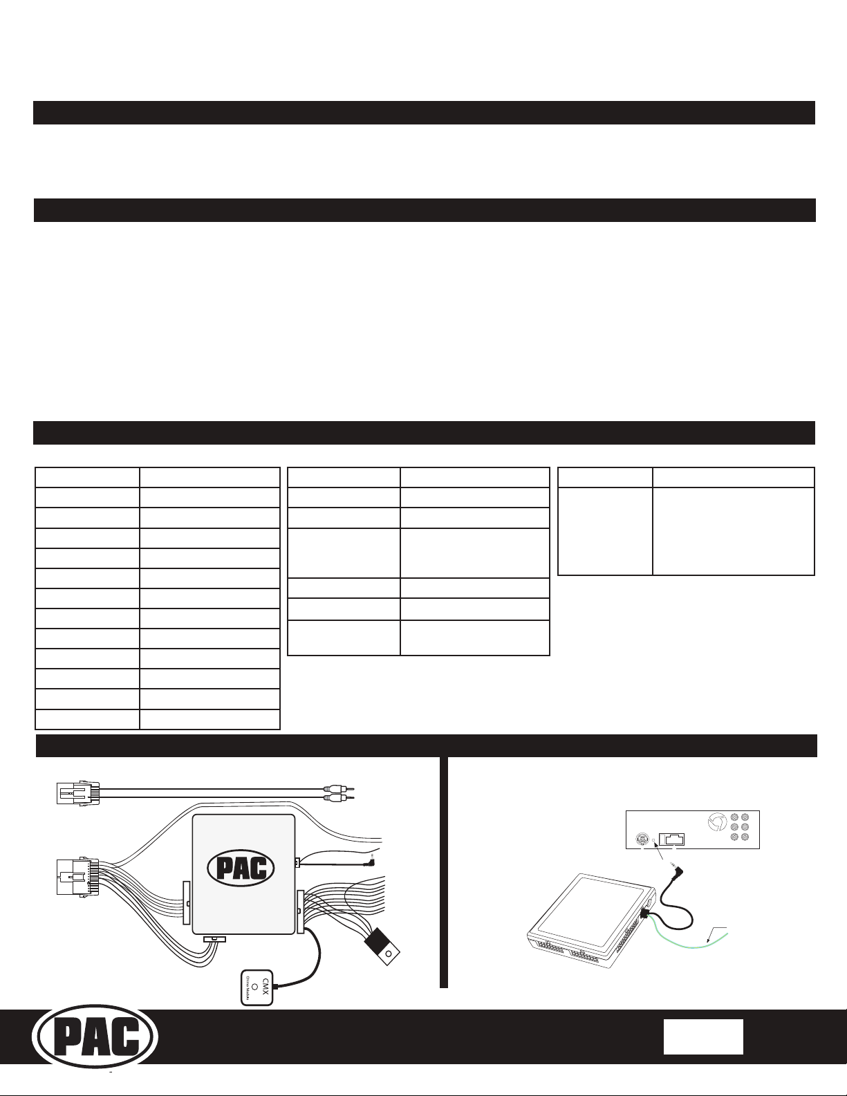
Radio Replacement& Steering Wheel Control Interface
with OnStar Retention for General Motors Vehicles
RP5-GM11
© 2018 AAMPGlobal. All rights reserved. PAC is a Power Brand ofAAMPGlobal.
PAC-audio.com
P ifi A C ti
Page 3
Rev: 5
Date: 050918
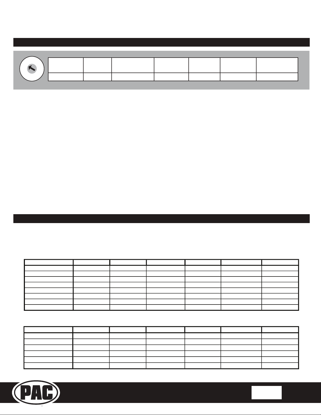
Optional Steering Wheel Control Programming
Alpine JVC Kenwood Clarion Other * Pionee
r
Son
y
Fusion
1 Volume + Volume + Volume + Volume + Volume + Volume + Volume + Volume +
2 Volume - Volume - Volume - Volume - Volume - Volume - Volume - Volume -
3 Mute Mute Mute Mute Mute Mute Mute Mute
4 Preset + Source Source Source Preset + Preset + Preset + Source
5 Preset - Track + Pla
y
Search + Preset - Preset - Preset - Track +
6 Source Track - Track + Search - Source Source Source / End Call Track -
7 Track + Band / Disc + Track - Band Track + Track + Track + Audio
8 Track - Preset / Disc - Disc / FM + Send / End Track - Track - Track - Powe
r
9 Powe
r
Select Disc / AM - Send Band Band Band
10 Enter / Pla
y
Attenuation Answe
r
End Answer ** Phone Menu Power / End Call
11 Band / Pro
g
ram Phone Receive Voice Voice End ** Answer Call Voice / Answer / End Call
12 Receive Phone Reject On Hook PTT ** End Call Voice (Android Auto & Car
Pla
y)
Answer / End Call***
13 End Voice Off Hook Voice
14 Voice Powe
r
Mute
15 Preset +
* Dual / Axxera, Jensen, Rockford Fosgate ** Jensen ONLY ***
XAV-AX100 / 200 Only
Optional Programming Order
Programming
1. Turn the key to the ignition position.
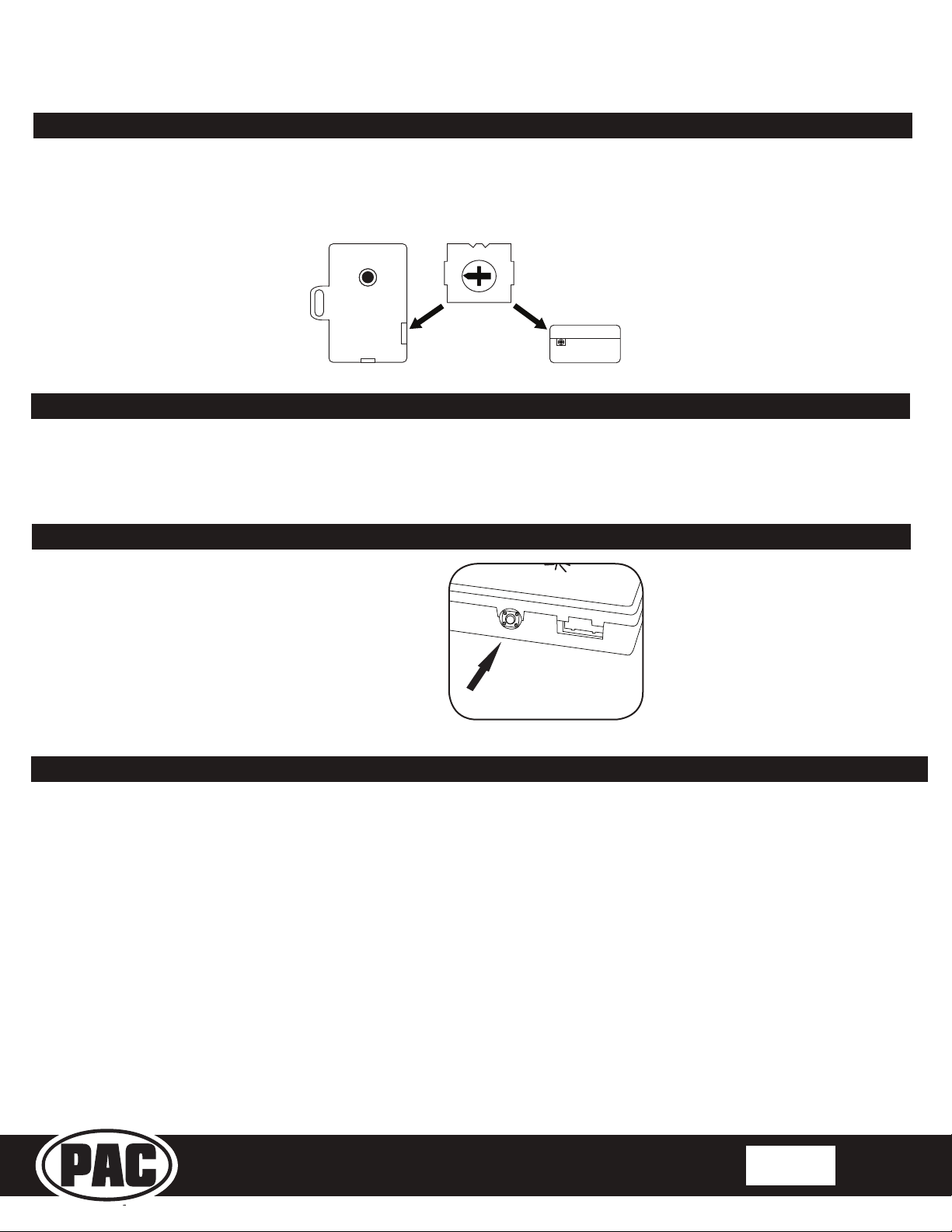
2. Press and release programming button on the side of the interface.
3. Within 7 seconds, press the button that is to be learned on the steering wheel. The LED will turn off when the button is pressed.
4. If you need to program more buttons, repeat step 3 for each additional audio function on the steering wheel.
5. If you come across a function in the chart that your steering wheel does not have, or you do not want to program, press and
release the program button on the side of the interface to skip that function.
6. 2QFHSURJUDPPLQJLVFRPSOHWHGZDLWVHYHQVHFRQGV7KH/('ZLOOÀDVKWKUHHWLPHVLQGLFDWLQJHQGRISURJUDPPLQJ
7. Test the interface for proper functionality. Whenever a SWC is pressed the LED on the interface should blink. If any function
does not work, repeat the programming steps.
,I\RXZLVKWRUHDVVLJQWKH6:&IXQFWLRQVWKHLQWHUIDFHPXVWEHSURJUDPPHGLQWKHVSHFL¿FRUGHUVKRZQRQWKHFKDUWEHORZ,I
you come across a function in the chart that your steering wheel does not have, or you do not want to program, press and release
WKHSURJUDPPLQJEXWWRQRQWKHVLGHRIWKHLQWHUIDFHWRVNLSWKDWIXQFWLRQ7KH/('ZLOOÀDVKRIIDQGRQFRQ¿UPLQJWKDW\RXKDYH
successfully skipped that function and are ready to proceed to the next one.
7HVWLQJDQG9HUL¿FDWLRQ
1. Turn the ignition on. The LED on the interface will turn on and the +12v accessory wire will turn on.
2. Turn on the radio and check balance and fade. Note: 3UHPLXP)DFWRU\DPSOL¿HG6\VWHPV will not fade as neither the
DIWHUPDUNHWUDGLRRUWKH53LQWHUIDFHKDYHWKHDELOLW\WRFRQWUROWKHDPSOL¿HU¶VIDGHU
3. Verify that the factory subwoofer (if present) is playing.
4. Verify that all SWC are functioning properly for both the aftermarket radio and OnStar. To adjust OnStar volume, press the
OnStar button on the mirror then use the volume buttons on the SWC to adjust the level. The volume will raise a total of 8
times before returning to the original level.
5. Pressing the OnStar button on the rearview mirror will turn off the rear speakers and allow the OnStar audio to be heard in
the two front speakers. The OnStar active LED will also turn on. When OnStar disconnects, the radio will un-mute or turn
back on and the OnStar LED will turn off. Pressing the Mute/OnStar button on the steering wheel for 1.5 seconds will also
activate Onstar.
6. Turn off vehicle and remove key. RAP will be active and keep the radio on for 10 minutes or until the drivers door is opened.

Radio Replacement & Steering Wheel Control Interface
with OnStar Retention for General Motors Vehicles
RP5-GM11
© 2018 AAMP Global. All rights reserved. PAC is a Power Brand of AAMP Global.
PAC-audio.com
P ifi A C ti
Page 4
Rev: 5
Date: 050918
7HVWLQJDQG9HUL¿FDWLRQFRQW
7. The LED and radio will turn off when RAP turns off or the drivers door is opened.
8. Use the 4-position selector switch located on the side ofthe CMX module to selectthe bestchime outputvolume for your
VSHFL¿FLQVWDOODWLRQ6HWWLQJEHLQJORXGHVWDQGVRIWHVW
Rear SeatEntertainment(RSE); Ifequipped
The factory RSE system will function independently from the aftermarketradio. The unit will power up and pass audio through
the headphones as long as the vehicle’s ignition is on. Ifyou wish to pass audio from the RSE to the aftermarketradio you must
connectthe RCAs from the 12-pin connector to the aftermarketradios auxiliary input. Selectthe aftermarketradios auxiliary input
to hear RSE audio.
OnStar Volume Adjustmentfor Vehicles w/o SWC
1. IfSWCbuttons are notpresentyou mustuse the
programming button on the interface to control the OnStar
audio level during an OnStar connection.
2. When OnStar is active pressing the programming button
will raise the audio level 8 times before returning to the
original level. Every time the button is pressed a
FRQ¿UPDWLRQEHHSZLOOEHKHDUG
x3
Press the programming button
on the side ofthe interface while
OnStar is active to adjustthe
OnStar volume
CMX
chime module
1
4
2
3
Technical Supportand ProductUpdates (Firmware)
7KH53*0FDQEHXSGDWHGZLWKQHZ¿UPZDUHDVLWEHFRPHVDYDLODEOHXVLQJWKH3$&83LQWHUIDFHXSGDWHUVROGVHSDUDWHO\
3OHDVHYLVLWZZZ3$&DXGLRFRP¿UPZDUHIRUDYDLODEOHXSGDWHV
Technical Support
support@PAC-audio.com
866-931-8021

IMPORTANT INSTRUCTIONS FOR DOUBLE DIN RADIOS
When installing a high-power double-DIN radio, we recommend making the following connections on the
RPS
harness to ensure the interface and radio will perform correctly. Failure to do these steps, may result
in
loss
of
accessory power output from the RadioPRO module.
During this modification you will add two new wire leads, providing additional power and ground paths for the
aftermarket radio. These wires will remove the high power demand from the
RPS
module, and ensure proper
12 volt accessory operation.
NOTE:
We advise making all connection points secure by soldering or usi
ng
crimp terminals, and insulating appropriately.
'
Connection points ("A" and "B") at the vehicle connector(s) on the RadioPR05 harness
1) Locate the Yellow
12
volt constant power wire
by the vehicle connector
on
the
RPS
harness.
a.
Carefully cut the insulation, and expose a small portion of the wire.
We will call this connection point "Point
A"
2) Locate the Black ground wire
by the vehicle connector on the
RPS
harness.
a.
Carefully cut the insulation, and expose a small portion of the wire.
We will cali this connecti
on
point "Point B"
Connection points ("C" and "D") at the input side
of
the micro relay on the RadioPR05 harness
3)
Locate the Yellow 12 volt constant power wire
by the input side
of
the micro relay on the RP5 harness.
a.
Carefully cut the insulation, and expose a small portion
of
the wire.
We will call this connection point "Point C"
4) Locate the Black ground wire
by the input side
of
the micro relay
on
the RP5 harness.
a.
Carefully cut the insulation, and expose a small portion
of
the wire.
We will call this connection point "Point D"
© 2017 AAMP Global. All nghts reserv
e~.
PAC
Is
a Power Brand
of
AAMP Global. -
PAC-
au~10
.com
Email -support@PAC-aud10 c
bm
-Toll Free: 866-931-8021

IMPORTANT INSTRUCTIONS FOR DOUBLE DIN RADIOS
Adding additional
15"
wires
to
jump power
and
ground
5) Connect a 15" lead of Yellow wire (any color will work) to Point
A.
6) Connect the other end ofthis wire to the Yellow input wire
on
the micro relay (Point C)
Ensure your connection points are insulated properly.
7) Connect a 15" lead of Black wire (any color will work) to Point
B.
8) Connect the other end ofthis wire to the Black input wire
on
the micro relay (Point
D)
Ensure your connection points are insulated properly.
Once the constant power and ground leads are connected and effectively bypass the RadioPR05
module, the modification
is
complete.
At this point the module can
be
installed into the vehicle per normal installation instruction.
© 2017 AAMP Global. All rights reserved.
PAC
Is
a Power Brand ofAAMP Global -
PAC-a~d10
com
Email -support@PAC-aud1o.com -Toll Free: 866-931-8021
Table of contents
Other PAC Recording Equipment manuals

PAC
PAC OS2-GM32X User manual

PAC
PAC RP5-GM11 User manual

PAC
PAC RadioPRO 5 RP5-GM41 User manual

PAC
PAC NU-GM4 User manual

PAC
PAC OS-5 User manual

PAC
PAC neprox 500 Series User manual

PAC
PAC RP4.2-TY13 User manual

PAC
PAC RSIC-SI-CRC EZ User manual

PAC
PAC APSUB-GM61 User manual

PAC
PAC RP5-GM31 Reference manual