elobau eloFlex 471EFR Series Quick guide

Art.-Nr./Art. No./Réf./N° art/N° art.: 9010008B01M Version: 1.3 Date: 29.08.2017 1/9
Safety control unit eloFlex 471EFR
Translation of the original operating instructions
Table of contents
1About these operating instructions .......................................................1
2Designated use.....................................................................................1
3Approvals..............................................................................................1
4Safety information.................................................................................1
5Warning against misuse .......................................................................1
6Exclusion of liability ..............................................................................2
7Function................................................................................................2
8Technical specifications........................................................................2
9Installation ............................................................................................2
10 Electrical connection.............................................................................3
11 Commissioning.....................................................................................3
12 Maintenance.........................................................................................3
13 Troubleshooting....................................................................................3
14 Disposal................................................................................................3
Declaration of conformity ................................................................................9
GB
1 About these operating instructions
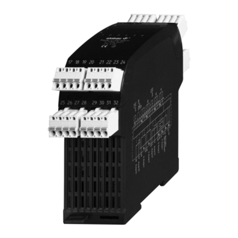
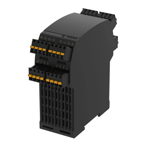
The following eloFlex standard models are described:
- 471EFR2D14K_ SIL2/PLd with 4 safety outputs
- 471EFR3E14K_ SIL3/PLe with 4 safety outputs
- 471EFR3E13K_ SIL3/PLe with 3 safety outputs
- 471EFR3E12K_ SIL3/PLe with 2 safety outputs
- 471EFR3E11K_ SIL3/PLe with 1 safety output
Refer to the data sheet for the chosen configuration.
Data sheets can also be requested from elobau for customer-specific safety
control units. The information specified in the data sheet applies for customer-
specific models if this information deviates from the operating instructions.
The person installing the safety control unit must be provided with the operat-
ing instructions.
The operating instructions and data sheet must be kept in a legible condition
and in an accessible location.
Meaning of the symbols used:
Warning
Failure to observe this warning may result in faults or malfunc-
tions.
Failure to observe this warning may result in personal injury
and/or damage to the machine.
Information
Indicates available accessories and useful additional informa-
tion.
2 Designated use
The safety control unit is part of the overall system or machine and is for the
purpose of assuming safety-related functions.
This is done by monitoring signals, for example safety sensors, emergency-
stop buttons, position switches, no-contact protective equipment (BWS). The
product must be used only in accordance with the descriptions below.
3 Approvals
[AUXILIARY DEVICE]
E334998
4 Safety information
- Ensure that the safety control unit is installed and put into oper-
ation only by specially trained, authorized personnel.
- Only install and put the device into operation once you have
read and understood the operating instructions and are familiar
with the applicable regulations on occupational safety and acci-
dent prevention.
- Ensure that the corresponding fuses (see "Technical specifica-
tions") are used. Never bypass or repair any fuses.
- Ensure that the safety control unit is only used to protect against
dangers.
- Ensure that all applicable safety requirements for the machine in
question are observed.
- Ensure that all applicable European directives and national
laws/directives are observed.
-
-
Ensure that the control output is only used for displaying the op-
erational status of the safety control unit.
There are no known residual risks, if all of the information con-
tained in these operating instructions is complied with.
5 Warning against misuse
- In case of improper or unintended use or manipulation, dangers
for personnel and damage to the machine or system compo-
nents cannot be excluded by the use of the safety control unit.
Please also observe the relevant information stipulated
ISO 14119.
- Make sure that no current or voltage peaks that are higher than
the electrical specifications of the safety control unit are caused
by any external components. Current or voltage peaks are pro-
duced, for example, by capacitive or inductive loads.
- Exceeding the electrical specifications of the safety control unit
(e.g. in the event of defective wiring or short circuits) can
damage the system irreparably. Non-compliance may result in
reduced service life.

Art.-Nr./Art. No./Réf./N° art/N° art.: 9010008B01M Version: 1.3 Date: 29.08.2017 2/9
6 Exclusion of liability
No liability shall be accepted for any damage or operational faults caused by
a failure to observe these operating instructions. All further liability of the
manufacturer is excluded in the case of damage caused by the use of
replacement and accessory parts that have not been authorized by the
manufacturer.
No unauthorized repairs, conversions or modifications are permitted for reasons
of safety and the manufacturer shall not be liable for any resulting damage.
7 Function
4 safety inputs safety inputs, that can be connected differently, connect the
safety and control outputs respectively depending on the configurable, logical
connection. In addition, there are two inputs available for reading external con-
tactors and start buttons.
Refer to the associated data sheet for the exact configuration.
Configuration options
On our website www.elobau.com eloFlex you will find the eloFlex Configura-
tor, which offers a step-by-step guide to derive your required configuration.
Clicking on underlined terms and functions serves to open an explanatory win-
dow to explain the items in more detail.
The micro-controller-controlled safety control unit can be delivered with the fol-
lowing configuration options.
Each component can be individually customised.
If an OSSD safety input is chosen, the (+) potential must be taken from termi-
nals 8, 16, 24, 32.
Upon selection of OSSD at the safety input a sensor with cross-short detec-
tion must be used or any errors resulting from cross-shorts must be ruled out.
A maximum of one external contactor input can be assigned to one safety
output.
Safety input 1-4
(NO/NO) (-/+) e.g. protective door
(NO/NC) PL e (+/+) / PL d (-/+) e.g. protective door
(NC/ NC) (-/+) emergency stop switch
OSSD (safe semiconductor) (+/+) safe sensors only with PNP
outputs e.g. light grid
External contactor /Start 1-2
automatic Automatic start/restart with HIGH level
manual Release at rising flank
manual Release at falling flank
Safety output 1-4
Input Logic * Switch-on/switch
off delay in s
External monitoring
Safety input 1 AND tON
, s
___
tOFF
, s
Contactor/
start 1
Safety input 2 OR Contactor/
start 2
Safety input 3 NAND
Safety input 4 NOR
XOR
XNOR
NOT
2-hand safety control 1 + 2
2-hand safety control 3 + 4
* When selecting the logic operator, ensure that the resulting function fulfils the
specified safety function and corresponds to the specified properties.
* Th control output is switched on after initialization.
No input is assigned when selecting BTR, error or safety output. The outputs’
switch-on/switch-off delay time of between 0.0 s and 99.9 s can be set in
0.1 second steps.
LED displays
Control outputs 1-4
Input Logic Switch-on/switch-off
delay in s
AND tON
, s
___
tOFF
, s
OR
NAND
Safety input 1
Safety input 2
Safety input 3
Safety input 4 NOR
XOR
XNOR
NOT
BTR*
ERROR
as for safety output 1
as for safety output 2
as for safety output 3
as for safety output 4
1
3
7
4
8
5
9
6
10
2
LED 1
LED 2
LED 3
LED 4
LED 5
LED 6
LED 7
LED 8
LED 9
Operability ("Ready")
Fault ("Error")
Safety input 1 ("I 1")
Safety input 2 ("I 2")
Safety input 3 ("I 3")
Safety input 4 ("I 4")
Safety output 1 ("O 1")
Safety output 2 ("O 2")
Safety output 3 ("O 3")
LED 10 Safety output 4 ("O 4")
Operating time
The operating time is the maximum time permitted on a sensor between actua-
tion of both sensor contacts.
With 2-hand operation, it is the maximum time permitted between actuation of
both sensors.
Safe condition
The safety outputs are opened or with high resistance.
Hazardous condition
The safety outputs are closed or with low resistance.
8 Technical specifications
See "Technical specifications" from page 15.
9 Installation
- Installation of the safety control unit is only permitted in a voltage-free state.
- Ensure that the prescribed fuses (see "Technical specifications") are used.
- Snap the safety control unit onto a mounting rail (DIN EN 60715 TH35) in the
switch cabinet. The safety control unit is fixed.
- Connect the safety control unit.
The pluggable terminal blocks can be coded by means of pins, the sockets
in the device are inversely coded by means of coding tabs.
Danger
Danger of electrocution!
Ensure that the safety control unit is installed and put into
operation only by specially trained, authorized personnel.

Date: 29.08.2017 3/9
- If the safety input remains free:
Ensure that the contact makers of this safety input are bridged.
10 Electrical connection
- Electrical connection is only permitted in a voltage-free state.
- Make sure that the details described in the technical specifications are al-
ways complied with.
- Measures to improve the equipment’s immunity to interference from line-
conducted and radiated high frequency interference are to be taken
(DIN EN 60204-1:2007-06, para 4.4.2).
When connecting the sensor, the sensor power supply voltage (+) and (-)
terminals identified in the technical specifications are to be used.
Terminal connections
11 Commissioning
In random order:
- Damp safety sensors.
- Apply operating voltage.
- Then actuate the start button if necessary.
The LEDs of the inputs and outputs used and the "Ready" LED light up.
The safety control unit is ready. The safety control unit switches through the
safety output.
Art.-Nr./Art. No./Réf./N° art/N° art.: 9010008B01M Version: 1.3
Accessories
Spring terminals are supplied as standard (order number
878598).
Optional screw terminals (order number 878719) and dou-
ble terminals (order number 878717) are available from
elobau.
A corresponding coding tab set is available from elobau un-
der order number 350SAE001.
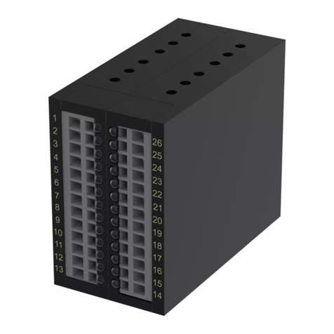
Components Terminals Explanation
Safety input 1 5-8 Depending on configuration, the inputs at
terminals 5, 13, 21, 29 (+) or (-) are read-
only.
Connection options:
- Sensors with 2-NO system
- Sensors with NO/NC System
- Emergency stop push button
- 2-hand control
- Light grid (OSSD)
- Photoelectric sensor (OSSD)
Safety input 2 13-16
Safety input 3 21-24
Safety input 4 29-32
Safety output 1 1, 25
Switching dependent on
- Safety input 1-4
- Logic
- Switch-on/switch-off delay (optional)
- Contactor/start inputs (optional)
Safety output 2 2, 26
Safety output 3 3, 27
Safety output 4 4, 28
External contactor/
Start 1-2
11, 12 External contactor and/or start button
(automatic, manual or monitored)
Operating voltage 9, 10
Control output 1 17 Not suitable for safety functions!
Switching dependent on
- Safety input 1-4
- Logic
- Switch-on/switch-off delay times
(optional)
Control output 2 18
Control output 3 19
Control output 4 20
Danger
Danger of electrocution!
Ensure that the safety control unit is installed and put into
operation only by specially trained, authorized personnel.
NOTE
Make sure that no external voltage is applied to the safety
inputs when the operating voltage is applied (e.g. by devic-
es with OSSD outputs).
12 Maintenance
Each safety circuit must be checked by specially trained, authorised personnel
in accordance with national regulations within the time-limits specified therein.
(Recommendation: in accordance with application as per EN ISO 14119)
13 Troubleshooting
- If the ready LED and the LEDs of the applied inputs light up, the outputs flash
and the error LED is off, then the safety control unit is waiting for the start
signal at input "ext. contactor /start" (see also item 13 "Troubleshooting").
NOTE
Upon initial commissioning of a safety control unit with a
new configuration, complete validation according to the rel-
evant standards must be carried out.
LEDs eloFlex
Meaning Remedy
Ready
Error
I1
I2
I3
I4
O1
O2
O3
O4
Normal operation —
Operating time
exceeded, only
affected input(s)
will flash
Open and close
the door. If error
persists, replace
the sensor/
switching device
Internal fault
Apply the supply
voltage again².
If error persists,
replaceswitching
device
11Input(s)
available, start
expected
Check the
feedback loop:
Is the start signal
at the input start
1/2 (terminal 11/
12) available?
14 Disposal
Dispose of packaging and used parts in accordance with the regulations of the
country in which the device is installed.
Legend
LED on
LED off
LED flashes
LED arbitrary state
Number of lit/flashing LEDs is dependent on the configuration of the
eloFlex
Ensure that no external voltages are in contact with the inputs during
a voltage reset (e.g. from devices with OSSD outputs)
1
2

Art.-Nr./Art. No./Réf./N° art.: 9010008B01M Version 1.3 Date: 29.08.2017 4/9
Technical specifications
Installation dimensions eloFlex
471EFR2D...
eloFlex
471EFR3E...
Housing excluding terminals 120 x 100 x 45 mm
Housing with terminals120 x 130 x 45 mm
Mechanical characteristics eloFlex
471EFR2D...
eloFlex
471EFR3E...
Housing PA, PC black
Max. weight (differs depending on
configuration) 400 g
Protection class IP 30 DIN EN 60529
Protection class of installation
space IP 54 DIN EN 60529
Physical characteristics eloFlex
471EFR2D...
eloFlex
471EFR3E...
Relative humidity 5% ... 85%
Air pressure 860 ... 1060 hPa
Δtmax 0,5 °C/min
Operating temperature -15 ... +55 °C -15 ... +55 °C
Transport and storage
temperature -40 ... +70 °C -25 ... +70 °C
Electrical characteristics eloFlex
471EFR2D...
eloFlex
471EFR3E...
Fuse for operating voltage
(fast-acting) 1A
Safety output fuse 3 A
Operating voltage 24 V DC ± 10%
Max. current consumption 800 mA
Status display 10x LED
Max. switching voltage
safety outputs 1-4 250 V AC / 30 V DC
Max. switching current
safety outputs 1-4 3 A AC/DC
Max. switching capacity
safety outputs 1-4 750 VA / 90 W
Max. switching voltage
control outputs 1-4 24 V DC ± 10%
Max. switching current
control outputs 1-4 100 mA
Max. number of switching
operations at 0.5 A switching
current (ohmic load)
1 x 1063 x 106
Max. number of switching
operations at 3 A switching
current (ohmic load)
1,9 x 1052,8 x 105
Usage category pursuant to
EN 60947-5-1 / AC-15 250 V AC / 3 A 250 V AC / 3 A
Usage category pursuant to
EN 60947-5-1 / DC-13 24 V DC / 2 A 24 V DC / 3 A

Art.-Nr./Art. No./Réf./N° art.: 9010008B01M Version: 1.3 Date: 29.08.2017 5/9
Safety-related characteristics1) eloFlex
471EFR2D...
eloFlex
471EFR3E...
SIL in accordance with
IEC/DIN EN 61508
2 3
SILCL in accordance with
IEC/DIN EN 62061
2 3
PL in accordance with
DIN EN ISO 13849-1
d e
Category according to
DIN EN ISO 13849-1
34
PFHD1,26 x10-8 1/h 3,28 x10⁻⁹ 1/h
Service life in years 20
Hardware fault tolerance (HFT) 1
Class B
Sensor contacts actuation
operating time (typical)
3 s
Operating time 2-hand control 0,5 s
Max. response time < 50 ms
1) Additional safety-related
characteristics on request.
Terminal connections eloFlex
471EFR2D...
eloFlex
471EFR3E...
Operating voltage 9, 10
Sensor power supply voltage (+) 8, 16, 24, 32
Sensor power supply voltage (-) 6, 14, 22, 30
Safety input 1 5, 7
Safety input 2 13, 15
Safety input 3 21, 23
Safety input 4 29, 31
Safety output 1 1, 25
Safety output 2 2, 26
Safety output 3 3, 27
Safety output 4 4, 28
EDM/Start 1-2 11, 12
Terminal connections eloFlex
471EFR2D...
eloFlex
471EFR3E...
Control output 1 17
Control output 2 18
Control output 3 19
Control output 4 20

Art.-Nr./Art. No./Réf./N° art.: 9010008B01M Version: 1.3 Date: 29.08.2017 6/9
Mechanical design

Art.-Nr./Art. No./Réf./N° art.: 9010008B01M Version: 1.3 Date: 29.08.2017 7/9
Circuit diagram
Attention! Illustrative wiring to PL e Attention! Illustrative wiring to PL d
Circuit diagram is available for the each standard model (see item 1 “About these operating instructions” on page 4) variant on request.

998H0007K0006
elobau GmbH & Co. KG
Zeppelinstraße 44
D-88299 Leutkirch
+49-7561-970-0 / www.elobau.de
EU-Konformitätserklärung
EU- Declaration of Conformity
Hiermit erklären wir, dass das nachfolgend aufgeführte Produkt aufgrund der Konzipierung und
Bauart den Sicherheits- und Gesundheitsanforderungen der unten genannten EU-Richtlinien
entspricht.
Hereby we officially validate that the below listed component comply with the requirements of the following European Directive because of their
design and construction:
Bezeichnung des Bauteils:
Name of component:
eloFlex
Beschreibung des Bauteils:
Description of component:
konfigurierbares Sicherheitssystem
configurable safety related system
elobau Artikel-Nr.:
elobau item no.:
471 EFR 2D1 4K*
471 EFR 3E1 4K*
471 EFR 3E1 3K*
471 EFR 3E1 2K*
471 EFR 3E1 1K*
Einschlägige EU-Richtlinien:
Relevant EC-Directives:
harmonisierte Normen:
harmonized standards:
nicht harmonisierte Normen:
not harmonized standards:
Maschinenrichtlinie 2006/42/EG
EMV-Richtlinie 2014/30/EU
Machinery Directive 2006/42/EC
EMC Directive 2014/30/EU
EN 62061:2016 + Cor. :2010 + A 1 :2013 + A2:2015
EN ISO 13849-1:2015
EN 61000-6-2: 2006
EN 61000-6-3: 2007+ A1: 2011
IEC 61508 – Reihe
DIN EN 61326-3-1: 2008
Ä
nderungsindex:
Modification Index:
D

998H0007K0006
Die Übereinstimmung eines Baumusters der Baureihe 471 EFR 2D14K* und 471 EFR 3E1*K* mit
der oben benannten Richtlinie wurde bescheinigt durch:
The consistency of a production sample with the marked product in accordance with the above named Directive has been certified
by:
Name und Anschrift
benannte Stelle:
TÜV SÜD Product Service GmbH
Ridlerstraße 65
D-80339 München
Kennnummer: 0123
Nummerierung der
Bescheinigung:
Certification number:
M6A 17 11 20166047
Leutkirch, den 06.12.2017
Sandrina Kratzer
CE-Beauftragte /
EC authorized Representative
Dokumentation-Bevollmächtigte /
Documentation Representative
Sa
Sa
S
S
S
S
S
S
S
S
S
S
S
S
S
S
S
S
S
S
S
S
S
S
S
S
S
S
S
nd
nd
d
nd
d
nd
d
d
d
d
ri
ri
i
r
r
r
na
na
na
a
a
a
K
K
K
K
K
K
K
K
K
K
ratzer
Other manuals for eloFlex 471EFR Series
2
Table of contents
Other elobau Control Unit manuals
Popular Control Unit manuals by other brands
Alfalaval
Alfalaval SRC PN10 instruction manual

Delta
Delta MultiChoice Ara T27T867 Series owner's manual

Qcells
Qcells Q.PEAK DUO BLK ML-G10/t Series Installation and operation manual
Intelligent Lighting Controls, Inc.
Intelligent Lighting Controls, Inc. LightLEEDer BACnet Configurations
Keyautomation
Keyautomation CT1RD Instructions and warnings for installation and use
SimCom
SimCom SIM900B EVB Hardware design
