elobau 363 098 User manual

1 Bestimmungsgemäßer Einsatz
Varianten 363 098, 363 V98, 363 V99, 364 097, 462 009 R
Die Schnittstelle dient zur Verknüpfung mehrerer elobau Sensoren mit einer elobau
Auswerteeinheit.
Variante 363 R98
Die Schnittstelle dient zur Verknüpfung mehrerer elobau Verriegelungen mit einer elobau
Auswerteeinheit.
Sicherheit/Gefahren
- Sicherstellen, dass die Schnittstelle nur von speziell ausgebildetem, autorisiertem Personal montiert
und in Betrieb genommen wird.
- Schnittstelle nur in unversehrtem Zustand betreiben.
- Sicherstellen, dass die Schnittstelle ausschließlich zum Schutz vor Gefährdungen eingesetzt wird.
- Sicherstellen, dass alle geltenden Sicherheitsbestimmungen der entsprechenden Maschine
eingehalten werden.
- Sicherstellen, dass alle geltenden europäischen Richtlinien und nationalen Gesetze/Richtlinien
eingehalten werden.
2Funktion
Variante 363 098
Die Schnittstelle verknüpft maximal 4 Sensoren mit Schließer- und Öffnerkontakt.
Bei Anschluss von mehr als 4 Sensoren:
- Weitere Schnittstelle zur vorherigen parallel schalten.
Die entsprechende LED leuchtet, wenn ein angeschlossener Sensor entdämpft ist.
Variante 363 R98
Die Schnittstelle verknüpft maximal drei Verriegelungen.
- Nur in Verbindung mit elobau Sensoren 118 HVE 01 verwenden.
Bei Anschluss von weniger als 3 Verriegelungen:
- Freie Klemmen der Schließer- und Bolzenkontakte überbrücken.
Die erste LED leuchtet, wenn der Bolzen einer angeschlossenen Verriegelung eingerastet ist.
Die zweite LED leuchtet, wenn die Bolzen zweier angeschlossener Verriegelungen eingerastet sind.
Die dritte LED leuchtet, wenn die Bolzen aller angeschlossenen Verriegelungen eingerastet sind.
Varianten 363 V98 und 363 V99
Die Schnittstelle verknüpft maximal 8 Sensoren mit Schließerkontakten.
- Nur in Verbindung mit elobau Sensoren verwenden, die V62 an der 4. bis 6. Stelle aufweisen (siehe
Typenbenennung/Varianten der Sensoranleitung).
Bei Anschluss von weniger als 8 Sensoren:
- Freie Anschlüsse vor dem letzten Sensor überbrücken.
- Rückführungen des letzten Sensors an die Klemmen 30 und 32 anschließen.
Variante 364 097
Die Schnittstelle verknüpft maximal 4 Sensoren mit Schließerkontakten.
- Nur in Verbindung mit elobau Sensoren verwenden, die 262 an der 4. bis 6. Stelle aufweisen (siehe
Typenbenennung/Varianten der Sensoranleitung).
Bei Anschluss von weniger als 4 Sensoren:
- Freie Klemmen der Schließerkette überbrücken.
Die entsprechende LED leuchtet, wenn ein angeschlossener Sensor bedämpft ist.
Variante 462 099 R
An die Schnittstelle können maximal 4 Sensoren mit Öffner- und Schließerkontakten angeschlossen
werden.
Der Kontrollausgang ist angezogen und die entsprechende LED leuchtet, wenn der entsprechende
Sensor entdämpft ist.
LED-Anzeigen
Variante 363 098
Variante 363 R98
Variante 364 097
Variante 462 099 R
Auswerteeinheiten
Folgende Auswerteeinheiten können angeschlossen werden:
3Montage
- Schnittstelle im Schaltschrank auf eine Hutschiene (DIN 50 022) aufschnappen.
Die Schnittstelle ist fixiert.
- Schnittstelle anschließen, siehe Technische Daten.
4 Inbetriebnahme
Die Schnittstelle schaltet ein, wenn ein angeschlossener Sensor bedämpft wird.
5 Störungsbeseitigung
Bei Funktionsstörung der Schnittstelle:
- Schnittstelle ersetzen.
EG-Konformitätserklärung
Wir erklären, dass die Schnittstellen 363 098, 363 R98, 363 V98, 363 V99, 364 097 und 462 099 R
die Konformität mit folgenden Richtlinien erfüllen:
98/37/EG, 2006/95/EG, 2004/108/EG
Angewandte harmonisierte Normen:
DIN EN 60204-1, DIN EN 61000-6-2, DIN EN 61000-6-4, DIN EN 954-1
LED Bedeutung bei leuchtender LED
S1 Sensor 1 entdämpft
S2 Sensor 2 entdämpft
S3 Sensor 3 entdämpft
S4 Sensor 4 entdämpft
LED Bedeutung bei leuchtender LED
H1 Riegel 1, Bolzen verriegelt
H2 Riegel 2, Bolzen verriegelt
H3 Riegel 3, Bolzen verriegelt
LED Bedeutung bei leuchtender LED
H1 Sensor 1 bedämpft
H2 Sensor 2 bedämpft
H3 Sensor 3 bedämpft
H4 Sensor 4 bedämpft
LED bei
Klemme Bedeutung bei leuchtender LED
7 Sensor 1 entdämpft
11 Sensor 2 entdämpft
16 Sensor 3 entdämpft
20 Sensor 4 entdämpft
D
Typen-Benennung Auswerteeinheit
363 098
462 099 R 462 12. G1.
462 121 E1.
462 121 H1.
463 12. ..
363 R98 462 M21 H31 01
363 V98
364 097 462 M41 H3.
462 M51 H.1
471 M41 H31
363 V99 462 111 B1
462 114 B1
470 111 B1
470 115 B1
Gefahr
Lebensgefahr durch Stromschlag!
Sicherstellen, dass die Schnittstelle nur von speziell ausgebildetem, autorisiertem
Personal montiert und in Betrieb genommen wird.
Gefahr
Lebensgefahr durch Stromschlag!
Sicherstellen, dass die Schnittstelle nur von speziell ausgebildetem, autorisiertem
Personal montiert und in Betrieb genommen wird.
Leutkirch, 12.06.2008 Werk:
Zeppelinstraße 44
88299 Leutkirch
Germany
Tel.: +49 7561 970-0
Fax: +49 7561 970-100
E-Mail: info@elobau.de
Web: www.elobau.com
Michael Hetzer,
Geschäftsführer
elobau
Elektrobauelemente GmbH & Co. KG
Postfach 1265
88306 Isny/Allgäu
Germany
363 098 / 363 R98 / 363 V98 / 363 V99 / 364 097 / 462 099 R

1 Appropriate use
Models 363 098, 363 V98, 363 V99, 364 097, 462 009 R
The interface serves to link several elobau sensors with one elobau control unit.
Model 363 R98
The interface serves to link several elobau locks with one elobau control unit.
Safety/Dangers
- Ensure that interface is only installed and put into operationby specially-trained authorised personnel.
- Only operate the interface when it is in an undamaged condition.
- Ensure that interface is only used for protection against dangers.
- Ensure that all safety requirements applying for the machine in question are observed.
- Ensure that all applicable European directives and national laws/directives are observed.
2Function
Model 363 098
The interface links up to 4 sensors with contact makers and contact breakers.
If more than 4 sensors are connected:
- Connect additional interface units in parallel.
The respective LED lights up, if a connected sensor is de-energized.
Model 363 R98
The interface connects up to three interlocks.
- Only to be used in conjunction with elobau sensors 118 HVE 01.
If less than 3 interlocks are connected:
- The contact maker and the pin contacts must be bridged.
The first LED lights up when the pin of a connected interlock has engaged.
The second LED lights up when the pins of two connected interlocks are engaged.
The third LED lights up when the pins of all connected interlocks are engaged.
Models 363 V98 and 363 V99
The interface links up to 8 sensors with contact makers.
- To be used only in conjunction with elobau sensors that have V62 as the 4th, 5th and 6th digits (see
Type denomination/Variants of the sensor instructions).
If less than 8 sensors are connected:
- Bridge unassigned connections before the last sensor.
- Connect returns of last sensor to clamps 30 and 32.
Model 364 097
The interface links up to 4 sensors with contact makers.
- To be used only in conjunction with elobau sensors that have 262 as the 4th, 5th and 6th digits (see
Type denomination/Variants of the sensor instructions).
If less than 4 sensors are connected:
- Bridge unassigned terminals of contact maker chain.
The respective LED lights up when a connected sensor is energized.
Model 462 099 R
Up to a maximum of 4 sensors having contact breakers and contact makers can be connected to this
interface unit.
The control output is activated and the respective LED is illuminated when the respective sensor is de-
energized.
LED displays
Model 363 098
Model 363 R98
Model 364 097
Model 462 099 R
Control units
The following control units can be connected:
3Installation
- Snap the interface onto a mounting rail (DIN 50 022) in the switch cabinet.
The interface is fixed.
- Connect interface, see Technical Data.
4 Putting into operation
The interface is activated when a connected sensor is energized.
5 Troubleshooting
If the interface shows any fault:
- Replace interface.
EC Declaration of conformity
We declare that the interfaces 363 098, 363 R98, 363 V98, 363 V99, 364 097 and 462 099 R
fulfil the conformity to the following guidelines:
98/37/EC, 2006/95/EC, 2004/108/EC
Related harmonized standards:
DIN EN 60204-1, DIN EN 61000-6-2, DIN EN 61000-6-4, DIN EN 954-1
LED Meaning when LED is lit
S1 Sensor 1 de-energized
S2 Sensor 2 de-energized
S3 Sensor 3 de-energized
S4 Sensor 4 de-energized
LED Meaning when LED is lit
H1 Interlock 1, pin locked
H2 Interlock 2, pin locked
H3 Interlock 3, pin locked
LED Meaning when LED is lit
H1 Sensor 1 energized
H2 Sensor 2 energized
H3 Sensor 3 energized
H4 Sensor 4 energized
LED at terminal Meaning when LED is lit
7 Sensor 1 de-energized
11 Sensor 2 de-energized
16 Sensor 3 de-energized
20 Sensor 4 de-energized
GB
Type denomination Control unit
363 098
462 099 R 462 12. G1.
462 121 E1.
462 121 H1.
463 12. ..
363 R98 462 M21 H31 01
363 V98
364 097 462 M41 H3.
462 M51 H.1
471 M41 H31
363 V99 462 111 B1
462 114 B1
470 111 B1
470 115 B1
Danger
Danger of electrocution!
Ensure that interface is only installed and put into operation by specially-trained
authorised personnel.
Danger
Danger of electrocution!
Ensure that interface is only installed and put into operation by specially-trained
authorised personnel.
Leutkirch, 12 June 2008 Factory:
Zeppelinstraße 44
88299 Leutkirch
Germany
Tel.: +49 7561 970-0
Fax: +49 7561 970-100
E-mail: info@elobau.de
Web: www.elobau.com
Michael Hetzer,
General Manager
elobau
Elektrobauelemente GmbH & Co. KG
Postfach 1265
88306 Isny/Allgäu
Germany

1 Utilisation conforme
Variantes 363 098, 363 V98, 363 V99, 364 097, 462 009 R
L’interface sert à relier plusieurs capteurs elobau sur une seule entrée d'une unité de
contrôle elobau.
Variante 363 R98
L’interface sert à relier plusieurs unités de verrouillage elobau sur une seule entrée d'une unité de
contrôle elobau.
Sécurité / dangers
- S'assurer que l'interface est uniquement montée et mise en service par du personnel spécialement
formé et autorisé.
- Ne faire fonctionner l'interface qu’en parfait état.
- S'assurer que l'interface est uniquement utilisée pour la protection contre les dangers.
- S'assurer que les consignes de sécurité en vigueur de la machine concernée sont respectées.
- S'assurerque lesdirectives européenneset leslois / directives nationales envigueur sont respectées.
2Fonction
Variante 363 098
L’interface relie un maximum de 4 capteurs avec contacts de travail et de repos.
En cas de raccordement de plus de 4 capteurs :
- Brancher d’autres interfaces en parallèle à la précédente.
La LED correspondante s’allume quand un capteur connecté est ouvert.
Variante 363 R98
L’interface relie un maximum de trois unités de verrouillage.
- À n’utiliser qu’en association avec les unités de verrouillage elobau 118 HVE 01.
Si moins de 3 unités de verrouillage sont utilisées :
- Ponter les bornes libres des contacts de travail.
La première LED s’allume quand le pêne ou la languette de l'une des unités de verrouillage est
engagé(e).
La deuxième LED s’allume quand les pênes ou les languettes de deux des unités de verrouillage sont
engagé(e)s.
La troisième LED s’allume quand les pênes ou les languettes de toutes les unités de verrouillage sont
engagé(e)s.
Variantes 363 V98 et 363 V99
L’interface relie un maximum de 8 capteurs avec contacts de travail.
- À n’utiliser qu’en association avec des capteurs elobau dont la terminaison est V62(position def d'une
référence abc def) (voir désignation du type/variantes dans les instructions sur les capteurs).
En cas de connexion de moins de 8 capteurs :
- Ponter les contacts de travail libres.
- Alternativement, relier les fils de retour du dernier capteurcâblé (disponible sur l'entrée libre suivante)
aux bornes 30 et 32.
Variante 364 097
L’interface relie un maximum de 4 capteurs avec contacts de travail.
- À n’utiliser qu’en association avec des capteurs elobau dont la terminaison est 262 (position def d'une
référence abc def) (voir désignation du type/variantes dans les instructions sur les capteurs).
En cas de connexion de moins de 4 capteurs :
- Ponter les contacts de travail livres.
La LED correspondante s’allume quand un capteur connecté est fermé.
Variante 462 099 R
Un maximum de 4 capteurs avec contacts de repos et de travail peuvent être connectés à l’interface.
La sortie de contrôle est activée et la LED correspondante s’allume quand lecapteur correspondant est
ouvert.
Affichages DEL
Variante 363 098
Variante 363 R98
Variante 364 097
Variante 462 099 R
Unités de contrôle
Les unités de contrôle suivantes peuvent être raccordées :
3Montage
- Attacher l'interface à un profilé chapeau (DIN 50 022) dans l'armoire de commande.
L'interface est fixée.
- Connecter l'interface, voir Caractéristiques techniques.
4 Mise en service
L’interface est activée quand un capteur connecté est fermé.
5 Suppression des pannes
En cas de dysfonctionnement de l’interface :
- Remplacer l’interface.
Déclaration de conformité CE
Nous déclaration que les interfaces 363 098, 363 R98, 363 V98, 363 V99, 364 097 et 462 099 R
satisfont à la conformité des directives suivantes :
98/37/CE, 2006/95/CE, 2004/108/CE
Normes harmonisées appliquées :
DIN EN 60204-1, DIN EN 61000-6-2, DIN EN 61000-6-4, DIN EN 954-1
DEL Signification de la DEL allumée
S1 Capteur 1 ouvert
S2 Capteur 2 ouvert
S3 Capteur 3 ouvert
S4 Capteur 4 ouvert
DEL Signification de la DEL allumée
H1 Verrou 1, pêne verrouillé
H2 Verrou 2, pêne verrouillé
H3 Verrou 3, pêne verrouillé
DEL Signification de la DEL allumée
H1 Capteur 1 fermé
H2 Capteur 2 fermé
H3 Capteur 3 fermé
H4 Capteur 4 fermé
DEL de la
borne Signification de la DEL allumée
7 Capteur 1 ouvert
11 Capteur 2 ouvert
16 Capteur 3 ouvert
20 Capteur 4 ouvert
F
Désignation du type Unité de contrôle
363 098
462 099 R 462 12. G1.
462 121 E1.
462 121 H1.
463 12. ..
363 R98 462 M21 H31 01
363 V98
364 097 462 M41 H3.
462 M51 H.1
471 M41 H31
363 V99 462 111 B1
462 114 B1
470 111 B1
470 115 B1
Danger
Danger de mort par électrocution !
S'assurer que l'interface est uniquement montée et mise en service par du
personnel spécialement formé et autorisé.
Danger
Danger de mort par électrocution !
S'assurer que l'interface est uniquement montée et mise en service par du
personnel spécialement formé et autorisé.
Leutkirch, le 12.06.08 Usine :
Zeppelinstraße 44
88299 Leutkirch
Germany
Tél. : +49 7561 970-0
Fax : +49 7561 970-100
E-mail: info@elobau.de
Web: www.elobau.com
Michael Hetzer,
Gérant
elobau
Elektrobauelemente GmbH & Co. KG
Postfach 1265
88306 Isny/Allgäu
Germany
Art.-Nr./Art. No./Réf./N° art.: 900564 Version/Version/Version/Versione: 1.2 Datum/Date/Date/Data: 12.06.2008
1 Uso conforme alla destinazione
Versioni 363 098, 363 V98, 363 V99, 364 097, 462 009 R
L’interfaccia serve a combinare diversi sensori elobau con una unità di controllo elobau.
Versione 363 R98
L’interfaccia serve a combinare diversi finecorsa elobau con una unità di controllo elobau.
Sicurezza/pericoli
- Assicurarsi che l’interfaccia venga montata e messa in servizio esclusivamente da personale
specializzato, adeguatamente istruito ed autorizzato.
- Utilizzare l’interfaccia solamente in condizioni perfette.
- Assicurarsi che l’interfaccia venga utilizzata esclusivamente per laprotezione dasituazioni pericolose.
- Assicurarsi che vengano rispettate tutte le disposizioni di sicurezza della macchina.
- Assicurarsi che vengano rispettate tutte le direttive europee e le leggi/norme nazionali.
2 Funzione
Versione 363 098
L’interfaccia combina massimo 4 sensori con contatti NO e contatti NC.
Se sono collegati più di 4 sensori:
- Collegare le altre interfacce con parallelo con la precedente.
Il LED corrispondente si accende quando un sensore è stato disattivato.
Versione 363 R98
L’interfaccia combina massimo tre finecorsa con blocco.
- Utilizzare soltanto in combinazione con i sensori elobau 118 HVE 01.
Se sono collegati meno di 3 finecorsa con blocco:
- Cavallottare i morsetti liberi dei contatti NO e dei contatti a perno.
Il primo LED si accende quando i perni di un finecorsa con blocco sono in posizione di blocco.
Il secondo LED si accende quando i perni di due finecorsa con blocco sono in posizione di blocco.
Il terzo LED si accende quando i perni di tutti i finecorsa con blocco sono in posizione di blocco.
Versioni 363 V98 e 363 V99
L’interfaccia combina massimo 8 sensori con contatti NO.
- Utilizzare soltanto in combinazione con sensori elobau che nelle posizioni 4-6 indicano V62 (vedere
la denominazione dei tipi/varianti delle istruzioni del sensore).
Se sono collegati meno di 8 sensori:
- Ponticellare i collegamenti liberi prima dell’ultimo sensore.
- Collegare le retroazioni dell’ultimo sensore ai morsetti 30 e 32.
Versione 364 097
L’interfaccia combina massimo 4 sensori con contatti NO.
- Utilizzare soltanto in combinazione con sensorielobau che nelle posizioni 4-6 indicano 262 (vedere la
denominazione dei tipi/varianti delle istruzioni del sensore).
Se sono collegati meno di 4 sensori:
- Ponticellare morsetti liberi della catena di contatti NO.
Il LED corrispondente si accende quando un sensore collegato è attivato.
Versione 462 099 R
E’ possibile collegare massimo 4 sensori con contatti NC ed NO all’interfaccia.
L’uscita di controllo è attivata ed il LED corrispondente si accende quando il corrispondente sensore è
stato disattivato.
Indicazione LED
Versione 363 098
Versione 363 R98
Versione 364 097
Versione 462 099 R
Unità di controllo
E’ possibile collegare le seguenti unità di controllo:
3Montaggio
- Incastrare l’interfaccia nel quadro elettrico sulla guida (DIN 50 022).
L’interfaccia è fissata.
- Collegare l'interfaccia, vedi Specifiche tecniche.
4 Messa in funzione
L’interfaccia si attiva quando un sensore collegato è attivato.
5 Eliminazione dei disturbi
In caso di anomalia funzionale dell’interfaccia:
- Sostituire l'interfaccia.
Dichiarazione di conformità CE
Si dichiara che le interfacce 363 098, 363 R98, 363 V98, 363 V99, 364 097 e 462 099 R
soddisfano i criteri di conformità di cui alla presente direttiva:
98/37/CE, 2006/95/CE, 2004/108/CE
Norme armonizzate applicate:
DIN EN 60204-1, DIN EN 61000-6-2, DIN EN 61000-6-4, DIN EN 954-1
LED Significato a LED acceso
S1 Sensore 1 è disattivato
S2 Sensore 2 è disattivato
S3 Sensore 3 è disattivato
S4 Sensore 4 è disattivato
LED Significato a LED acceso
H1 Blocco 1, perno bloccato
H2 Blocco 2, perno bloccato
H3 Blocco 3, perno bloccato
LED Significato a LED acceso
H1 Sensore 1 attivato
H2 Sensore 2 attivato
H3 Sensore 3 attivato
H4 Sensore 4 attivato
LED del
morsetto Significato a LED acceso
7 Sensore 1 è disattivato
11 Sensore 2 è disattivato
16 Sensore 3 è disattivato
20 Sensore 4 è disattivato
I
Denominazione dei tipi Unità di controllo
363 098
462 099 R 462 12. G1.
462 121 E1.
462 121 H1.
463 12. ..
363 R98 462 M21 H31 01
363 V98
364 097 462 M41 H3.
462 M51 H.1
471 M41 H31
363 V99 462 111 B1
462 114 B1
470 111 B1
470 115 B1
Pericolo
Pericolo di morte dovuto a scosse elettriche!
Assicurarsi che l’interfaccia venga montata e messa in servizio esclusivamente da
personale specializzato, adeguatamente istruito ed autorizzato.
Pericolo
Pericolo di morte dovuto a scosse elettriche!
Assicurarsi che l’interfaccia venga montata e messa in servizio esclusivamente da
personale specializzato, adeguatamente istruito ed autorizzato.
Leutkirch, 12/06/2008 Fabbrica:
Zeppelinstraße 44
88299 Leutkirch
Germany
Tel.: +49 7561 970-0
Fax: +49 7561 970-100
E-Mail: info@elobau.de
Web: www.elobau.com
Michael Hetzer,
Direttore
elobau
Elektrobauelemente GmbH & Co. KG
Postfach 1265
88306 Isny/Allgäu
Germany
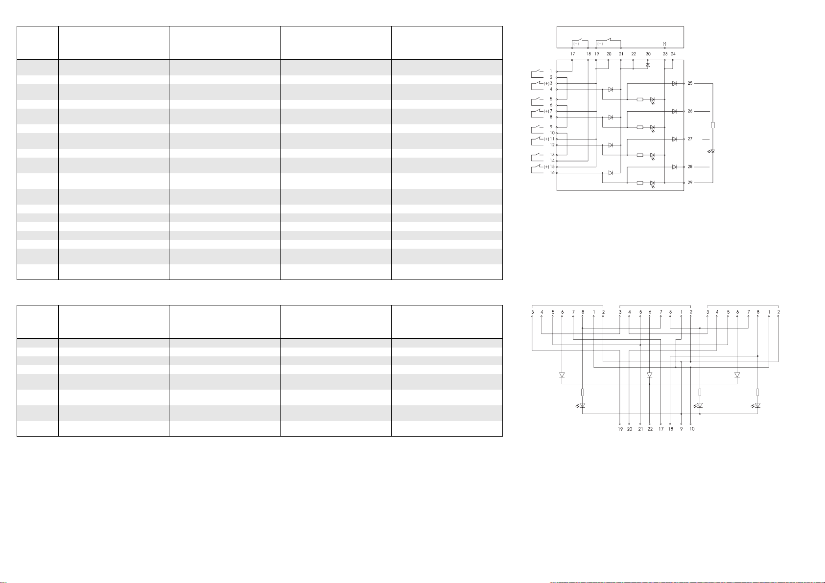
363 098
363 R98
Klemme
Terminal
Borne
Morsetto
Belegung Assignment Affectation Assegnazione
1, 2 Sensor 1, Schließerkontakt (wenn nicht
nötig: überbrücken) Sensor 1, contact maker (to be bridged, if
not needed) Capteur 1, contact de travail (si inutile :
ponter) Sensore 1, contatto NO (se non
necessario: cavallottare)
3, 4 Sensor 1, Öffnerkontakt Sensor 1, contact breaker Capteur 1, contact de repos Sensore 1, contatto NC
5, 6 Sensor 2, Schließerkontakt (wenn nicht
nötig: überbrücken) Sensor 2, contact maker (to be bridged, if
not needed) Capteur 2, contact de travail (si inutile :
ponter) Sensore 2, contatto NO (se non
necessario: cavallottare)
7, 8 Sensor 2, Öffnerkontakt Sensor 2, contact breaker Capteur 2, contact de repos Sensore 2, contatto NC
9, 10 Sensor 3, Schließerkontakt (wenn nicht
nötig: überbrücken) Sensor 3, contact maker (to be bridged, if
not needed) Capteur 3, contact de travail (si inutile :
ponter) Sensore 3, contatto NO (se non
necessario: cavallottare)
11, 12 Sensor 3, Öffnerkontakt Sensor 3, contact breaker Capteur 3, contact de repos Sensore 3, contatto NC
13, 14 Sensor 4, Schließerkontakt (wenn nicht
nötig: überbrücken) Sensor 4, contact maker (to be bridged, if
not needed) Capteur 4, contact de travail (si inutile :
ponter) Sensore 4, contatto NO (se non
necessario: cavallottare)
15, 16 Sensor 4, Öffnerkontakt Sensor 4, contact breaker Capteur 4, contact de repos Sensore 4, contatto NC
17, 18 Schließer-Ausgang für Auswerteeinheit Contact maker output for control unit Sortie contact de travail pour unité de
contrôle Uscita contatto NO per unità di controllo
19, 20 Öffner-Ausgang (+) für Auswerteeinheit Contact breaker output (+) for control unit Sortie contact de repos (+) pour unité de
contrôle Uscita contatto NC (+) per unità di
controllo
21, 22 Öffner-Ausgang für Auswerteeinheit Contact breaker output for control unit Sortie contact de repos pour unité de
contrôle Uscita contatto NC per unità di controllo
23, 24 Anschluss Gerätemasse Negative terminals Borne de mise à la terre de l’appareil Collegamento massa apparecchio
25 Kontrollausgang, Sensor 1 Control output, sensor 1 Sortie de contrôle, capteur 1 Uscita di controllo, sensore 1
26 Kontrollausgang, Sensor 2 Control output, sensor 2 Sortie de contrôle, capteur 2 Uscita di controllo, sensore 2
27 Kontrollausgang, Sensor 3 Control output, sensor 3 Sortie de contrôle, capteur 3 Uscita di controllo, sensore 3
28 Kontrollausgang, Sensor 4 Control output, sensor 4 Sortie de contrôle, capteur 4 Uscita di controllo, sensore 4
29 Gemeinsamer Anschluss für
Kontrollausgang Common connection for control output Connexion commune pour sortie de
contrôle Collegamento comune per uscita di
controllo
30 Entkoppelter Öffner-Ausgang für
Auswerteeinheit Decoupled contact breaker output for
control unit Sortie contact de repos découplée pour
unité de contrôle Uscita contatto NC disaccoppiata per
unità di controllo
Klemme
Terminal
Borne
Morsetto
Belegung Assignment Affectation Assegnazione
3, 4 Riegel 1 ... 3, Schließer Interlock 1 ...3, contact maker Verrou 1 ... 3, contact de travail Blocco 1 ... 3, contatto NO
5, 6 Riegel 1 ... 3, Öffner Interlock 1 ...3, contact breaker Verrou 1 ... 3, contact de repos Blocco 1 ... 3, contatto NC
7, 8 Riegel 1 ... 3, Bolzen Interlock 1 ...3, pins Verrou 1 ... 3, pêne Blocco 1 ... 3, perno
1, 2 Riegel 1 ... 3, Hubmagnet Interlock 1 ...3, lifting magnet Verrou 1 ... 3, bobine de l'électro-aimant Blocco 1 ... 3, elettromagnete di blocco
19, 20 Riegel 1 ... 3, Schließer-Ausgang für
Auswerteeinheit Interlock 1 ...3, contact maker output for
control unit Verrou 1 ... 3, sortie contact de travail
pour unité de contrôle Blocco 1 ... 3, uscita contatto NO per
unità di controllo
21, 22 Riegel 1 ... 3, Öffner-Ausgang für
Auswerteeinheit Interlock 1 ...3, contactbreaker output for
control unit Verrou 1 ... 3, sortie contact de repos
pour unité de contrôle Blocco 1 ... 3, uscita contatto NC per
unità di controllo
17, 18 Riegel 1 ... 3, Bolzen-Ausgang für
Auswerteeinheit Interlock 1 ...3, pin output for control unit Verrou 1 ... 3, sortie pêne pour unité de
contrôle Blocco 1 ... 3, uscita perno per unità di
controllo
9, 10 Riegel 1 ... 3, Hubmagnet-Ansteuerung
von Auswerteeinheit Interlock 1 ...3, lifting magnet control of
control unit Verrou 1 ... 3, commande des bobines
d'électro-aimant de l’unité de contrôle Blocco 1 ... 3, pilotaggio elettromagnete
da unità di controllo
363 098
363 R98
363 098 / 363 R98 / 363 V98 / 363 V99 / 364 097 / 462 099 R

363 V98 / 363 V99
Klemme
Terminal
Borne
Morsetto
Belegung Assignment Affectation Assegnazione
1, 2, 3, 4 Sensor 1, Schließerkontakt Sensor 1, contact maker Capteur 1, contact de travail Sensore 1, contatto NO
5, 6, 7, 8 Sensor 2, Schließerkontakt Sensor 2, contact maker Capteur 2, contact de travail Sensore 2, contatto NO
9, 10, 11, 12 Sensor 3, Schließerkontakt Sensor 3, contact maker Capteur 3, contact de travail Sensore 3, contatto NO
13, 14, 15, 16 Sensor 4, Schließerkontakt Sensor 4, contact maker Capteur 4, contact de travail Sensore 4, contatto NO
17, 18, 19, 20 Sensor 5, Schließerkontakt Sensor 5, contact maker Capteur 5, contact de travail Sensore 5, contatto NO
21, 22, 23, 24 Sensor 6, Schließerkontakt Sensor 6, contact maker Capteur 6, contact de travail Sensore 6, contatto NO
25, 26, 27, 28 Sensor 7, Schließerkontakt Sensor 7, contact maker Capteur 7, contact de travail Sensore 7, contatto NO
29, 30, 31, 32 Sensor 8, Schließerkontakt Sensor 8, contact maker Capteur 8, contact de travail Sensore 8, contatto NO
nur / only / uniquement / solo per 363 V98
SGemeinsamer Anschluss für Sensoren Common connection for sensors Connexion commune pour capteurs Collegamento comune per i sensori
A, B Schließer-Ausgang für Auswerteeinheit Contact maker output for control unit Sortie contact de travail pour unité de
contrôle Uscita contatto NO per unità di controllo
nur / only / uniquement / solo per 363 V99
A1, B1 Ausgang Sensor Kontakt 1 Output sensor contact 1 Sortie capteur contact 1 Uscita sensore contatto 1
B1, B2 Ausgang Sensor Kontakt 2 Output sensor contact 2 Sortie capteur contact 2 Uscita sensore contatto 2
363 V98
363 V99
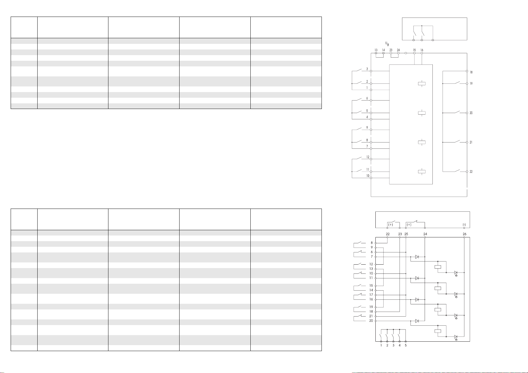
364 097
462 099 R
Klemme
Terminal
Borne
Morsetto
Belegung Assignment Affectation Assegnazione
13, 14, 23, 24 Betriebsspannung Operating voltage Tension de service Tensione di esercizio
1, 2, 3 Sensor 1 Sensor 1 Capteur 1 Sensore 1
4, 5, 6 Sensor 2 Sensor 2 Capteur 2 Sensore 2
7, 8, 9 Sensor 3 Sensor 3 Capteur 3 Sensore 3
10, 11, 12 Sensor 4 Sensor 4 Capteur 4 Sensore 4
15, 16 Schließer-Ausgang für Auswerteeinheit Contact maker output for control unit Sortie contact de travail pour unité de
contrôle Uscita contatto NO per unità di controllo
18 Gemeinsamer Anschluss für
Kontrollausgänge Common connection for control outputs Connexion commune pour sorties de
contrôle Collegamento comune per uscite di
controllo
19 Kontrollausgang 1 Control output 1 Sortie de contrôle 1 Uscita di controllo 1
20 Kontrollausgang 2 Control output 2 Sortie de contrôle 2 Uscita di controllo 2
21 Kontrollausgang 3 Control output 3 Sortie de contrôle 3 Uscita di controllo 3
22 Kontrollausgang 4 Control output 4 Sortie de contrôle 4 Uscita di controllo 4
Klemme
Terminal
Borne
Morsetto
Belegung Assignment Affectation Assegnazione
1Kontrollausgang, Sensor 1 Control output, sensor 1 Sortie de contrôle, capteur 1 Uscita di controllo, sensore 1
2 Kontrollausgang, Sensor 2 Control output, sensor 2 Sortie de contrôle, capteur 2 Uscita di controllo, sensore 2
3Kontrollausgang, Sensor 3 Control output, sensor 3 Sortie de contrôle, capteur 3 Uscita di controllo, sensore 3
4 Kontrollausgang, Sensor 4 Control output, sensor 4 Sortie de contrôle, capteur 4 Uscita di controllo, sensore 4
5Gemeinsamer Anschluss für
Kontrollausgänge Common connection for control outputs Connexion commune pour sorties de
contrôle Collegamento comune per uscite di
controllo
6, 7 Sensor 1, Öffnerkontakt Sensor 1, contact breaker Capteur 1, contact de repos Sensore 1, contatto NC
8, 9 Sensor 1, Schließerkontakt (wenn nicht
nötig: überbrücken) Sensor 1, contact maker (to be bridged, if
not needed) Capteur 1, contact de travail (si inutile :
ponter) Sensore 1, contatto NO (se non
necessario: cavallottare)
10, 11 Sensor 2, Öffnerkontakt Sensor 2, contact breaker Capteur 2, contact de repos Sensore 2, contatto NC
12, 13 Sensor 2, Schließerkontakt (wenn nicht
nötig: überbrücken) Sensor 2, contact maker (to be bridged, if
not needed) Capteur 2, contact de travail (si inutile :
ponter) Sensore 2, contatto NO (se non
necessario: cavallottare)
14, 15 Sensor 3, Schließerkontakt (wenn nicht
nötig: überbrücken) Sensor 3, contact maker (to be bridged, if
not needed) Capteur 3, contact de travail (si inutile :
ponter) Sensore 3, contatto NO (se non
necessario: cavallottare)
16, 17 Sensor 3, Öffnerkontakt Sensor 3, contact breaker Capteur 3, contact de repos Sensore 3, contatto NC
18, 19 Sensor 4, Schließerkontakt (wenn nicht
nötig: überbrücken) Sensor 4, contact maker (to be bridged, if
not needed) Capteur 4, contact de travail (si inutile :
ponter) Sensore 4, contatto NO (se non
necessario: cavallottare)
20, 21 Sensor 4, Öffnerkontakt Sensor 4, contact breaker Capteur 4, contact de repos Sensore 4, contatto NC
22, 23 Schließer-Ausgang für Auswerteeinheit Contact maker output for control unit Sortie contact de travail pour unité de
contrôle Uscita contatto NO per unità di controllo
24, 25 Öffner-Ausgang für Auswerteeinheit Contact breaker output for control unit Sortie contact de repos pour unité de
contrôle Uscita contatto NC per unità di controllo
26 Anschluss Gerätemasse Negative terminals Borne de mise à la terre de l’appareil Collegamento massa apparecchio
364 097
462 099 R
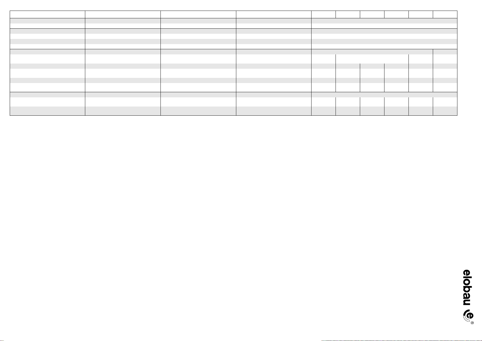
Technische Daten Technical data Caractéristiques techniques Specifiche tecniche 363 098 363 R98 363 V98 363 V99 364 097 462 099 R
Betriebstemperatur Operating temperature Température de service Temperatura di esercizio 0...+55°C
Transport- und Lagertemperatur Transport and storage temperature Température de transport et de stockage Temperatura di trasporto e di immagazzinaggio -25 ... +85 °C
Vibrations- und Stoßfestigkeit Vibration and shock resistance Résistance aux vibrations et aux chocs Resistenza alle vibrazione e agli urti
Schwingen Vibration Oscillations Oscillazioni 10 ... 55 Hz, 1 mm
Schocken Shock Chocs Urti 30 g / 11 ms
Dauerschocken Continuous shock Chocs continus Urti continui 10 g / 16 ms
Schutzart International protection Classe de protection Tipo di protezione IP 00 IP 20
Betriebsspannung Operating voltage Tension de service Tensione di esercizio 24 V DC 24 V DC ± 10 % 24 V AC/DC
±10% 24 V DC
Stromaufnahme Power consumption Consommation de courant Corrente assorbita 20 mA 30 mA - - 50 mA 40 mA
Maximale Schaltspannung Max. switching voltage Tension de commutation maximale Tensione di collegamento massima - - - - 30 V 250 V AC;
30 V DC
Maximaler Schaltstrom Max. switching current Courant de commutation maximal Corrente di commutazione massima ----1 A 1 A
Maximaler Ausgangsstrom
Kontrollausgänge 1...4 Maximum output current
control outputs 1...4 Courant de sortie maximal
sorties de contrôle 1...4 Corrente in uscita massima
uscite di controllo 1...4 10mA-----
Belastbarkeit Anzeige extern External stressability indicator Capacité de charge affichage externe Carico ammissibile indicatore esterno
Auswerteeinheit mit Betriebsspannung 24 V Control unit with 24 V operating voltage Unité de contrôle avec tension de service 24 V Unità di controllo con tensione di esercizio 24 V 100 mA /
2,4 W -----
Auswerteeinheit mit Betriebsspannung 230 V Control unit with 230 V operating voltage Unité de contrôle avec tension de service 230 V Unità di controllo con tensione di esercizio
230 V 10 mA /
0,24 W - - - - -
Art.-Nr./Art. No./Réf./N° art.: 900564 Version/Version/Version/Versione: 1.2 Datum/Date/Date/Data: 12.06.2008
Other manuals for 363 098
1
This manual suits for next models
5
Table of contents
Other elobau Control Unit manuals


