Power-Tronics PC300B User manual

© 2021 Power-Tronics, Inc.
The Power-Tronics PC300B Phase control
is a self-contained complete Phase control
designed for continuous operation at up to
210vdc at 30Adc!
The PC300B is uniquely designed to sit in
a compact footprint while being passively
convection cooled for a long service life.
Because of its unique modular design, the
PC300B minimizes downtime should a
repair ever be necessary! All serviceable
parts are easily removable without the
need to remove the chassis from the
mounting cabinet or tray. The compact
design allows a wide variety of installation
methods, including installations where
space is at a premium.
Over 30 years of field use and design
refinement makes the PC300B a time-
proven design, utilizing high-reliability
components, and a unique modular design
to simplify repair. The PC300B is
designed to provide a lifetime of service
and is specifically built to minimize failures
and potential downtime!
The PCMG-B control module includes an
internal 0-10VDC or 4-20mA interface
module to allow a wide variety of VAR, PF,
or other PLC controls to remotely control
the unit. An optional motorized
potentiometer allows remote operation by
dry contact switching or older pulsed-DC
control schemes.
The PC300B Phase control is the latest
upgrade to the PC300B series of phase
controls.
PC300B
Phase Control
Specifications
Input Voltage: 208 - 240vac
Frequency: 50 or 60 Hz
Voltage Regulation: +/- .25% From NL to FL
Output Voltage Range: 0-210vdc @ 240vac input
Maximum Forcing Output: 210vdc @ 30adc
Rated Continuous Output: 125vdc @ 25adc
Minimum Field Resistance: 7Ω @ 210vdc output
Min Residual Build up Voltage: 5vac
Under Frequency Protection: Yes, VPH reduction
Physical Size: 10 x 10 x 4 in.
Weight: 4 lb.
Integrated Control Module: PCMG-B
Repairable: Yes
Internal Protection: Fuses, cartridge type
External Voltage Adjustment: Yes
System Operating Indicator: Yes
Optional External Controls Yes
Integrated 0-10VDC / 4-20mA Interface: Yes

2
For Technical Support:
Visit our website at: www.power-tronics.com
Call Us at: (830) 895-4700
Table of Contents
Introduction and Functional Description:....................................................................3
Determining Application Sizing:...................................................................................4
Included Parts & Accessories:......................................................................................6
Mounting Dimensions & Chassis Ground:...................................................................7
Input Power & Field Connection Diagram:...................................................................8
PCMG-B Control Module:..............................................................................................9
Standard Control Wiring Diagram:..............................................................................10
Fully Automatic Remote Adjustment Wiring Diagram:.............................................11
Automatic / Manual Selectable Remote Adjustment Wiring Diagram:....................12
Initial Setup and Commissioning:...............................................................................13
Bench Check Procedures:...........................................................................................14
Installation Warranty Form:.........................................................................................15
Product Warranty Certificate:......................................................................................16

3
For Technical Support:
Visit our website at: www.power-tronics.com
Call Us at: (830) 895-4700
Introduction and Functional Description
Caution: Read This Installation
Manual Carefully and Entirely!
Warning: Do not use digital equipment to read voltage, Hz, or amperage
during this installation. Use only Analog sensing equipment! Failure to do so
may result in damage to equipment or in personal injury!
ALWAYS perform all setup procedures off-line
ALWAYS wear eye protection
ALWAYS strip wire insulation properly or use insulated connectors
ALWAYS use analog metering equipment when setting up the regulator
ALWAYS ensure the static exciter receives ample airflow
ALWAYS use adequate fusing
NEVER hold the static exciter in your hand or lap when energized
NEVER install the static exciter in a place it can be exposed to the elements or moisture
NEVER mount the static exciter over a screw, bolt, rivet, seam, or other fastener
NEVER remove the regulator cover while the unit is in operation
NEVER insert a screwdriver or other object under the regulator cover
NEVER touch any exposed part of the PC300B during operation
NEVER install a switch in the DC portion of the static exciter’s wiring
NEVER USE A DIGITAL FREQUENCY METER (It can give a false reading!)
Functional Description
The PC300B Phase Control is the result of over 30 years of engineering efforts and offers high-
demand features at a competitive price point. The PC300B is a proven design and is engineered
to greatly simplify setup while offering extreme reliability. When properly installed, the PC300B
Phase Control is designed to provide a lifetime of service.
An automatic phase control has several automated tasks it must perform in order to provide
reliable, clean, and regulated electricity. It must maintain a preset setpoint and protect both itself
and the connected load should a fault situation arise.
The PC300B uses field-replaceable cartridge fuses to protect its internal circuitry should a fault
occur and the load current exceeds what the phase control is capable of delivering. It also
contains reliable circuitry that is designed to maintain a setpoint regardless of outside influences
or ambient temperature.
Due to its extreme simplicity, the PC300B Phase Control is uncommonly reliable and offers
features and accuracy usually only offered by much more complicated and often much more
expensive phase controls.

4
For Technical Support:
Visit our website at: www.power-tronics.com
Call Us at: (830) 895-4700
Determining Correct Application Sizing
The PC300B Phase control is designed for use with 120-240VAC input. It contains internal
suppression for use with brush-type loads such as synchronous motors. Before installation, it is
necessary to verify that the PC300B is the correct product for your application.
To determine if the PC300B is the correct product for your load you need to know any two of the
following 3 specifications from the rating plate of your load:
1: Control Field Voltage (in DC Volts) [Generally given in full load Voltage on nameplates]
2: Control Field Resistance (in Ohms) [See Note Below]
3: Connected Load Amperage (in DC Amps) [Generally given in full load Amps on nameplates]
Using the specifications obtained from your connected load, verify
that your load fits the specifications below:
• Connected load full load voltage is 100VDC or less, and your control field
resistance is 3.5Ω or greater. Use 120VAC Input Voltage.
• Connected load full load voltage is 200VDC or less, and your control field
resistance is 7Ω or greater. Use 240VAC Input Voltage.
WARNING: BRUSH AND SLIP RING CONNECTION PROBLEMS ARE
THE #1 SOURCE OF VOLTAGE CONTROL PROBLEMS AND FAILURE OF PHASE
CONTROLS!!! DO NOT INSTALL THE PC300B IF THE BRUSHES AND/OR SLIP
RINGS ARE NOT IN EXCELLENT CONDITION!!!
STOP AND CORRECT BRUSH AND SLIP RING CONNECTION PROBLEMS IF ANY
OF THE FOLLOWING CONDITIONS ARE PRESENT:
• GROOVES IN SLIP RINGS
• ROUGH SLIP RING APPEARANCE OR GHOSTING (CHATTERING)
• OIL CONTAMINATION ON BRUSHES OR SLIP RINGS
• DULL, ROUGH, STRIPED, PITTED, OR METALLIC APPEARANCE OF BRUSH
FACES
• FIELD RESISTANCE MEASURED BETWEEN SLIP RING BRASS AND FIELD
RESISTANCE MEASURED BETWEEN FIELD LEADS EXCEEDS 1-2% DIFFERENCE

5
For Technical Support:
Visit our website at: www.power-tronics.com
Call Us at: (830) 895-4700
Note about Field Resistance
When measuring field resistance on a brush-type device, such as
a synchronous motor, measure the resistance through both the
field leads as well as directly on the slip rings themselves.
The readings you obtain should ideally be the same, but no
more than 1% difference.
If you show more than 1% difference in reading your device has
brush and ring contact problems and will need cleaning or
maintenance before installing the PC300B.
Failure to correct brush and ring contact problems will
result in severe damage to the phase control as well
as possible PERMANENT damage to the slip rings
themselves!
NEVER use emery cloth, carborundum stones, “comm
sticks”, or Tuner cleaner to dress or clean slip rings!
They will make a bad problem much, much worse! Only use
Garnet or Flint sandpaper and clean with a clean rag soaked with
Acetone for best results!
6
For Technical Support:
Visit our website at: www.power-tronics.com
Call Us at: (830) 895-4700
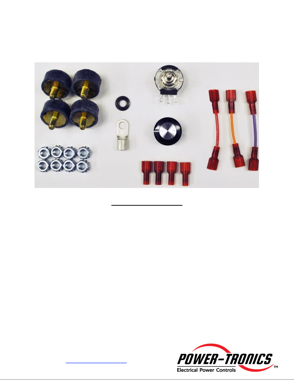
Included Parts & Accessories
The PC300B Static Exciter includes the following parts and
accessories to ensure a quick and easy installation:
Included Parts List:
• Vibration Isolators Qty: 4
• ¼-20 Self-Locking Nuts Qty: 8
• #16-14AWG Compression Terminal Qty: 1
• ¼” Bellville Washer Qty: 1
• 100K 2W Long-Life Potentiometer Qty: 1
• Panel Knob for Potentiometer Qty: 1
• #22-18AWG .250 Female Terminals Qty: 4
• Red Jumper Wire Qty: 1
• Orange Jumper Wire Qty: 1
• Purple Jumper Wire Qty: 1

7
For Technical Support:
Visit our website at: www.power-tronics.com
Call Us at: (830) 895-4700
Mounting Dimensions & Chassis Ground
Chassis Should Be
Grounded
For Safety!!!
Use Supplied Compression Terminal
And Bellville Washer Provided In
Accessories Kit
Attach to Bottom Right Mounting Point.
Torque to 125 in•lbf (15N•M)
PCMG-B

8
For Technical Support:
Visit our website at: www.power-tronics.com
Call Us at: (830) 895-4700
Input Power & Field Connection Diagram
(See page 10 for control wiring information)
WARNING: The PC300B Phase Control is NOT
Suitable for use on Electrical Generators Without a
Suitable Voltage Control Source!!!
The PC300B is a Full-Wave rectified phase control, which allows a maximum of 210VDC
@ 240VAC or 105VDC @120VAC at 30 ADC continuous.
This product is typically used on slip-ring synchronous motors or on inductive loads with
full load control field voltages of 125VDC or less and full load exciter field amperage
between 5 and 30ADC. Control fields with lower voltages can use the PC300B with
a 120VAC input voltage for a maximum output of 105VDC @ 30ADC.
Note that the maximum input voltage to the PC300B Phase control is 240VAC! DO
NOT input 277VAC into the PC300B! Severe damage to the unit will result! For use
on 480V or higher systems, connect the PC300B to an appropriate step-down
transformer to supply 240VAC to the PC300B.
Diagram Assumes a 208-240V
Input Voltage
For 480V Systems, use a 10KVA
(or larger) Transformer with a 240V
NOTE:
Diagram shows an isolation
transformer, which is
recommended for ALL
installations. An isolation
transformer will save your
bearings should the rotor ever
short to ground!
NEVER install a switch or
breaker on the DC or
Exciter side of the phase
control!
Only install a switch or
disconnect on the AC
Side of the phase control!
10KVA or Greater
240V Secondary
See Pages 10-12
for Control Wiring
Diagrams
Torque All Terminal
Connections to
125 in•lbf (15 N•M)
120-240VAC
From Power
Supply
Main Disconnect

9
For Technical Support:
Visit our website at: www.power-tronics.com
Call Us at: (830) 895-4700
PCMG-B Control Module
The PCMG-B Control Module is an integrated device designed to replace multiple discrete
components in previous generations of Phase Controls. It incorporates a Phase Control
Module, AC Input Filtering, and integrated 0-10VDC / 4-20mA Interface Module.
The unitary design simplifies installation in the field, and greatly simplifies replacement if a fault
occurs with the control module. The unit has 5 color-coded wires with quick-connect terminals,
and can be quickly swapped out in less than 5 minutes without the need to remove the chassis
from its enclosure or tray.
Power
Status
Lamp
V/MA Jumper
Terminal Descriptions:
Colored Terminals:
Chassis Wiring (Color-Coded)
G1 & G2:
Gate Enable Pins
Short G1 & G2 To Operate
Switch or Relay Recommended
If No Switch, Install Red Jumper
R1 & R2:
Remote Adjustment Input
U- & U+:
Output From Internal Analog
Input Module
CV- & CV+:
Input for 0-10V or 4-20mA Signal
V/MA Jumper:
Installed for 4-20ma Signal
Remove for 0-10V Signal
Base Voltage
Trim Control
25 Turn Pot!

10
For Technical Support:
Visit our website at: www.power-tronics.com
Call Us at: (830) 895-4700
Standard Control Wiring Diagram
This wiring diagram shows the default control wiring configuration for the PC300B and
assumes manual control with a remote potentiometer. Power wiring is shown on
Page 8.
NOTE:
It is not necessary
to jumper terminals
R1 and R2 if not
using the Remote
Voltage Adjustment!
NOTE:
If not using a switch,
Install Red Jumper
from Accessory Kit
100KΩ @ 2w
Table of contents
Other Power-Tronics Control Unit manuals


Popular Control Unit manuals by other brands

Festo
Festo Compact Performance CP-FB6-E Brief description

Elo TouchSystems
Elo TouchSystems DMS-SA19P-EXTME Quick installation guide

JS Automation
JS Automation MPC3034A user manual

JAUDT
JAUDT SW GII 6406 Series Translation of the original operating instructions

Spektrum
Spektrum Air Module System manual

BOC Edwards
BOC Edwards Q Series instruction manual

KHADAS
KHADAS BT Magic quick start

Etherma
Etherma eNEXHO-IL Assembly and operating instructions

PMFoundations
PMFoundations Attenuverter Assembly guide

GEA
GEA VARIVENT Operating instruction

Walther Systemtechnik
Walther Systemtechnik VMS-05 Assembly instructions

Altronix
Altronix LINQ8PD Installation and programming manual


