elobau eloProg User manual
Type no.: 350HB002 Version: 1.3 Date: 13.04.2016
eloProg
Configurable safety system
Manual (translation of the original manual)

Type no.: 350HB002 Version: 1.3 Date: 13.04.2016
TABLE OF CONTENTS
1 INTRODUCTION .................................................................................................. 1-1
1.1 Contents of this handbook ................................................................................................ 1-1
1.2 Important safety instructions ............................................................................................. 1-1
1.3 Abbreviations and symbols .............................................................................................. 1-2
1.4 Applicable standards......................................................................................................... 1-2
2 OVERVIEW .......................................................................................................... 2-1
3 SCOPE OF SUPPLY............................................................................................ 3-1
4 INSTALLATION ................................................................................................... 4-1
4.1 Mechanical fastening ........................................................................................................ 4-1
4.2 Calculation of safety distance of an electro-sensitive protective system connected
to eloProg.......................................................................................................................... 4-2
4.3 Electrical connections ....................................................................................................... 4-2
4.3.1 Instructions concerning connection cables ...................................................................... 4-3
4.3.2 USB input.......................................................................................................................... 4-4
4.3.3 eloProg memory stick (350EPS)....................................................................................... 4-4
Function MULTIPLE LOAD............................................................................................... 4-5
RESTORE function ........................................................................................................... 4-5
4.3.4 Encoder connections with RJ45 connector (485EPS1, 485EPS2) ................................. 4-11
4.3.5 Example for connecting the eloProg system to the machine controller .......................... 4-13
4.4 Checklist after installation ............................................................................................... 4-13
5 FUNCTIONAL DIAGRAM .................................................................................... 5-1
6 DESCRIPTION OF SIGNALS .............................................................................. 6-1
6.1 Inputs ................................................................................................................................ 6-1
6.1.1 MASTER ENABLE............................................................................................................ 6-1
6.1.2 NODE SEL........................................................................................................................ 6-1
6.1.3 Initiator input proximity for 485EPS2N .............................................................................. 6-2
Configuration with overlapping initiator signals................................................................. 6-2
6.1.4 RESTART_FBK ................................................................................................................ 6-3
6.2 Outputs ............................................................................................................................. 6-4
6.2.1 OUT STATUS ................................................................................................................... 6-4
6.2.2 OUT TEST ........................................................................................................................ 6-4
6.2.3 OSSD (Module 485EPB, 485EPE08A02, 485EPA02, 485EPA04) .................................. 6-4
6.2.4 Relay modules (485EPR02, 485EPR04).......................................................................... 6-5
Characteristics of the output circuit................................................................................... 6-5
Module 485EPR02/485EPR04 internal contacts .............................................................. 6-6
Wiring example of the relay module 485EPR02 to the basic module 485EPB................. 6-7
Functional diagram of output circuit connected to the module 485EPR02 / 485EPR04... 6-7
7 TECHNICAL SPECIFICATIONS.......................................................................... 7-1
7.1 General system characteristics......................................................................................... 7-1
7.1.1 Safety parameters of the system ...................................................................................... 7-1
7.1.2 General data ..................................................................................................................... 7-1
7.1.3 Housing............................................................................................................................. 7-2
7.1.4 Basic module 485EPB ...................................................................................................... 7-2
7.1.5 I/O module 485EPE08A02................................................................................................ 7-2
7.1.6 Input modules 485EPE08 - 485EPE12 - 485EPE16 ........................................................ 7-3
7.1.7 Output modules 485EPA02 - 485EPA04 .......................................................................... 7-3
7.1.8 Output modules 485EPR02 - 485EPR04.......................................................................... 7-3
7.1.9 Speed monitoring modules 485EPS2N - 485EPS1 - 485EPS2........................................ 7-4
7.1.10 Modules 485EPR04S00B - 485EPR04S08B.................................................................... 7-5
7.2 Mechanical dimensions..................................................................................................... 7-5

Type no.: 350HB002 Version: 1.3 Date: 13.04.2016
7.3 Signals .............................................................................................................................. 7-7
7.3.1 Basic module 485EPB ...................................................................................................... 7-7
7.3.2 I/O module 485EPE08A02................................................................................................ 7-9
7.3.3 Input module 485EPE08 ................................................................................................. 7-10
7.3.4 Input module 485EPE12 ................................................................................................. 7-11
7.3.5 Input module 485EPE16 ................................................................................................. 7-12
7.3.6 Output module 485EPA02 .............................................................................................. 7-13
7.3.7 Output module 485EPA04 .............................................................................................. 7-14
7.3.8 Module 485EPR04S00B ................................................................................................. 7-15
7.3.9 Module 485EPR04S08B ................................................................................................. 7-16
7.3.10 Modules 485EPS2N, 485EPS1, 485EPS2 ..................................................................... 7-17
7.3.11 Relay output modules 485EPR02/485EPR04 ................................................................ 7-18
7.4 Fault diagnosis................................................................................................................ 7-19
7.4.1 Basic module 485EPB .................................................................................................... 7-19
7.4.2 I/O module 485EPE08A02.............................................................................................. 7-20
7.4.3 Input module 485EPE08 ................................................................................................. 7-21
7.4.4 Input module 485EPE12 ................................................................................................. 7-22
7.4.5 Input module 485EPE16 ................................................................................................. 7-23
7.4.6 Output module 485EPA02/485EPA04 ............................................................................ 7-24
7.4.7 Module 485EPR04S00B ................................................................................................. 7-25
7.4.8 Module 485EPR04S08B ................................................................................................. 7-26
7.4.9 Modules 485EPS2N, 485EPS1, 485EPS2 ..................................................................... 7-27
8 CONFIGURATION SOFTWARE.......................................................................... 8-1
8.1 Installing the software ....................................................................................................... 8-1
8.1.1 PC hardware requirements ............................................................................................... 8-1
8.1.2 PC software requirements ................................................................................................ 8-1
8.1.3 How to install the configuration software .......................................................................... 8-1
8.1.4 Fundamentals ................................................................................................................... 8-2
8.1.5 Standard toolbar ............................................................................................................... 8-3
8.1.6 Textual toolbar .................................................................................................................. 8-4
8.1.7 Create a new project......................................................................................................... 8-4
8.1.8 Edit configuration (composition of the various modules) .................................................. 8-5
8.1.9 Change user parameters ................................................................................................. 8-5
8.1.10 Toolbar buttons - Operators - Configuration ..................................................................... 8-6
8.1.11 Creating the diagram (configuration) ................................................................................ 8-7
8.1.12 Example of a project ......................................................................................................... 8-8
Project validation .............................................................................................................. 8-8
Project report .................................................................................................................... 8-9
Connect to eloProg ........................................................................................................ 8-10
Send configuration to eloProg ........................................................................................ 8-10
Download a configuration file (project) from the basic module 485EPB ........................ 8-10
Configuration LOG ....................................................................................................... 8-11
System structure ............................................................................................................ 8-11
Disconnecting the system ............................................................................................. 8-12
MONITOR (status of I/O in real time - text) ................................................................... 8-12
MONITOR (status of I/O in real time - graphical) .......................................................... 8-13
8.1.13 Password protection ....................................................................................................... 8-14
Level 1 password ............................................................................................................ 8-14
Level 2 password ............................................................................................................ 8-14
Password change ......................................................................................................... 8-15
8.1.14 System Test ................................................................................................................... 8-16

Type no.: 350HB002 Version: 1.3 Date: 13.04.2016
8.2 Function blocks ............................................................................................................... 8-17
8.2.1 OUTPUTS....................................................................................................................... 8-17
OSSD (semiconductor safety outputs)............................................................................ 8-17
Status output................................................................................................................... 8-17
FIELDBUS PROBE (fieldbus sensor) ............................................................................. 8-18
RELAY ............................................................................................................................ 8-19
8.2.2 INPUTS........................................................................................................................... 8-21
E-STOP (emergency stop, one and two-channel) .......................................................... 8-21
E-GATE (mobile separating guard, two-channel) ........................................................... 8-23
SINGLE E-GATE (mobile separating guard, one-channel)............................................. 8-25
LOCK FEEDBACK (lock monitoring) .............................................................................. 8-26
ENABLE (key switch)...................................................................................................... 8-27
ESPE (Electro sensitive protective system: safety light barrier / laser scanner)............. 8-29
FOOTSWITCH (safety pedal / foot switch) ..................................................................... 8-30
MOD-SEL (mode selection switch)................................................................................. 8-32
PHOTOCELL (Safety light barrier).................................................................................. 8-33
TWO-HAND (two hand control) ...................................................................................... 8-34
SENSOR (photocell, initiator) ......................................................................................... 8-35
S-MAT (safety mat)......................................................................................................... 8-36
SWITCH.......................................................................................................................... 8-37
ENABLING GRIP SWITCH (enabling switch)................................................................. 8-38
TESTABLE SAFETY DEVICE (mechanical safety switch) ............................................. 8-40
SOLID STATE DEVICE (safety sensor with semiconductor outputs)............................. 8-42
FIELDBUS INPUT (fieldbus inputs) ................................................................................ 8-43
LL0-LL1........................................................................................................................... 8-43
COMMENTS ................................................................................................................... 8-43
TITLE .............................................................................................................................. 8-43
8.3 Function blocks of type SPEED MONITORING.............................................................. 8-44
SPEED CONTROL ......................................................................................................... 8-44
WINDOW SPEED CONTROL (speed control in measuring window)............................. 8-47
STILL STAND (stillstand check) ..................................................................................... 8-50
STAND STILL AND SPEED CONTROL (speed and standstill control).......................... 8-53
8.3.1 GUARD LOCK block....................................................................................................... 8-57
GUARD LOCK: Safety guard lock .................................................................................. 8-57
8.4 Operators (processing blocks) ........................................................................................ 8-59
8.4.1 Logic blocks .................................................................................................................... 8-59
AND: And block............................................................................................................... 8-59
NAND (NOT-AND): AND block with an inverted output.................................................. 8-59
NOT: Inverter block......................................................................................................... 8-60
OR: OR block.................................................................................................................. 8-60
NOR (NOT OR): OR block with an inverted output......................................................... 8-60
XOR (EXCLUSIVE OR): Exclusive OR block ................................................................. 8-61
XNOR (EXCLUSIVE NOT OR): Equivalent block........................................................... 8-61
MULTIPLEXER: Selection switch ................................................................................... 8-62
8.4.2 Memory blocks................................................................................................................ 8-63
D FLIP FLOP: Data flip flop edge-controlled................................................................... 8-63
SR FLIP FLOP: Set-Reset-Flipflop ................................................................................. 8-63
USER RESTART MANUAL: Restart inhibit, reset with rising edge ................................ 8-64
USER RESTART MONITORED: Restart inhibit, Start with falling edge......................... 8-64
8.4.3 Counter blocks ................................................................................................................ 8-65
COUNTER: Counter, up and down................................................................................. 8-65
8.4.4 TIMER operators............................................................................................................. 8-67
CLOCKING: Clock generator, controllable ..................................................................... 8-67
MONOSTABLE: Monoflop .............................................................................................. 8-68
PASSING MAKE CONTACT: Maximum time (pulse time limiter)................................... 8-69
DELAY: ON / OFF delay................................................................................................. 8-70

Type no.: 350HB002 Version: 1.3 Date: 13.04.2016
8.4.5 Muting ............................................................................................................................. 8-72
8.4.6 MUTING blocks............................................................................................................... 8-72
MUTING "Con" (Concurrent): 4-Sensor-Muting (double parallel) ................................... 8-72
MUTING "L" (L-arrangement): 2 Sensor single-side muting (parallel)............................ 8-74
MUTING "Seq" (Sequential): 4-sensor muting (serial).................................................... 8-75
MUTING "T" (T-arrangement): 2 Sensor two-sided muting (parallel) ............................. 8-77
MUTING OVERRIDE ...................................................................................................... 8-78
8.5 Various function blocks................................................................................................... 8-80
SERIAL OUTPUT: Serial transmission of status signals ................................................ 8-80
NETWORK...................................................................................................................... 8-81
INTERPAGE IN/OUT ...................................................................................................... 8-84
8.5.1 Special applications ........................................................................................................ 8-85
Output delay with manual operation ............................................................................... 8-85
8.5.2 EloProg error codes ........................................................................................................ 8-86
9 ACCESSORIES AND SPARE PARTS ................................................................ 9-1
10 EU-DECLARATION OF CONFORMITY ............................................................ 10-1

Type no.: 350HB002 Version: 1.3 Date: 13.04.2016 1-1
1 INTRODUCTION
1.1 Contents of this handbook
This handbook describes how to use the eloProg programmable safety module and its expansion
units (termed “SLAVES”) and
includes the following:
a description of the system
installation methods
connections
signals
diagnostics
use of the configuration software
1.2 Important safety instructions
Warning
This symbol designates an important instruction relating to personal safety. Failure to
comply can lead to a very high risk for the personnel concerned.
Note
This symbol indicates an important note.
Warning
eloProg fulfills the following safety levels: SIL 3, SILCL 3, PLe and Cat. 4, according to
applicable regulations.
However, the definitive SIL and PL of the application will depend on the number of
safety components, their parameters and the connections that are made, as per the risk
analysis.
Please read Sec. 1.4 Applicable standards on page 1-2 carefully.
Perform an in-depth risk analysis to determine the appropriate safety level for your spe-
cific application, on the basis of all the applicable standards.
Programming/configuration of the eloProg is the sole responsibility of the installer or
user.
The device must be programmed/configured in accordance with the application-specific
risk analysis and all applicable standards.
Once you have programmed/configured and installed the eloProg and all the relative
devices, run a complete application safety test (see Sec. 8.1.14 System Test on
page 8-16).
elobau is not liable for these operations or any risks in connection therewith.
Refer to the operating manual and possibly the relevant product and/or equipment reg-
ulations to endure correct use of the devices connected to eloProg.
The customer must ensure full control of the system when new safety components are
added to the system itself (see Sec. 8.1.14 System Test on page 8-16).
The ambient temperature in the place where the system is installed must be compatible
with the operating temperature parameters stated on the product label and in the spec-
ifications.
For all matters concerning safety, if necessary, contact your country's competent safety
authorities or the competent trade association.

Type no.: 350HB002 Version: 1.3 Date: 13.04.2016 1-2
1.3 Abbreviations and symbols
1.4 Applicable standards
eloProg complies with the following European Directives:
2006/42/EC “Machinery Directive”
2004/108/EC “Electromagnetic Compatibility Directive”
2006/95/EC “Low-voltage Directive”
The following standards are complied with:
Tab. 1-1 Applicable standards
350EPS = eloProg memory stick for basic module 485EPB (accessory)
350EPT = eloProg T-distributor
350EPKS = eloProg configuration software
OSSD = Output Signal Switching Device: solid state safety output (safety output)
DC = Diagnostic Coverage: level of diagnostic coverage
MTTFd=Mean Time to Dangerous Failure
PL = Performance Level
PFHd=Probability of a dangerous failure per Hour
SIL = Safety Integrity Level
SILCL = Safety Integrity Level Claim Limit
SW = Software
CEI EN 61131-2
(2007)
Programmable controllers, part 2:
Equipment characteristics and tests
ISO 13489-1
(2008)
Safety of machinery:
Safety related parts of control systems. General principles for design
EN 61496-1
(2013)
Safety of machinery: Electro-sensitive protective systems, Part 1:
General requirements and tests
IEC 61508-1
(2010)
Functional safety of electrical/electronic/programmable electronic safety-related systems:
General requirements
IEC 61508-2
(2010)
Functional safety of electrical/electronic/programmable electronic safety-related systems:
Requirements for electrical/electronic/programmable electronic safety-related systems
IEC 61508-3
(2010)
Functional safety of electrical/electronic/programmable electronic safety-related systems:
Software requirements.
IEC 61784-3
(2008)
Digital data communication for measurement and control: Functional safety field buses
IEC 62061
(2013)
Safety of machinery: Functional safety of safety-related electrical, electronic and programmable electronic
control systems

Type no.: 350HB002 Version: 1.3 Date: 13.04.2016 2-1
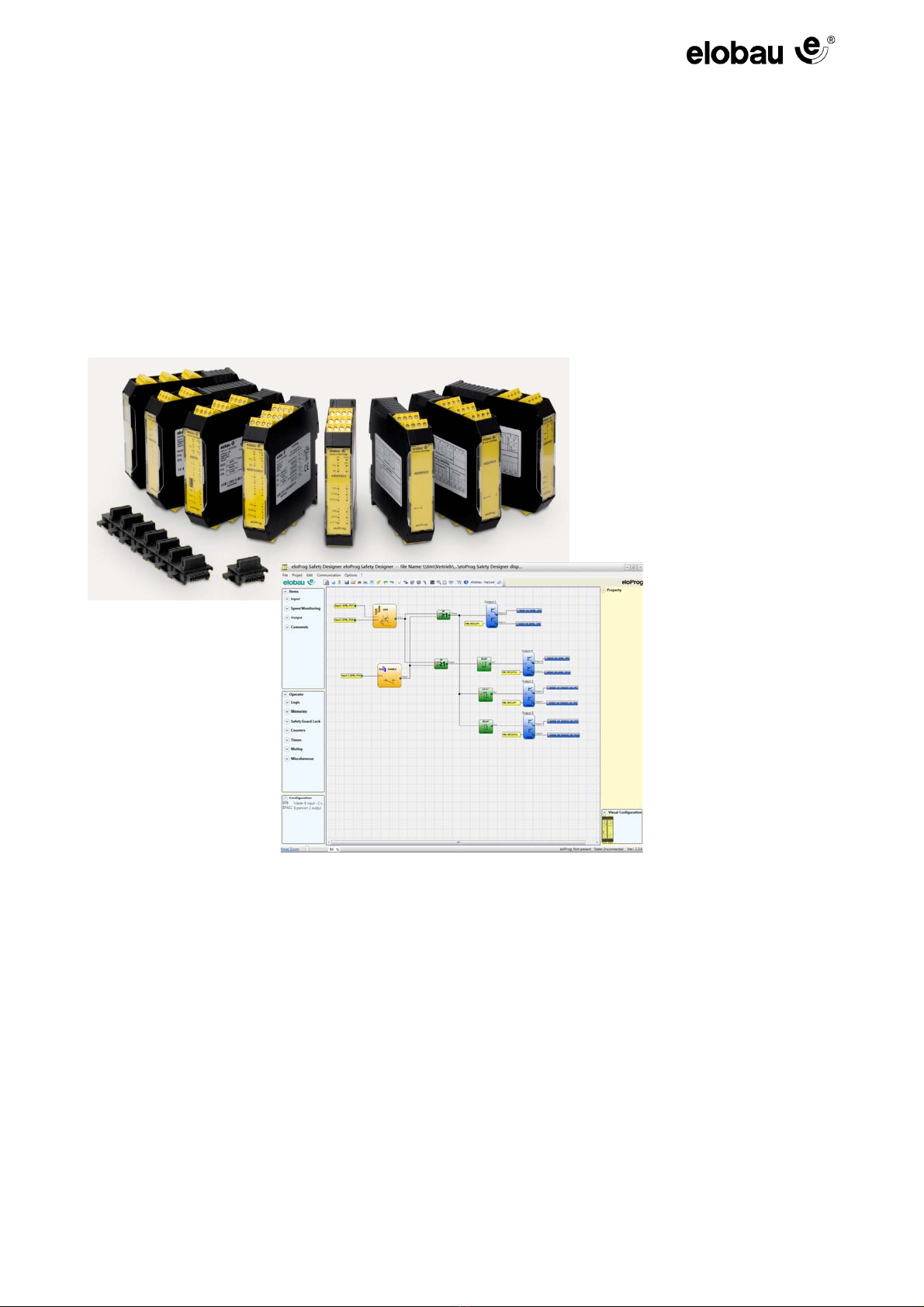
2OVERVIEW
eloProg is a modular safety controller consisting of a master unit (485EPB) and a number of expan-
sion units connected via the proprietary bus.
The master unit can be configured by means of a graphical user interface and has 8 safety inputs
and 2 independent programmable two-channel safety outputs. The master module can also be op-
erated independently (stand-alone).
The following sensors can be connected to eloProg:
optoelectronic sensors (safety light curtains, laser scanners, etc.), mechanical switches, emergency
stops, safety shut-off mats, two-hand controls, enabling switches, proximity switches.
The system must consist of just one master (Master Module 485EPB) and a maximum of 14 electronic
expansion modules, but not more than 4 of the same type.
With 14 expansions, the system can have up to 128 inputs, 16 two-channel safety outputs and
16 status outputs. The MASTER and its SLAVE units communicate via the 5-way bus sensor, phys-
ically arranged on the rear panel of each unit.
Furthermore 8 inputs and 16 outputs are available in association with the field bus modules. They
enable bidirectional controlling and reporting.
The expansion modules of the eloProg system 485EPE08, 485EPE16 and 485EPE12 allow the
number of inputs in the system to be increased and allow more external devices to be connected.
The 485EPE12 also provides 8 OUT_TEST outputs.
The expansion units of the eloProg system 485EPA02, 485EPA04 provide the system, respectively,
with 2 and 4 static OSSD safety outputs for controlling devices connected downstream of the eloProg.
The 485EPE08A02 has 8 inputs and 4 OSSD safety outputs.
The eloProg system expansion units 485EPR02 and 485EPR04provide the system with 2 and 4 NO
guided contact safety relay outputs, respectively, with the related external relay feedback (NC con-
tact).
The expansion units in the 485EPF series permit connection to the most commonly used industrial
fieldbus systems for diagnostics and data transmission. The 485EPFEI, 485EPFPN and 485EPFEC
also have an Ethernet connection.
The 485EPFUB permits connection to devices with a USB port.
Note
The following is available:
Input / output expansions:
(485EPE08A02)
Input expansions:
(485EPE08, 485EPE12, 485EPE16, 485EPS2N, 485EPS1x and 485EPS2x)
Output expansions:
(485EPA02 and 485EPA04)
Output modules with safety relays and forcibly guided contacts:
(485EPR02 and 485EPR04, 485EPR04S00B and 485EPR04S08B)
Fieldbus module:
485EPFPD (PROFIBUS DP), 485EPFCO (CanOpen), 485EPFDN (DeviceNet),
485EPFEI (Ethernet IP), 485EPFEI2 (Ethernet IP 2-way), 485EPFMR (Modbus RTU),
485EPFMT (Modbus TCP), 485EPFPN (Profinet), 485EPFPN2 (Profinet 2-way),
485EPFEC (EtherCat), 485EPFUB (USB interface module)
Bus transfer modules:
485EPT1, 485EPT2

Type no.: 350HB002 Version: 1.3 Date: 13.04.2016 2-2
The bus transfer modules 485EPT1, 485EPT2 enable the connection of 485EPB with other slave
modules, decentralized, at a distance of max. 50 m. By using a shielded cable, the bus transfer mod-
ules are connected at the desired distance.
The following functions can be monitored with the speed monitoring modules 485EPS2N,
485EPS1x, 485EPS2x:
standstill, maximum speed, speed range;
direction of rotation
There can be up to 4 switching points freely configured for speed limitation for each input (axis).
Each unit incorporates two configurable outputs and is thus capable of controlling up to 2 indepen-
dent axes.
The 485EPR04S00B and 485EPR04S08B relay modules are provided with 4 independent safety re-
lay outputs and the corresponding 4 inputs for the external feedback contacts (EDM).
2 settings are possible (configuration via elobau Safety Designer) for the outputs:
2 double connection contacts (2 NO contacts per output with 2 corresponding feedback inputs).
4 independent single connection contacts (1 NO contact per output with 1 corresponding feedback
input).
Only the 485EPR04S08B unit has 8 programmable signal outputs.
The eloProg configuration software is capable of creating complex logics, by using logical operators
and safety functions such as muting, timer, counters, etc.
All this is performed by means of an easy and intuitive graphical user interface.
The configuration performed on the PC is sent to the 485EPB module via USB connection. The file
is stored on the 485EPB and can also be stored on the proprietary Memory Stick 350EPS (accesso-
ry). Thus, a quick transfer of the configuration to other 485EPB modules is easily possible.
Note
The eloProg system is certified to the maximum safety level envisaged by the applicable
industrial safety standards (SIL 3, SILCL 3, PL e and Cat. 4).

Type no.: 350HB002 Version: 1.3 Date: 13.04.2016 3-1
3 SCOPE OF SUPPLY
The basic module 485EPB is supplied with:
– CD-ROM containing the free configuration software and PDF manual
The expansion units are supplied with:
– Rear bus (T-distributor 350EPT),
(not included with relay output modules 485EPR02 and 485EPR04 because they are connected
only via the terminals).
Note
The rear panel connector (T-distributor 350EPT) and the memory stick (350EPS) can be
ordered separately as accessories.
Note
To install an expansion unit (excluding relays) you will need the T-distributor supplied with
the unit plus another bus connector (T-distributor) for the connection to the 485EPB basic
module. This can be ordered separately as an accessory.

Type no.: 350HB002 Version: 1.3 Date: 13.04.2016 4-1
4INSTALLATION
4.1 Mechanical fastening
The modules are mounted on a 35 mm DIN rail (EN 5022) as follows:
1. Plug the number of T-distributors together corresponding to the number of modules to be assem-
bled.
2. Fasten the assembled T-distributors (top first) to the 35 mm DIN rail (EN 5022).
3. Then attach the modules on the rail and put the contact device at the bottom of the module on the
corresponding T-distributor. Carefully press the module in until it locks into place.
4. To remove a unit, use a screwdriver to pull down the locking latch on the back of the unit; then lift
the unit upwards and pull.
Fig. 4-1 Mechanical fastening
1. 2.
3. 4.

Type no.: 350HB002 Version: 1.3 Date: 13.04.2016 4-2
4.2 Calculation of safety distance of an electro-sensitive protective system con-
nected to eloProg
Any electro-sensitive protective system (ESPE) connected to eloProg must be positioned at a dis-
tance equal to or greater than the minimum safety distance S so that the dangerous point can be
reached only after stopping the dangerous movement of the machine.
* “Describes the methods which can be used by the designer for calculating minimum safety distances from hazards for
specific safety devices, especially for electro-sensitive protective systems (for example, photocells), pressure-sensitive
mats or treads and two-hand controls. Contains a rule for determining the arrangement of the safety devices based on
approach speed and the holding time of the machine, which can be reasonably extrapolated so that the locked doors
are included, without locking the guard.”
4.3 Electrical connections
Fig. 4-2 Electrical connections
Warning
European standard: ISO 13855:2010- (EN 999:2008) Safety of machinery. The positioning
of protective equipment in respect of approach speeds of parts of the body* contains
formulas for calculating the correct safety distances.
Note also the installation manual of each device to receive specific information
regarding the arrangement.
It should be noted that the total response time of the system depends on the following
factors:
Reaction time eloProg + response time ESPE + reaction time machine (the reaction
time of the machine from the from the moment at which the stop signal is transmitted
until the time needed to stop dangerous movements).
The modules are equipped with terminals for the electrical con-
nections. Each module has 8, 16 or 24 terminals.
Each module also has a rear port (for communication with the
master and the other expansion modules).
485EPR02 and 485EPR04 are only connected via the terminals.
Terminal torque: 0.6 - 0.7 Nm
Warning
Install the safety units in an enclosure with a protection class of at least IP54.
Connect the module when it is not powered.
The supply voltage to the units must be 24 VDC ±20 % (PELV, in compliance with the
Standard EN 60204-1 (chapter 6.4)).
Do not use the eloProg to supply external devices.
The same ground connection (0 VDC) must be used for all system components.

Type no.: 350HB002 Version: 1.3 Date: 13.04.2016 4-3
4.3.1 Instructions concerning connection cables
The following details the terminals for each individual module:
Tab. 4-1 Connections - master module 485EPB
Note
Wire size range: AWG 12 ÷ 30, (solid/stranded) (UL).
Use copper (Cu) with 60 °C/75 °C conductors only.
We recommend the use of separate power supplies for the safety module and for other
electrical power equipment (electric motors, inverters, frequency converters) or other
sources of disturbance.
Cables used for connections of longer than 50 m must have a cross-section of at least
1mm
2 .
Basic module (Master) 485EPB
TERMINAL SIGNAL TYPE DESCRIPTION OPERATION
124VDC - 24 VDC supply -
2 MASTER_ENABLE1 Input MASTER_ENABLE Input ("Type B" according to EN 61131-2)
3 MASTER_ENABLE2 Input Input ("Type B" according to EN 61131-2)
4GND - Supply 0 VDC -
5 OSSD1_A Output Safety output 1 PNP active
6 OSSD1_B Output PNP active
7 RESTART_FBK1 Input Feedback loop / Restart 1 Input according to EN 61131-2
8OUT_STATUS1 Output Status output 1 PNP active
9 OSSD2_A Output Safety output 2 PNP active
10 OSSD2_B Output PNP active
11 RESTART_FBK2 Input Feedback loop / Restart 2 Input according to EN 61131-2
12 OUT_STATUS2 Output Status output 2 PNP active
13 OUT_TEST1 Output Short circuit detected output PNP active
14 OUT_TEST2 Output Short circuit detected output PNP active
15 OUT_TEST3 Output Short circuit detected output PNP active
16 OUT_TEST4 Output Short circuit detected output PNP active
17 INPUT1 Input Safety digital input 1 Input according to EN 61131-2
18 INPUT2 Input Safety digital input 2 Input according to EN 61131-2
19 INPUT3 Input Safety digital input 3 Input according to EN 61131-2
20 INPUT4 Input Safety digital input 4 Input according to EN 61131-2
21 INPUT5 Input Safety digital input 5 Input according to EN 61131-2
22 INPUT6 Input Safety digital input 6 Input according to EN 61131-2
23 INPUT7 Input Safety digital input 7 Input according to EN 61131-2
24 INPUT8 Input Safety digital input 8 Input according to EN 61131-2

Type no.: 350HB002 Version: 1.3 Date: 13.04.2016 4-4
4.3.2 USB input
The basic module 485EPB includes an USB 2.0 connector for connection to a PC, where the config-
uration software resides (see Fig. 4-3 ).
An USB cable (350EPU) (3 m) is available as an accessory.
Fig. 4-3 USB 2.0 - Connection
4.3.3 eloProg memory stick (350EPS)
A backup memory 350EPS (optional) can be installed in the basic module 485EPB and used to save
the SW configuration parameters.
The writing process on the 350EPS is performed each time when a new project is sent from the PC
to the basic module.
The slot for the memory stick is located on the back of the base module (direction as in Fig. 4-4 eloProg
memory stick 350EPS).
Fig. 4-4 eloProg memory stick 350EPS
Note
Only connect / disconnect the memory stick when the basic module is not energized.
1 Label with technical data 2 350EPS memory stick
12

Type no.: 350HB002 Version: 1.3 Date: 13.04.2016 4-5
Function MULTIPLE LOAD
To carry out the configuration of basic modules without a PC, the configuration must be saved to a
memory stick. This is then used to load the data into the basic modules to be configured.
RESTORE function
If the basic module is defective, it can be exchanged for a new one. Since all configurations were
previously stored on the memory stick, the memory stick only has to be inserted into the new basic
module and the eloprog system can be switched on again. The start up process automatically loads
the backup configuration. In this way, work interruptions are kept to a minimum.
Note
If the file contained on the flash drive is not identical to that in the basic module, the basic
module configuration is overwritten and permanently deleted!
Caution: All data previously contained in the basic module will be lost!
Note
The LOAD and RESTORE functions can be disabled through the SW (see Fig. 7-20 Mod-
ule 485EPR04S08B on page 7-26).
Note
The expansion modules must be addressed prior to use during installation (see Sec. 6.1.2
NODE SEL on page 6-1).
Warning
Each time the memory stick is used, check carefully that the chosen configuration is the
one that was planned for that particular system. Then perform another complete functional
test of the system consisting of eloProg and all attached devices (see Sec. 8.1.14 System
Test on page 8-16).

Type no.: 350HB002 Version: 1.3 Date: 13.04.2016 4-6
Tab. 4-2 Connections I/O module 485EPE08A02
Tab. 4-3 Connections input module 485EPE08
I/O module 485EPE08A02
TERMINAL SIGNAL TYPE DESCRIPTION OPERATION
1 24VDC - 24 VDC supply -
2 NODE_SEL 0 Input Node selection Input ("Type B" according to EN 61131-2)
3 NODE_SEL 1 Input Input ("Type B" according to EN 61131-2)
4GND - Supply 0 VDC -
5 OSSD1_A Output Safety output 1 PNP active
6 OSSD1_B Output PNP active
7 RESTART_FBK1 Input Feedback loop / Restart 1 Input according to EN 61131-2
8OUT_STATUS1 Output Status output 1 PNP active
9 OSSD2_A Output Safety output 2 PNP active
10 OSSD2_B Output PNP active
11 RESTART_FBK2 Input Feedback loop / Restart 2 Input according to EN 61131-2
12 OUT_STATUS2 Output Status output 2 PNP active
13 OUT_TEST1 Output Short circuit detected output PNP active
14 OUT_TEST2 Output Short circuit detected output PNP active
15 OUT_TEST3 Output Short circuit detected output PNP active
16 OUT_TEST4 Output Short circuit detected output PNP active
17 INPUT1 Input Safety digital input 1 Input according to EN 61131-2
18 INPUT2 Input Safety digital input 2 Input according to EN 61131-2
19 INPUT3 Input Safety digital input 3 Input according to EN 61131-2
20 INPUT4 Input Safety digital input 4 Input according to EN 61131-2
21 INPUT5 Input Safety digital input 5 Input according to EN 61131-2
22 INPUT6 Input Safety digital input 6 Input according to EN 61131-2
23 INPUT7 Input Safety digital input 7 Input according to EN 61131-2
24 INPUT8 Input Safety digital input 8 Input according to EN 61131-2
Input module 485EPE08
TERMINAL SIGNAL TYPE DESCRIPTION OPERATION
1 24VDC - 24 VDC supply -
2 NODE_SEL 0 Input Node selection Input ("Type B" according to EN 61131-2)
3 NODE_SEL 1 Input Input ("Type B" according to EN 61131-2)
4GND - Supply 0 VDC -
5 INPUT1 Input Safety digital input 1 Input according to EN 61131-2
6 INPUT2 Input Safety digital input 2 Input according to EN 61131-2
7 INPUT3 Input Safety digital input 3 Input according to EN 61131-2
8 INPUT4 Input Safety digital input 4 Input according to EN 61131-2
9 OUT_TEST1 Output Short circuit detected output PNP active
10 OUT_TEST2 Output Short circuit detected output PNP active
11 OUT_TEST3 Output Short circuit detected output PNP active
12 OUT_TEST4 Output Short circuit detected output PNP active
13 INPUT5 Input Safety digital input 5 Input according to EN 61131-2
14 INPUT6 Input Safety digital input 6 Input according to EN 61131-2
15 INPUT7 Input Safety digital input 7 Input according to EN 61131-2
16 INPUT8 Input Safety digital input 8 Input according to EN 61131-2

Type no.: 350HB002 Version: 1.3 Date: 13.04.2016 4-7
Tab. 4-4 Connections module 485EPE12
Tab. 4-5 Connections input module 485EPE16
Module 485EPE12
TERMINAL SIGNAL TYPE DESCRIPTION OPERATION
1 24VDC - 24 VDC supply -
2 NODE_SEL 0 Input Node selection Input ("Type B" according to EN 61131-2)
3 NODE_SEL 1 Input Input ("Type B" according to EN 61131-2)
4GND - Supply 0 VDC -
5 INPUT1 Input Safety digital input 1 Input according to EN 61131-2
6 INPUT2 Input Safety digital input 2 Input according to EN 61131-2
7 INPUT3 Input Safety digital input 3 Input according to EN 61131-2
8 INPUT4 Input Safety digital input 4 Input according to EN 61131-2
9 OUT_TEST1 Output Short circuit detected output PNP active
10 OUT_TEST2 Output Short circuit detected output PNP active
11 OUT_TEST3 Output Short circuit detected output PNP active
12 OUT_TEST4 Output Short circuit detected output PNP active
13 INPUT5 Input Safety digital input 5 Input according to EN 61131-2
14 INPUT6 Input Safety digital input 6 Input according to EN 61131-2
15 INPUT7 Input Safety digital input 7 Input according to EN 61131-2
16 INPUT8 Input Safety digital input 8 Input according to EN 61131-2
17 OUT_TEST5 Output Short circuit detected output PNP active
18 OUT_TEST6 Output Short circuit detected output PNP active
19 OUT_TEST7 Output Short circuit detected output PNP active
20 OUT_TEST8 Output Short circuit detected output PNP active
21 INPUT9 Input Safety digital input 9 Input according to EN 61131-2
22 INPUT10 Input Safety digital input 10 Input according to EN 61131-2
23 INPUT11 Input Safety digital input 11 Input according to EN 61131-2
24 INPUT12 Input Safety digital input 12 Input according to EN 61131-2
Input module 485EPE16
TERMINAL SIGNAL TYPE DESCRIPTION OPERATION
1 24VDC - 24 VDC supply -
2 NODE_SEL 0 Input Node selection Input ("Type B" according to EN 61131-2)
3 NODE_SEL 1 Input Input ("Type B" according to EN 61131-2)
4GND - Supply 0 VDC -
5 INPUT1 Input Safety digital input 1 Input according to EN 61131-2
6 INPUT2 Input Safety digital input 2 Input according to EN 61131-2
7 INPUT3 Input Safety digital input 3 Input according to EN 61131-2
8 INPUT4 Input Safety digital input 4 Input according to EN 61131-2
9 OUT_TEST1 Output Short circuit detected output PNP active
10 OUT_TEST2 Output Short circuit detected output PNP active
11 OUT_TEST3 Output Short circuit detected output PNP active
12 OUT_TEST4 Output Short circuit detected output PNP active
13 INPUT5 Input Safety digital input 5 Input according to EN 61131-2
14 INPUT6 Input Safety digital input 6 Input according to EN 61131-2
15 INPUT7 Input Safety digital input 7 Input according to EN 61131-2
16 INPUT8 Input Safety digital input 8 Input according to EN 61131-2
17 INPUT9 Input Safety digital input 9 Input according to EN 61131-2
18 INPUT10 Input Safety digital input 10 Input according to EN 61131-2
19 INPUT11 Input Safety digital input 11 Input according to EN 61131-2
20 INPUT12 Input Safety digital input 12 Input according to EN 61131-2
21 INPUT13 Input Safety digital input 13 Input according to EN 61131-2
22 INPUT14 Input Safety digital input 14 Input according to EN 61131-2
23 INPUT15 Input Safety digital input 15 Input according to EN 61131-2
24 INPUT16 Input Safety digital input 16 Input according to EN 61131-2

Type no.: 350HB002 Version: 1.3 Date: 13.04.2016 4-8
Tab. 4-6 Connections output module 485EPA02
Tab. 4-7 Connections output module 485EPA04
Output module 485EPA02
TERMINAL SIGNAL TYPE DESCRIPTION OPERATION
1 24VDC - 24 VDC supply -
2 NODE_SEL 0 Input Node selection Input ("Type B" according to EN 61131-2)
3 NODE_SEL 1 Input Input ("Type B" according to EN 61131-2)
4GND - Supply 0 VDC -
5 OSSD1_A Output Safety output 1 PNP active
6 OSSD1_B Output PNP active
7 RESTART_FBK1 Input Feedback loop / Restart 1 Input according to EN 61131-2
8OUT_STATUS1 Output Status output 1A/1B PNP active
9 OSSD2_A Output Safety output 2 PNP active
10 OSSD2_B Output PNP active
11 RESTART_FBK2 Input Feedback loop / Restart 2 Input according to EN 61131-2
12 OUT_STATUS2 Output Status output 2A/2B PNP active
13 24VDC - 24 VDC supply OSSD1/2 power supply
14 N.C. -- -
15 GND - Supply 0 VDC -
16 N.C. -- -
Output module 485EPA04
TERMINAL SIGNAL TYPE DESCRIPTION OPERATION
1 24VDC - 24 VDC supply -
2 NODE_SEL 0 Input Node selection Input ("Type B" according to EN 61131-2)
3 NODE_SEL 1 Input Input ("Type B" according to EN 61131-2)
4GND - Supply 0 VDC -
5 OSSD1_A Output Safety output 1 PNP active
6 OSSD1_B Output PNP active
7 RESTART_FBK1 Input Feedback loop / Restart 1 Input according to EN 61131-2
8OUT_STATUS1 Output Status output 1 PNP active
9 OSSD2_A Output Safety output 2 PNP active
10 OSSD2_B Output PNP active
11 RESTART_FBK2 Input Feedback loop / Restart 2 Input according to EN 61131-2
12 OUT_STATUS2 Output Status output 2 PNP active
13 24VDC - 24 VDC supply OSSD1/2 power supply
14 24VDC - 24 VDC supply Power supply OSSD3/4
15 GND - Supply 0 VDC -
16 GND - Supply 0 VDC -
17 OSSD4_A Output Safety output 4 PNP active
18 OSSD4_B Output PNP active
19 RESTART_FBK4 Input Feedback loop / Restart 4 Input according to EN 61131-2
20 OUT_STATUS4 Output Status output 4 PNP active
21 OSSD3_A Output Safety output 3 PNP active
22 OSSD3_B Output PNP active
23 RESTART_FBK3 Input Feedback loop / Restart 3 Input according to EN 61131-2
24 OUT_STATUS3 Output Status output 3 PNP active

Type no.: 350HB002 Version: 1.3 Date: 13.04.2016 4-9
Tab. 4-8 Connections output module 485EPR02
Tab. 4-9 Connections output module 485EPR04
Output module 485EPR02
TERMINAL SIGNAL TYPE DESCRIPTION OPERATION
1 24VDC - 24 VDC supply -
4GND - Supply 0 VDC -
5 OSSD1_A Input Control ZONE 1 PNP active
6 OSSD1_B Input
7 FBK_K1_K2_1 Output Feedback K1K2 ZONE 1 NC contact
9A_NC1 Output NC contact ZONE 1
10 B_NC1 Output
13 A_NO11 Output NO contact 1 ZONE 1
14 B_NO11 Output
15 A_NO12 Output NO contact 2 ZONE 2
16 B_NO12 Output
Output module 485EPR04
TERMINAL SIGNAL TYPE DESCRIPTION OPERATION
124VDC -24 VDC supply -
4GND -Supply 0 VDC -
5OSSD1_A Input Control ZONE 1 PNP active
6OSSD1_B Input
7 FBK_K1_K2_1 Output Feedback K1K2 ZONE 1 NC contact
9A_NC1 Output NC contact ZONE 1
10 B_NC1 Output
13 A_NO11 Output NO contact 1 ZONE 1
14 B_NO11 Output
15 A_NO12 Output NO contact 2 ZONE 1
16 B_NO12 Output
11 A_NC2 Output NC contact ZONE 2
12 B_NC2 Output
17 OSSD2_A Input Control ZONE 2 PNP active
18 OSSD2_B Input
19 FBK_K1_K2_2 Output Feedback K1K2 ZONE 2 NC contact
21 A_NO21 Output NO contact 1 ZONE 2
22 B_NO21 Output
23 A_NO22 Output NO contact 2 ZONE 2
24 B_NO22 Output

Type no.: 350HB002 Version: 1.3 Date: 13.04.2016 4-10
Tab. 4-10 Connections module 485EPS2N - 485EPS1 - 485EPS2
Module 485EPS2N - 485EPS1 - 485EPS2
TERMINAL SIGNAL TYPE DESCRIPTION OPERATION
1 24V -24 VDC supply -
2 NODE_SEL 0 Input
Node selection Input ("Type B" according to EN 61131-2)
3 NODE_SEL 1 Input Input ("Type B" according to EN 61131-2)
4 EXT_0V -Supply 0 VDC -
5 PROXY1_24V Output Connections PROXIMITY 1
(proximity switch)
(see Sec. 6.1.3 Initiator input
proximity for 485EPS2N on
page 6-2)
24 VDC power supply to PROXY1
6 PROXY1_REF Output 0 VDC power supply to PROXY1
7 PROXY1 IN1 (3 WIRES) Input Input PROXY1 NO contact
8 PROXY1 IN2 (4 WIRES) Input Input PROXY1 NC contact
9 PROXY2_24V Output Connections PROXIMITY 2
(proximity switch)
(see Sec. 6.1.3 Initiator input
proximity for 485EPS2N on
page 6-2)
24 VDC power supply to PROXY2
10 PROXY2_REF Output 0 VDC power supply to PROXY2
11 PROXY2 IN1 (3 WIRES) Input Input PROXY2 NO contact
12 PROXY2 IN2 (4 WIRES) Input Input PROXY2 NC contact
13 N.C. - Not connected -
14 N.C. --
15 N.C. --
16 N.C. --
Other manuals for eloProg
1
Table of contents
Other elobau Control Unit manuals


