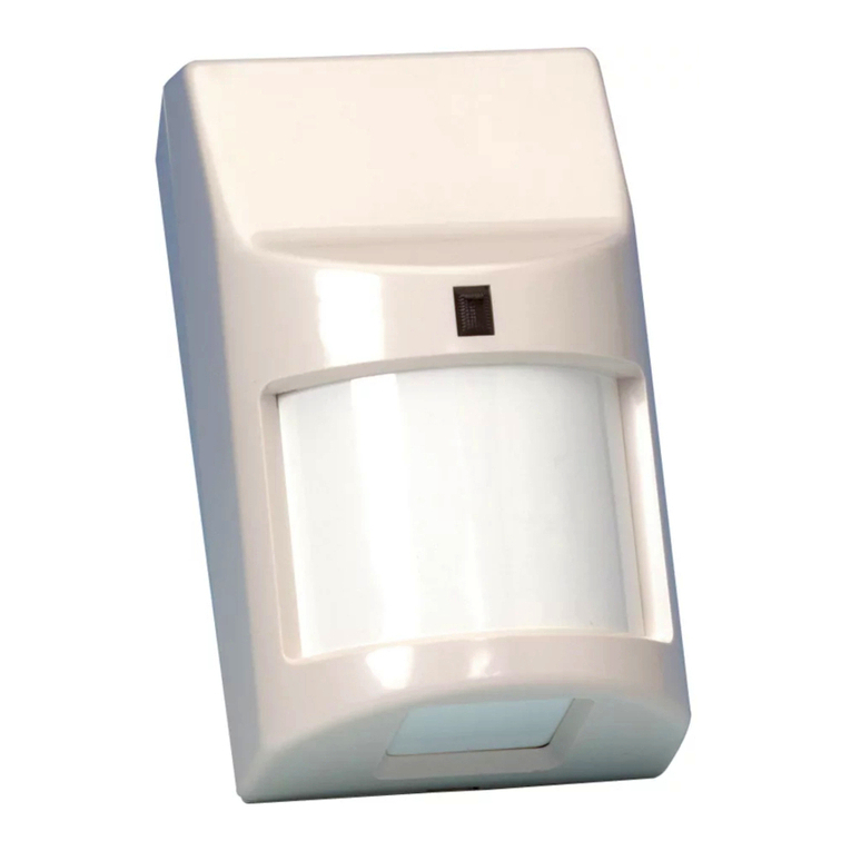
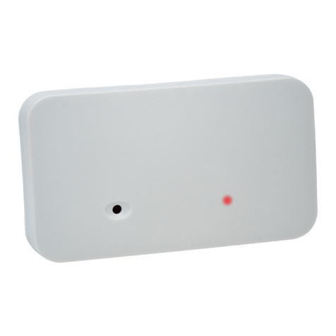
elock EL-PB60S User manual

Photoelectric Beam Detector EL-PB60 S
Features
EL-PB60S Photoelectric Beam Detector ( 60M )
Wide angle adjustment
External light protection
Protection against frost/dew, Guaranteed quality of front cover
High convenience for installation and wiring
Safety Approval: CE
Specification
Protection range: Outdoor : 60m Indoor : 120m
Detection method: Simultaneous breaking of 2 beams
Infrared beam: Double modulation pulsed beams by LED
Response time: 50 ~ 700mS
Supply voltage: DC 10.8 ~ 25VDC(Non-polarity)
Current: Max. 57mA
LED: Tx : Power(Green LED),
Rx :Sensitivity good (Green LED),
When an alarm is initiated (Red LED)
Alarm output: Dry contact relay output form C,
Contact action : Interruption time +delay time(1~3 sec),
Contact capacity : 30V(AC/DC) 1A or Less
Tamper output: Dry contact relay output form N.C(Rx only),
Contact action : Activated when cover is detached,
Contact capacity : 30V (AC/DC) 1A or Less
Temperature: -20Ԩ~ 60Ԩ
Beam Adjustment: Horizontal : 180˚(±90˚), Vertical : 20˚(±10˚)
Mounting site: Indoor/Outdoor
Material: Cover : PC resin, Base : ABS resin
Dimension: 63 x 163 x 75mm (W x H x D)
Weight: Rx : 330g, Tx : 315g
Function: Monitor jack output, Frost proof cover
IP rating: IP 44
EL-PB60S

P
U
W
d
e
a
n
P
p
r
o
f
i
m
N
1
.
P
hoto
e
U
ser Gui
d
W
e appreci
a
e
pendable
s
n
d effectiv
e
lease Not
e
r
eventing d
e
f
God (Incl
u
m
proper m
a
N
otice
The
p
The
p
speci
Do n
o
A
voi
d
Insta
l
is us
e
.
Caution
s
e
lectri
c
d
e: Inst
a
a
te your pur
c
s
ervice wh
e
e
use.
e
:This dete
c
e
vice. Mak
e
u
ding induc
t
a
intenance.
p
hotoelectri
p
hotoelectri
fication.
o
t remodel
t
d
wet or da
m
l
l inside of
v
e
d in the pl
a
s
On instal
l
c
Bea
m
a
llation I
n
c
hase of o
u
e
n properly
c
tor is desi
g
e
r is not re
s
t
ive surge
b
c beam de
t
c beam de
t
t
he detecto
m
p place.
v
isibility ran
a
ce fog occ
l
ation:
m
Dete
c
n
structi
o
u
r photoele
c
installed.
P
g
ned to det
e
s
ponsible f
o
b
y lightenin
g
t
ector is da
m
t
ector may
b
r or replac
e
ge or possi
ur frequent
c
to
r
o
n
c
tric beam
d
P
lease read
e
ct intrusio
n
o
r damage,
g
), abuse,
m
m
aged if it i
b
e damage
d
e
any parts.
ble distanc
e
ly.
d
etector. T
h
this Instru
c
n
and to ini
t
injury or lo
s
m
isuse, ab
n
s connecte
d
d
if the app
e
can see
a
h
is detector
c
tion Manu
a
t
iate an ala
r
s
ses cause
d
n
ormal usa
g
d
to an AC
lied voltag
e
a
brake ligh
t
E
will provid
e
a
l carefully
f
r
m; it is not
d
by accide
g
e, faulty in
s
power sup
p
e
exceeds t
h
t
of motor
v
E
L-PB60 S
e
long and
f
or correct
a burgla
r
-
nt, theft, A
c
s
tallation o
r
p
ly.
h
e rated
ehicle whe
n
c
ts
r
n
it

P
2
.
3
.
4
.
P
hoto
e
.
Part Des
.
Respon
s
.
Expansi
o
e
lectri
c
cription
s
e Time
o
n of Bea
m
c
Bea
m
m
and Posi
t
m
Dete
c
t
ion of Ins
t
c
to
r
t
allation
E
E
L-PB60 S

Photoelectric Beam Detector EL-PB60 S
5. Installation
6. Channel Setting
This function is used for purpose of preventing cross-talk or bypass of beams which may occur in
line protection or 2-stacked protection. Set beam channel.

P
7
.
8
.
P
hoto
e
.
Optical
A
Read vol
t
highest r
e
S
u
S
e
L
o
o
p
v
e
R
e
Ad
R
e
.
Termina
l
e
lectri
c
A
lignment
t
age from
m
e
liability.
u
pply pow
e
e
t Transmi
t
o
ok throug
h
p
posite uni
t
e
rtically (±1
0
e
ceiver sh
o
d
just the T
r
e
ceiver's h
o
l
Arrange
m
c
Bea
m
m
onitor jac
k
e
r with cove
t
ter lens to
r
h
view finde
t
is visible.
(
0
°) allowin
g
o
uld appea
r
r
ansmitter's
o
rizontally
a
m
ent
m
Dete
c
k
with volt-
m
r detached.
r
ecover len
s
r on both s
i
(
Using the
a
g
the unit to
r
on the vie
w
horizontall
y
a
nd vertical
l
c
to
r
m
eter (digita
s
by the vie
i
de and lin
e
a
djuster, th
e
work in all
w
finder of i
y
and verti
c
l
y to get hi
g
l) to confir
m
w finder.
e
-up optics
h
e
lens can
m
the directi
o
nside midd
l
c
ally to get
h
g
hest volta
g
m
optical ali
g
h
orizontally
m
ove horiz
o
o
ns). The o
p
l
e mirror.
h
ighest volt
a
g
e reading.
E
g
nment an
d
and vertic
a
o
ntally (±90
p
posite Tra
n
a
ge readin
g
E
L-PB60 S
d
to obtain
t
a
lly until th
e
°) and
n
smitter or
g
. Adjust th
e
t
he
e
e

Photoelectric Beam Detector EL-PB60 S
9. Troubleshooting
Symptom Possible cause Remedy
LED does not
light - No power supply - Turn on the power
- Bad wiring connection or broken wire, short - Check wiring
Alarm LED does
not light when
the beam is
broken
- No power supply - Turn on the power
- Bad wiring connection or broken wire, short - Check wiring
- Beam is reflected on another object and sent
into the receiver - Remove the reflecting object or
change beam direction
- Two beams are not broken simultaneously - Break two beams simultaneously
Alarm LED
continues to light - Beam alignment is out - Check and adjust again
- Shading object between Tx. and Rx. - Remove the shading object
- Optics of unit are solied - Clean the optics with soft cloth
Intermittent
alarms - Bad wiring connection - Check again
- change of supply voltage - Stabilize supply voltage
- Shading object between Tx. and Rx. - Remove the shading object
- A large electric noise source, such as power
machine, is located nearby Tx. and Rx. - Change the place for installation
- Unstable installation of Tx. and Rx. - Stabilize
- Solied optics of Tx. and Rx. - Clean the optics with a soft cloth
- Improper alignment - Check and adjust again
- Small animals may pass through the 2 beams - Set the response time longer
10.Dimensions
Limited Warranty
elock Products are warranted to be free from detect in material and workmanship for 12 months from original date
o shipment. Our warranty does not cover damage or failure caused by Acts of God, abuse, misuse, abnormal
usage, faulty installation, improper maintenance or any repair other than those provided by elock, including implied
warranties for merchantability and implied warranties for fitness are limited in duration to 12 months from original
date of shipment. During the warranty period, elock will repair or replace, at its sole option, free of charge, any
defective parts returned prepaid. Please provide the model number of product, original date of shipment and
nature of difficulty being experienced. There will render for product repairs made after our warranty period has
expired.
Table of contents
Other elock Security Sensor manuals
Popular Security Sensor manuals by other brands
DARTY
DARTY DELTA DORE installation guide

Honeywell
Honeywell GasAlert Max XT II user manual

teko
teko Astra-5131 user guide

BURG-WACHTER
BURG-WACHTER BURGsmart Protect MOTION 2012 Assembly and user manuals
Halma
Halma Apollo Marine 65 Series manual

SBS
SBS SBS-H2 Installation, operating, & maintenance instructions
