ELPRO WI-I/O 9-L-R User manual

Quick Start Guide
WI-I/O 9-L-R Wireless I/O
Receiver Unit
WI-I/O 9-L-R QuickStart v1.7

ELPRO 905U-L Wireless I/O Receiver Unit Quick Start Guide
ELPRO 905U-L Wireless I/O Receiver Unit v1.7 page 2 of 8
This document is the WI-I/O 9-L-R Wireless I/O Receiver Unit Quick Start Guide and
contains the following sections:
Section Read this section if you want to …
Basic steps for using your unit Learn the basic steps for installing and using your unit.
Factory default configuration Understand how the transmitter sends information to the receiver.
Unit components Understand the different parts of your unit.
Antenna installation Learn how to install an antenna with your unit.
Resetting factory defaults Reset your unit to the original factory default settings.
Linking transmitter and receiver units Link your units to work as a dedicated pair.
Safety information Understand important safety information related to your unit.
NOTE: You must read this information before installing your unit.
Specifications Know technical information about your unit.
For more information, see the next sections.
This document describes how to configure your unit using the default factory configuration that
lets you easily setup your network as a simple send/receive network using a dedicated pair of
transmitter and receiver units.
The basic steps for using your unit are:
1. Connect the antenna power supply and transducer signals using the instructions in
this document. Power supply and transducer connection is described in the section
Unit components and connections. Antenna connection is described in the section
Antenna installation. For more information, see the WI-I/O 9-L-x Install Manual.
2. Reset the transmitter and receiver units to the factory default configurations.
3. Link the transmitter and receiver units to work as a dedicated pair.
4. Bench test your configuration before deploying.
NOTE: You can also configure your network using a user-defined customised configuration that
lets you set specific information about your network. For more information on setting a user-
defined customised configuration, see the WI-I/O 9-L-x User Manual on the enclosed CD.
When you configure the units using the configuration in this document, the inputs from the
transmitter are sent to the outputs at the receiver as follows:
WI-I/O 9-L-T(Transmitter) Sends WI-I/O 9-L-R (Receiver)
Digital Input 1 Digital Output 1
Digital Input 2 Digital Output 2
Analogue Setpoint Digital Output 3
Analogue input (4-20 mA) Analog output (4-20 mA)
Thermocouple Input (Not used)
Setpoint Output (Local indication)
Communication Failure
(Comes on if no messages
from WI-I/O 9-L-T)
System OK (On if system OK) System OK (On if system OK)

ELPRO 905U-L Wireless I/O Receiver Unit Quick Start Guide
ELPRO 905U-L Wireless I/O Receiver Unit v1.7 page 3 of 8
Your WI-I/O 9-L-R receiver unit has the following components and terminal connections:
In order to comply with Electrical Safety Regulations, this module must be installed in an Electrical AND
Fire enclosure. This enclosure may be a single or multiple enclosures. Access to the module is to be
made by a Service Person only.
In order to comply with Electrical Safety Standards, when connecting SELV AND voltages which are
greater than SELV (30VAC or 60VDC) together, then Relay Output 2 must NOT be used in order to
provide sufficient isolation between the outputs
Max. 30VDC
500mA
+
For inductive load,
use surge diodes
+
LOAD
LOAD
-
SYSTEM OK
COMMS FAIL
COMMON
AO
-
+
POWER SUPPLY
+ 24V
ANALOG OUTPUT
Max. analog load
900 ohm
-
+
NOT USED
NOT USED
-
-
-
-
-
-
DO 3
DO 2
DO 1
DO 3
DO 2
DO 1
DO contacts are rated at 1A, 250VAC
For good engineering practice, use
a surge diode for DC loads and
a surge capacitor (10nF 250V) for AC loads
DC
LOAD
AC
LOAD
+
-
POWER
SUPPLY
9 – 30 VDC
250mA @
12V
**IMPORTANT ELECTRICAL SAFETY INFORMATION**
Earth Wire Lug
underneath Unit

ELPRO 905U-L Wireless I/O Receiver Unit Quick Start Guide
ELPRO 905U-L Wireless I/O Receiver Unit v1.7 page 4 of 8
front panel contains the following components:
The LEDs on the front panel indicate the unit status:
LED Status Indicates
None No power supply.
OK LED Green Current status of the unit OK.
OK LED Red Fault condition detected in unit.
RX Led Flashes Receiving Message.
CF Led ON Module Communication Failure Output is active.
PG LED on Configuration Cable Connected.
Output LED ON The Output LEDS (i.e. D1, D2, D3) light when the corresponding output is active.
D1 Relay output D1 is ON (Contact Closed).
D2 Relay Output D2 is ON.
D3 Relay Output D3 is ON.
LEDs with RSSI Push
Button Pressed
When you press the RSSI push button, the unit shows the signal strength by lighting
the LEDs from the bottom to the top. Signal strength is the strength of the last
message received that was addressed to this station.
LED Signal Strength LED Signal Strength
D1 More than -85 dBm RX More than -100 dBm
D2 More than -90 dBm CF More than -105 dBm
D3 More than -95 dBm PG Always on during RSSI test
Output LED flashing
quickly
If an output is in communication failure, the corresponding LED flashes at 5 Hz.
D1 Relay Output D1 is in communication failure.
D2 Relay Output D2 is in communication failure.
D3 Relay Output D3 is in communication failure.
PG Analog output is in communications failure.
SMA antenna connector
at top of unit
RSSI push-button
RS232 configuration
port

ELPRO 905U-L Wireless I/O Receiver Unit Quick Start Guide
ELPRO 905U-L Wireless I/O Receiver Unit v1.7 page 5 of 8

ELPRO 905U-L Wireless I/O Receiver Unit Quick Start Guide
ELPRO 905U-L Wireless I/O Receiver Unit v1.7 page 6 of 8
You must reset the receiver unit to factory defaults before linking the transmitter and receiver
units.
To reset the default factory configuration:
1. Press and hold the RSSI push button.
2. Power on the WI-I/O 9-L-R receiver.
3. The WI-I/O 9-L-R receiver flashes all LEDs at medium flash (i.e. 1.6 Hz).
NOTE: If the LEDs do not flash, you must repeat steps 1 and 2 until the LEDs flash before
continuing.
4. Release the RSSI push button within 5 seconds.
5. Within a further 60 seconds, press and hold the RSSI push button for 5 seconds (until
the LEDs stop flashing) and then release.
6. The WI-I/O 9-L receiver lights all LEDs for 2 seconds before returning to normal
operation.
NOTE: If the LEDs do not light, you must repeat the process from step 1 until the LEDs
light before continuing.
7. You can now link the transmitter and receiver units.
You must reset the transmitter unit to factory defaults (to disable encryption) before linking the
transmitter and receiver units. For more information, see the WI-I/O 9-L-T Transmitter Quick
Start Guide.
NOTE: You must complete the linking process in 60 seconds.
To link the transmitter and receiver units:
1. Press and hold down the RSSI Pushbutton on the receiver.
2. Power on the receiver while holding down the RSSI Pushbutton
3. Release the RSSI Pushbutton as soon as the Receiver LEDS flash (within 5 seconds
of powering the receiver).
4. The receiver will flash all LEDs for a maximum 60 seconds while it tries to link to the
transmitter.
5. Power on the transmitter. The transmitter sends a special “Link” message to allow the
receiver to recognise the transmitter.
6. When the units link, the receiver lights all LEDs for 2 seconds before returning to
normal operation.
NOTE: If the receiver LEDs continue flashing within the 60 seconds, the units are not
linked and you should retry the linking process by powering the transmitter off and on
again. If you exceed the 60 seconds, you must restart the linking process from step 1.
7. You can now bench test your configuration before deploying.

ELPRO 905U-L Wireless I/O Receiver Unit Quick Start Guide
ELPRO 905U-L Wireless I/O Receiver Unit v1.7 page 7 of 8
Thank you for selecting the WI-I/O 9-L receiver for your telemetry needs. We trust it will give you many years of
valuable service. To ensure your WI-I/O 9-L receiver enjoys a long life, double-check ALL your connections with the
user’s manual before powering on the unit.
WARNING: Incorrect termination of supply wires may cause internal damage and will void warranty.
Exposure to RF energy is an important safety consideration. The FCC has adopted a safety standard for human
exposure to radio frequency electromagnetic energy emitted by FCC regulated equipment as a result of its actions in
Docket 93-62 and OET Bulletin 65 Edition 97-01.
FCC Notice when used in USA: WI-I/O 9-L-R Module
Part Additional information
15 This device has been tested and found to comply with the limits for a Class B digital device, pursuant to
Part15 of the FCC rules (Code of Federal Regulations 47CFR Part 15). Operation is subject to the condition
that this device does not cause harmful interference.
90 This device has been type accepted for operation by the FCC in accordance with Part90 of the FCC rules
(47CFR Part 90). See the label on the unit for the specific FCC ID and any other certification designations.
Industry Canada: Wireless I/O Module
RSS-119 - This device has been type accepted for operation by Industry Canada in accordance with RSS-119 of the
Industry Canada rules. See the label on the unit for the specific Industry Canada certification number and any other
certification designations.
NOTE: Any changes or modifications not expressly approved by Weidmuller, Inc. P/L could void the user’s authority
to operate this equipment.
To operate this equipment legally the user must obtain a radio-operating license from the government agency. This is
done so the government can coordinate radio users in order to minimize interference.
Safety information - FCC Notice
This device complies with Part 15.247 of the FCC Rules. Operation is subject to the following two conditions:
This device may not cause harmful interference; and
This device must accept any interference received, including interference that may cause undesired operation
NOTE: This equipment is suitable for use in Class 1 Division 2 groups A, B and C or non-hazardous locations only.
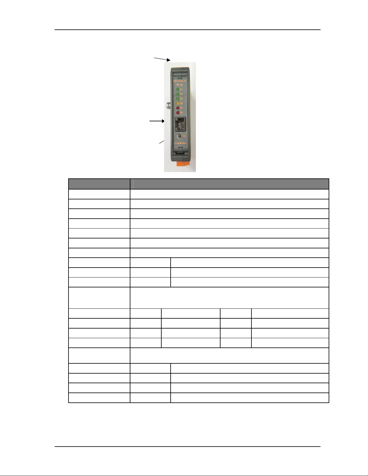
Input/output Number Additional information
Digital outputs 3 Voltage-free contacts rated at 250 VAC, 1A.
2 for digital inputs and 1 for setpoint.
Status outputs 2 Separate System OK and communication failure output.
Analog output 1 16-bit resolution, 0.1% accuracy, single-ended source output.
Power supply 1 9-30 VDC 1 Amp CSA certified Class 2 power supply. For use in
Class 1 Div 2 explosive areas, the power supply must be
approved for Class 1 Div 2 use.
WARNING: Explosion hazard - do not disconnect while circuit is
live unless area is known to be non-hazardous.
Radio receiver 1 High sensitivity FHSS UHF radio receiver.
Frequency 902 – 928 MHz Actual frequency range depends on country.
Sensitivity -110 dBm At PER 8%.

ELPRO 905U-L Wireless I/O Receiver Unit Quick Start Guide
ELPRO 905U-L Wireless I/O Receiver Unit v1.7 page 8 of 8
Document information
Quick Start Guide WI-I/O 9-L-R Wireless I/O Receiver Unit
Weidmuller, Inc. contact details
Address > 821 Southlake Blvd., Richmond, VA 23236
Telephone > (800) 849-9343
Fax > (804) 897-4135
Website > www.wireless.weidmuller.com
Limited lifetime warranty, disclaimer and limitation of remedies
Weidmuller Inc. products are warranted to be free from manufacturing defects for the “serviceable lifetime” of the
product. The “serviceable lifetime” is limited to the availability of electronic components. If the serviceable life is
reached in less than three years following the original purchase from Weidmuller Inc., Weidmuller Inc. will replace
the product with an equivalent product if an equivalent product is available.
This warranty does not extend to:
- Failures caused by the operation of the equipment outside the particular product's specification, or
- Use of the module not in accordance with this User Manual, or
- Abuse, misuse, neglect or damage by external causes, or
- Repairs, alterations, or modifications undertaken other than by an authorized Service Agent.
Weidmuller Inc.’s liability under this warranty is limited to the replacement or repair of the product.
This warranty is in lieu of and exclusive of all other warranties. This warranty does not indemnify the purchaser of
products for any consequential claim for damages or loss of operations or profits and Weidmuller Inc. is not liable for
any consequential damages or loss of operations or profits resulting from the use of these products. Weidmuller Inc.
is not liable for damages, losses, costs, injury or harm incurred as a consequence of any representations, warranties
or conditions made by Weidmuller Inc. or its representatives or by any other party, except as expressed solely in this
document.
Table of contents
Other ELPRO Receiver manuals