ElproSys DiagProg4 User manual

DIAGNOSTIC TESTER Instruction manual
© ElproSys
April, 2017 − Rev. 3.0 1
Diagnostic tester
Instruction Manual
Prepared by
:
Sylwester Czupryna
Approved by:
Sebastian Żur
ElproSys Sp. z o.o.
ul. Tarnogórska 140
44-102 Gliwice
ENGLISH

DIAGNOSTIC TESTER Instruction manual
© ElproSys
April, 2017 − Rev. 3.0 2
TABLE OF CONTENTS 1.
Table of contents ....................................................................................................................2 1.
Safety principles and rules .......................................................................................................3 2.
Preliminaries ...........................................................................................................................4 3.
The first USE ............................................................................................................................5 4.
1. Activation ................................................................................................................................5
2. Registration .............................................................................................................................5
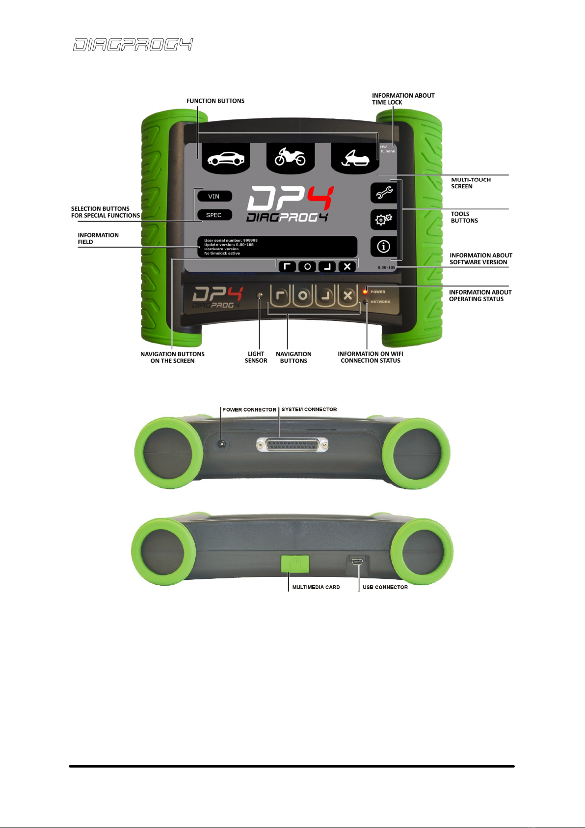
DiagProg4 - description ...........................................................................................................6 5.
Multi-touch screen ..................................................................................................................6 6.
Text and value entry ................................................................................................................7 7.
Signaling leds ..........................................................................................................................9 8.
Buttons ...................................................................................................................................9 9.
SetUP - description of functions............................................................................................ 11 10.
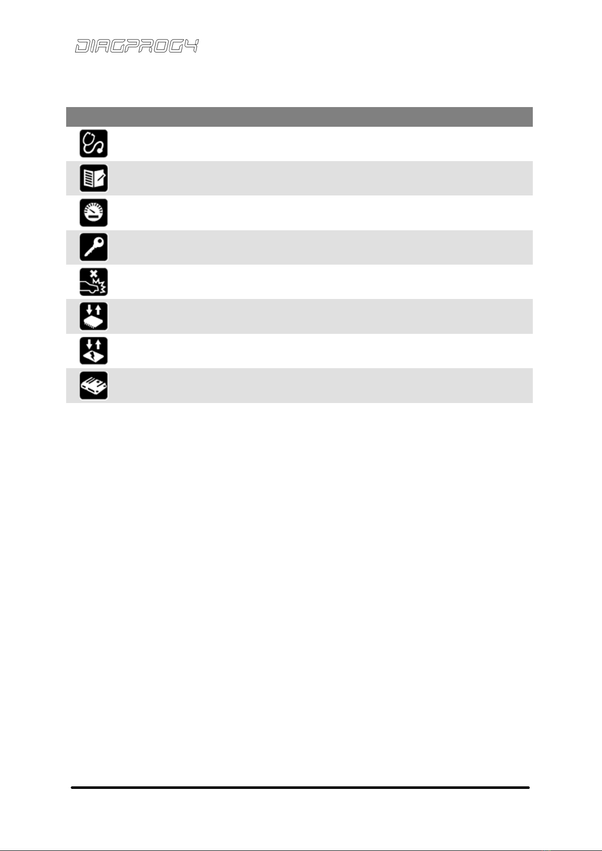
Tools - description of functions ............................................................................................. 13 11.
Power supply......................................................................................................................... 15 12.
Memory card......................................................................................................................... 16 13.
WiFi connection .................................................................................................................... 17 14.
Light sensor ........................................................................................................................... 17 15.
DiagProg4 connection with PC (USB) ..................................................................................... 17 16.
DISPLAY FIRMWARE UPDATE ................................................................................................. 18 17.
RESTART DIAGPROG4 ............................................................................................................ 18 18.
DIAGPROG4 MANAGER ......................................................................................................... 19 19.
DIAGPROG4 TEST .................................................................................................................. 20 20.
TECHNICAL DATA................................................................................................................... 21 21.
System connector features .................................................................................................... 22 22.
Compliance with standards ................................................................................................... 23 23.
TECHNICAL SUPPORT............................................................................................................. 24 24.
25. Warranty..................................................................................................................................... 25
26. Certificates ................................................................................................................................. 26

DIAGNOSTIC TESTER Instruction manual
© ElproSys
April, 2017 − Rev. 3.0 3
Thank you...
Thank you for your trust and for choosing ElproSys products.
SAFETY PRINCIPLES AND RULES 2.
Read this manual thoroughly before the first use of the device. Failure to comply with safety
regulations contained in this instruction manual may result in loss of warranty.
Only cables provided or sold by ElproSys company must be used.
The device must be protected from the rain, moisture and sunlight.
The device is not intended for use by people (including children) with compromised mental,
physical, sensory capacities or with insufficient experience or knowledge unless closely supervised
and instructed by a person responsible for their safety.
When using electrical equipment, ALWAYS comply with basic safety precautions.
The device should not be used for any other purposes than those specified in this manual.
Only authorized service center can service the unit. The warranty does not cover damages caused
by improper exploitation of the unit, failure to comply with this manual, unauthorized alterations
or repair carried out by an unauthorized person. Before cleaning, repairing or any maintenance
work, ALWAYS disconnect the unit from the power supply.
The device is intended for use both indoors and outdoors.
The device should not be exposed to excessive smoke or dust.
Do not touch the screen with a sharp object, doing so may result in malfunction or damage.
In case of a chipped or cracked touch screen, do not use the device. Any damages to the glass
screen resulting from improper handling will exclude any warranty.
The device should be cleaned with a dry and soft cloth. Do not clean the device by spraying
or immersing in water.
Disconnect the unit from the power supply before cleaning the unit or any of its part.
ATTENTION
This manual does not take into account local regulations. The user is solely responsible for the
compliance with the local regulations.
ATTENTION
Any repair work must be carried out by ElproSys company or its authorized dealer. Failure to
comply with it may result in loss of warranty.
ATTENTION
Please store this instruction manual in a safe place. If the device is passed on to another user
this manual should also be provided.

DIAGNOSTIC TESTER Instruction manual
© ElproSys
April, 2017 − Rev. 3.0 4
PRELIMINARIES 3.
Device inspection – TRANSPORT
After receiving the device make sure that it is intact and that all accessories are in place. Supplied
accessories may differ depending on the purchased software package. In case of any damage do not
use the device, but immediately contact ElproSys company or its authorized representative.
Switching on and off the device
DiagProg4 device does not have a switch. In order to switch on / off the device power cable should
be connected / disconnected.
Auto Power off
Device, will automatically switch off after 1 hour if not used. If required it can be changed to 2 or 3
hours.
Contact – Customer Service
In case of any problems with DiagProg4, please contact an authorised representative or ElproSys
company directly. Please provide serial number of the device when contacting the company. Serial
number can be found on the nameplate, at the back of the unit.
DiagProg4 Diagnostic tester – Nameplate with serial number
Serial number on the photo above is "0035BE"

DIAGNOSTIC TESTER Instruction manual
© ElproSys
April, 2017 − Rev. 3.0 5
THE FIRST USE 4.
DiagProg4 delivered to the client remains inactive and is a demo version. In order for the device
to be fully active please complete the following steps.
1. Activation
AUTOMATIC ACTIVATION
In order to activate DiagProg4 connect the device to WIFI network a select from DP4 menu:
SETUP → DOWNLOAD UPDATE/ACTIVATION
Device will automatically check for new updates/ activations on the company server and download
it on microSD card. If download succeed device will be automatically restarted.
MANUAL ACTIVATION
In order to activate DiagProg4 manually activation file (with *.dpp extension) received directly from
ElproSys company or its representative must be uploaded to the device.
2. Registration
DiagProg4 device can be registered using DIAGPROG4 MANAGER PC tool. It can be downloaded free
of charge from manufacturers website.
System requirements:
Operating system: Windows Vista, Windows 7, Windows 8, Windows 10.
RAM: 1 GB (Recommended)
Free disk space: At least 2 GB (Recommended)
Software requirements: .Net Framework 4.5 or above
ATTENTION
Submitted registration data is stored in DiagProg4. Submitted data is entered permanently - it can’t
be edited or altered. Stored data can only be altered by ElproSys employee or an authorised
representative
.

DIAGNOSTIC TESTER Instruction manual
© ElproSys
April, 2017 − Rev. 3.0 6
DIAGPROG4 - DESCRIPTION 5.
Please find below some information about DiagProg4 that will help familiarise with the product.
Table 1 - Display - technical parameters
TECHNICAL PARAMETERS
Dimensions
7’
(
165
mm
x 104.44
mm
x 6.76
mm)
Display type
TFT
Backlight
LED
Control options
Touch
Type
Colour
(2
62
thousands of colours
)
Resolution
800 x 480 px
Brightness
500
cd/m²
Temperature
Range
-
20
d
o +
55
°C
MULTI-TOUCH SCREEN 6.
Tapping, pressing with fingers — Few simple gestures is enough to fully use all the programs in the
device.

DIAGNOSTIC TESTER Instruction manual
© ElproSys
April, 2017 − Rev. 3.0 7
TEXT AND VALUE ENTRY 7.
DiagProg4 allows to enter text and numeric values according to the nature of the activities.
1. Text input is done using alphanumeric keypad.
Delete entered text
Start of a new line
Distance between characters
2. Numeric value input is done using numeric keypad.
Delete entered value
Confirm entered value

DIAGNOSTIC TESTER Instruction manual
© ElproSys
April, 2017 − Rev. 3.0 8
*Above screenshots and colours of the device may differ from the actual product.

DIAGNOSTIC TESTER Instruction manual
© ElproSys
April, 2017 − Rev. 3.0 9
SIGNALING LEDS 8.
POWER
Red li
gh
t indicates that
the unit
is connected to the power supply.
NETWORK
Indicates
Wi
Fi
network
connection.
BUTTONS 9.
Most buttons in DiagProg4 are virtual buttons on the display. Actual buttons „Top”, „Bottom”,
„Accept” and „Cancel” are located on the cover of the device.
Table 2 - Navigation buttons (on the cover)
BUTTON
FUNCTION
„Top/Front” button Button that allows to move upwards in the menu
„Accept” button Button that allows user to confirm
„Bottom/Back”
button Button that allows to move downwards in the menu
„Cancel/Return”
button
Button that allows the user to cancel or return to previous
function in the menu
In addition buttons may change its usage. In that case, information will be displayed on the screen.
Table 3 – Function buttons
BUTTON
FUNCTION
CAR Button - selection of cars/trucks
BIKE Button – selection of motorcycles
OTHERS
Button
–
selection of
special purpose vehicles
(
a
gricultural
machinery, construction machinery, snowmobiles) and
others.
SETUP Button for changing settings in DiagProg4.
TOOLS Button for running tools functions in DiagProg4.
INFO Displays information about DiagProg4 such as model number
and version.
VIN Button – allows to read the VIN number of the car
SPECIAL Button for running special functions.

DIAGNOSTIC TESTER Instruction manual
© ElproSys
April, 2017 − Rev. 3.0 10
Table 4 – Internal menu buttons
BUTTON
FUNCTION
Diagnostics Enables to run diagnostic options e.g. read and clear
trouble codes DTC, service, module identification.
Services – advanced editing Allows to make changes in service inspection (e.g. oil
change service).
Odometer/ Hourmeter
programming
Reading and writing new km values/ motohours in
modules.
Immobilizer Enables to read/program PIN code of the vehicle, it
allows to program keys.
Clear crash data Allows to clear accident data in Airbag modules
Read/Write EEPROM Allows to read and write full EEPROM content
Read/Write FLASH Enables to read and write full FLASH content
Advanced diagnostic
functions
Programing modules at the advanced level

DIAGNOSTIC TESTER Instruction manual
© ElproSys
April, 2017 − Rev. 3.0 11
SETUP - DESCRIPTION OF FUNCTIONS 10.
FUNCTION
DESCRIPTION
ACTIVE TECHNICAL SUPPORT
Sending
limits
from device
.
Provides access to all data
sent automatically to seek active technical support
DEFAULT SETTINGS
Restoring to
factory settings of the device
once
initially used
DOWNLOAD UPDATE/ ACTIVATION
Allows user to check for new updates/ activations
INFORMATION
Information about DiagProg4
LANGUAGE
Menu language selection: Polish, English, German,
French, Italian, Spanish, Portuguese, Brazilian
MAINTENANCE
File
synchronisation between device and files on the
server
OBDII/VOLTAGE TEST SETTINGS
Enable
s power supply to module
OTHER SETTINGS
Settings for:
- Key beep
- Screen saver
- Contrast
- Brightness
POWER SAVING
Enables / disables
the screen saver
SECURITY
Enable
s
/
disable
s
the PIN
code to unlock the device
(Personal Identification Number)
TESTS
Tests available for the user
WIFI SETTINGS
WIFI settings modification

DIAGNOSTIC TESTER Instruction manual
© ElproSys
April, 2017 − Rev. 3.0 12
1. Submenu INFORMATION
FUNCTION
DESCRIPTION
ABOUT DIAGPROG4
Information about DiagProg4 owner, serial number
of the device, current software version.
CONTROL NUMBER
Number required to register to customer zone
on www.diagprog4.com website
DATE/TIME Automatic information about date, time
DEVICE
LIMITS
Information about DiagProg4 time lock
AGREEMENT OF USE
Information about
DiagPro
g
4
agreement of use
IMPORT DP3 LICENSES
Enables transfer license from DiagProg3 to DiagPro
g
4
OPEN
-
SOURCE LICENSE
Information about open
–
source license
2. Submenu TESTS
FUNCTION DESCRIPTION
EXTERNAL INTERFACE TEST External interface test
CHECK SDHC CARD FAT32 SYSTEM Checking SDHC card integrity with FAT32 system
MULTIPLEX TEST
Multiplex test
ATTENTION
DiagProg4 shows Central European Time (UTC+1). Time and date may be incorrect while
staying in different time zones.
ATTENTION
If new SDHC card is used it has to be formatted in FAT32 format. Otherwise SDHC card will not
be detected by the device and it will not be used.

DIAGNOSTIC TESTER Instruction manual
© ElproSys
April, 2017 − Rev. 3.0 13
TOOLS - DESCRIPTION OF FUNCTIONS 11.
F
UNCTION
DESCRIPTION
CAN ANALYZER (Internal use only)
Programs For Internal Use Only
CAN PLAYER (Internal use only)
Programs For Internal Use Only
CAN TERMINATION CONTROL
Enables/ disables High Speed CAN Termination
DOWNLOAD UPDATE/ ACTIVATION
Allows user to check for new updates/
activations
EEPROM PROGRAMMER
Write EEPROM memory
EXTERNAL UNIT
POWER
Power
supply
connection
to the module
HEXEDITOR
File editing in hexadecimal system
J1850 ANALYZER (Internal use only)
Programs For Internal Use Only
K
-
L ANALYZER (Internal use only)
Programs For Internal Use Only
MICROCONTROLLER PROGRAMMER
Write FLASH + EEPROM
RESTART DIAGPROG4
Immediate restart in order to reload operating
system
RESTORE THE BACKUP MODULE
Restore backup file saved on SD card

DIAGNOSTIC TESTER Instruction manual
© ElproSys
April, 2017 − Rev. 3.0 14
SENDING LOG FILE
Send *.LOG file to ElproSys server for technical
support
SUPPORT SCRIPT
Runs support script prepared for user by
technical support team
UDS COMMUNICATION CONTROL Enables/ disables UDS communication
UNIT CALCULATOR Enables metric conversion

DIAGNOSTIC TESTER Instruction manual
© ElproSys
April, 2017 − Rev. 3.0 15
POWER SUPPLY 12.
Recommended power supply voltage for the device is 12V. Power supply socket is located in the
upper right corner of the unit.
Table 5 – Basic power supply specifications
DESCRIPTION
Recommended
power supply voltage
12V
DC
P
ermissible
power supply
voltage range
8
–
18VDC
Maximum current consumption
(without supported devices) 2A
T
hickness of the socket pin
2,50 x 5,50 mm
Polarisation of the plug/socket
(+) inside
For more detailed information on power supply please go to “Technical data” section on page 21
Picture below shows correct power supply connection to DiagProg4 together with programming
module / odometer while working on a workbench.
Pictures show INCORRECT power supply connection to DiagProg4 while programming module /
odometer when working on a workbench.

DIAGNOSTIC TESTER Instruction manual
© ElproSys
April, 2017 − Rev. 3.0 16
MEMORY CARD 13.
DiagProg4 supports microSDHCTM memory cards with the capacity of a minimum 4GB and up
to 32GB. It is recommended to use only memory card provided by ElproSys or its authorized dealer.
The use of different memory card may result in loss or damage of stored data.
In order to insert memory card:
Memory card socket is located at the bottom of the device as shown on the photo below. Insert
memory card into the slot, ensuring that the gold contacts are facing upwards and close the lid on
the slot.
Before using the machine for the first time SDHC card has to be formatted with FAT32 system
ATTENTION
If new SDHC card is used it has to be formatted in FAT32 system. Otherwise SDHC card will not
be detected by the device and it will not be used.
ATTENTION
ElproSys company is not liable for losses resulting from misuse of the damaged memory card
including loss of data.
WARNING
It is not recommended to insert or remove memory card while DiagProg4 is still switched on.
Otherwise memory card and data stored on the card may get damaged.

DIAGNOSTIC TESTER Instruction manual
© ElproSys
April, 2017 − Rev. 3.0 17
WIFI CONNECTION 14.
Wi-Fi function enables to connect to Wi-Fi network access point and provides Internet access. Wi-Fi
network provides fast Internet access within the range of a wireless access point. Information about
selected WiFi network is stored on SDHC card. Information will not be saved if SDHC card is not
inserted.
This device uses non-harmonized frequency and is intended for use in all European countries.
LIGHT SENSOR 15.
Ambient light sensor allows to automatically adjust operating parameters of the display ensuring its
optimal performance and comfort.
DIAGPROG4 CONNECTION WITH PC (USB) 16.
In order to connect DiagProg4 to a PC ( configuration) cable with mini USB plug and maximum length
of 1.5 m should be used.
Once connected to a PC DiagProg4 is automatically detected by PC operating system.
WARNING
Do not disconnect USB cable if DiagProg4 device is still connected to a PC.

DIAGNOSTIC TESTER Instruction manual
© ElproSys
April, 2017 − Rev. 3.0 18
DISPLAY FIRMWARE UPDATE 17.
Display firmware update is downloaded automatically.
User has to select from DP4 menu:
SETUP → OTHER SETTINGS → TFT Update
Estimated installation time : around 1 minute
After successful firmware update icon will no longer be displayed on the screen.
RESTART DIAGPROG4 18.
If the device screen does not respond to touch, it is possible to restart it to restore its efficiency.
Press and hold buttons - up and - cancel for at least 3 seconds to restart DiagProg4 device.
IMPORTANT:
Do not turn off power supply before finishing update.

DIAGNOSTIC TESTER Instruction manual
© ElproSys
April, 2017 − Rev. 3.0 19
DIAGPROG4 MANAGER 19.
DIAGPROG4 MANAGER – PC tool
DIAGPROG4 MANAGER connects DiagProg4 with PC, allowing data synchronisation between devices.
Software used to manage device using PC.
DiagProg4 connection with PC:
It is required to use mini USB cable supplied by manufacturer in order to connect DiagProg4 with PC.
DiagProg4 should be connected to an additional power source.
Software update
Use
this
option
to
download
latest
update and
activations from Elprosys server.
File
synchronization
Use this option to download
necessary
data files
(BSI, Flash, etc.) from Elprosys server
Technical
support
Use this option to send data
-
like LOG file,
activation status etc. required to seek technical
support
M
icroSD
card manager
Use this option to view memory card data
Info about
DiagProg4
Use
this
option
to view
device
details
Info about
DiagProg4 Manager
Use this
option
to
view
information
about
DiagProg4 Manager
System requirements:
Operating system: Windows Vista, Windows 7, Windows 8, Windows 10.
RAM: 1 GB (Recommended)
Free disk space: At least 2 GB (Recommended)
Software requirements: .Net Framework 4.5
o
r
above

DIAGNOSTIC TESTER Instruction manual
© ElproSys
April, 2017 − Rev. 3.0 20
DIAGPROG4 TEST 20.
EXTERNAL INTERFACE TEST
Diagprog4 user can use professional tester in order to test I/O lines. It can easily check its proper
functioning.
In order to do that please connect tester to system connector and also connect power supply.
Select following option from DP4 menu:
SETUP → TESTS → EXTERNAL INTERFACE TEST
The final stage of the test is shortened or extended report of protocols from measurements
and a summary with recommended further actions.
In case of any
error while performing an external interface test we recommend
contacting an Elprosys representative or company directly.
Other manuals for DiagProg4
3
Table of contents
Other ElproSys Medical Equipment manuals