InterTest V Series User manual

V Series Veterinary
Endoscope
Operation Manual


Warranty
We guarantee that the following products will be free from defects in material and
workmanship for:
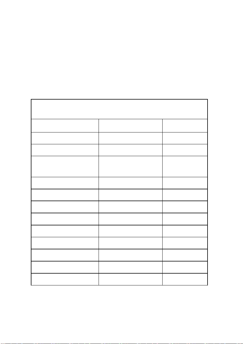
●Rechargeable Screen Handle: 1 year from the date of purchase
●Flexible insertion tube: 1 year from the date of purchase
●During the designated period, at our option, we will repair or replace any parts or
the product found to be defective free of change.
● Service, repair, or modification is carried out by us or any personnel authorized by
us.
● Our products are used in proper manner in strict compliance with operating
instructions.
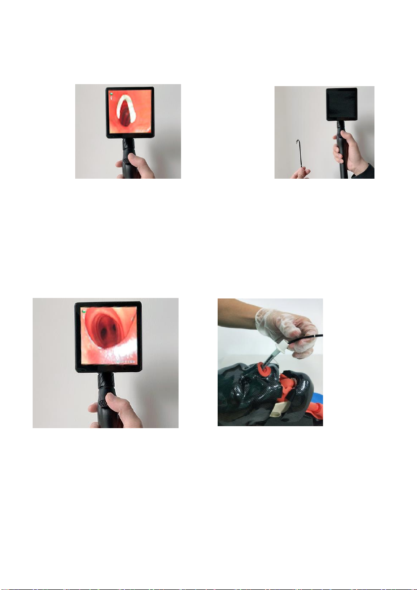
1. Product Introduction
1-1 Indication for Use
The product is intended for use as below:
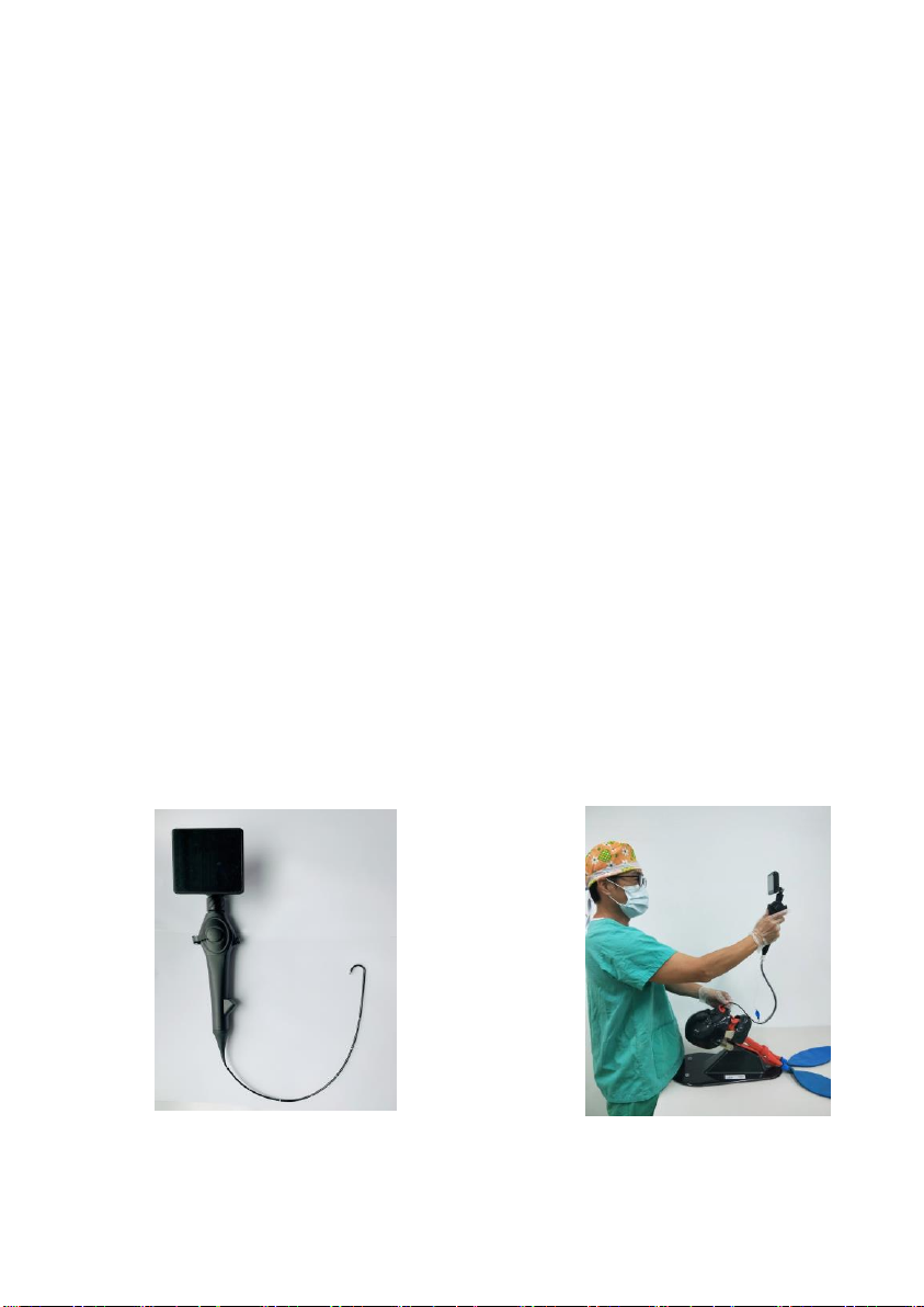
⚫Aid in endotracheal intubation.
⚫For ENT observation.
⚫Teaching purposes.
⚫Protective intubating from patient.
1-2 Contraindications
The product is not recommended for use in patient with following:
⚫Foreign body is in the airway.
⚫Needs for emergency intubation.

2. Description
The whole set consists of the following main parts:
⚫Outer diameter:
□2.8 mm
□3.8 mm / 1.2mm
□4.8 mm / 2.2mm
□5.2 mm / 2.4mm
□5.8 mm / 2.6mm
⚫Length: 60cm.
⚫Material: Aluminum alloy / Medical grade plastic
⚫Light source: White LED, brightness ≥ 3000 LUX.
⚫Camera: 160,000 pixels/ 400 x 400.
⚫Display: 4.0” LCD. 480*480
⚫Waterproof for probe: IP67.
⚫Photos, video recording, and record storage.
⚫Rotation angle: (horizontal) ≥100°/ (vertically)
≥120°.
⚫Built-in 16G memory card.
⚫Battery specifications: 3.3V ± 10% lithium
2000mAh.
⚫Power supply: Input AC 100V~240V /
Output DC 5V, 1A

3. Before use
3-1 Unpacking
Take out all items from the case, and carry out the following:
⚫Check if there are any parts missing. (See Table 1).
⚫Inspect parts for damage.
⚫Report damage or shortage to the local distributor, if any.
List of Accessories
Item
Description
Quantity
Case
Metal case
1
Rechargeable Screen
4.0’’ LCD Screen
1
Flexible Video Intubation
Handle with flexible
built-in camera
1
Mini HDMI
1
USB cable
1
Adaptor
1
Sphygmomanometer
1
Cleaning brush
2
Plastic Tee
1
Protect cover
1
Leak proof pressure joint
1
Rubber stopper
1
Table1

3-2 Charging
⚫Plug the power cord into the USB port on the side of the screen. (Fig. 1).
⚫Blue light indicator means charging.
⚫The green light turns on when fully charged.
Fig.1
3-3 Installation
⚫Connect the flexible intubation with the screen, and
ensure groove alignment (Fig. 2).
⚫Lock the flexible intubation with spiral ring (Fig.3).
Fig 2 Fig 3
3-4 Function test
⚫Power button: Power on/off (one second: on/two seconds: off).
⚫Up and Down button: Confirm the option.
⚫Setting Button: Menu mode

⚫Photo/Video recording button on the handle:
1). One click to take photo
2). Press and hold to record
3). One click again to stop recording
3-5 Setting
After Press Setting button, you will see the Screen on the following:
○
1Time Setting: select the up/down button and setting button to set the right
time
○
2Auto Shut Down: you can select the time 1minute, 3 minutes, 5 minutes

Automatic shut down when the device without operation
○
3File Formatting
Caution: please save your file before you selected this function.
○
4FW updated: You can use this function when update the system
3-6 Menu and Function
When the device is on ad you touch the screen, you will see the following:
①.Lightness Adjusting: Touch icon to adjust the lightness by referring the level from
②.Zoom: touch the icon and zoom by referring the level from
③.Photo Shooting
④.Video Recording
⑤. Image Review
⑥. Video Review
⑦. Setting Icon: Same as setting button

⑧. Lightness states
⑨. Zoom states
⑩/⑪. Date/time
⑫. SD Card
⑬. Battery
⑭. Image mirror
⑮. Image effect
⑯. RGB regulation
⑰. White balance
⑱. Image freeze
⑲. Flash lighting
4. Operating Instructions
Connect the flexible video intubation and the screen, and then lubricate the stylet.
(Fig. 4)
Insert the flexible stylet from the oral cavity or nasal cavity slowly and observe the
condition. (Fig.5)
Fig. 4
Fig.5

When the epiglottis appears on the screen, adjust the angle of the flexible stylet
and then advance the stylet through the vocal cords. (Fig. 6 & 7)
Fig. 6 Fig.7
Observe the condition on the screen, and insert the endotracheal tube. (Fig. 8 & 9)
Fig. 8
Fig. 9

5. Cleaning and Disinfection
Method
Flexible video intubation
Wipe with a gauze pad with 75%
alcohol
O
Enzymatic Cleaning Solution
O
Glutaraldehyde 2% solution -
Cidex
O
Ethylene Oxide Gas (E.O.)
X
Autoclave
X
6. Service
There is no user serviceable parts inside the qualified screen handle, which has
passed performance tests and quality assurance tests and meet qualification criteria
prior to shipment. No calibration is required, and please do not open any part of the
products. We will be held responsible for damage only when service, repair,
readjustment or modification needs to be carried out by us or any personnel authorized
by us.
7. Troubleshooting
Problem
Cause
Solution
Rechargeable
Screen Handle
failure
Battery level low
Charging
Oxidation of contact surfaces
Clean the contact
Poor contact between
Stylet/laryngoscope and handle
Tighten both parts

Data transfer
failure
Loose connection
Check whether the
cable’s firmly connected.
Blurred image
Len stains
Clean the lens
Important: After trying all above solutions but the problems remain, please
contact the local distributor.
8. Specification
Display
part
Display
4 inch IPS Full view display
Display resolution
480*480
Operation
interface
Capacitive touch and key double-set
co-operation
Image control
Continuous (4 times)
Image format
JPEG/JPG
Software upgrade
TF card upgrade
Video format
AVI
Function
Photos, videos, playback, etc.
File management
Picture/video playback, deletion, formatting
Storage
16G Maximum expansion 32G SD card
Data I/O port
SD card, HDMI video signal, USB
Battery working
hours
6h
Brightness
adjustment
6 level brightness adjustment
Operation
Camera pixels
30W digital imaging

9. General Information
9-1 Safety Standards
Safety requirements
Meets the requirements of GB9706.1-2007 and GB9706.19-2000
Electromagnetic compatibility (EMC)
Meets the requirements of YY0505-2012 and GB9706.19-2000.
Environmental requirements
Meet the requirements of climatic environmental test group II, mechanical
environmental test group II, transportation test and adaptability to power supply.
9-2 Operation/storage/transport conditions
Operating conditions
part
Optional insertion
tube
Distal end outer diameter | Channel inner
diameter
2.8mm / none
3.8mm / 1.2mm
4.8mm / 2.2mm
5.2mm / 2.4mm
5.8mm / 2.6mm
Insertion tube lens
view
Two way adjustment
Foreign body
forceps
700mm/1200mm(Optional)

Ambient temperature: -5ºC ~ 40ºC
Relative humidity: ≤80% (no condensing)
Atmospheric pressure: 700hPa ~ 1060hPa
Never place it in direct sunlight or near any other source of cold or heat.
Storage and transportation conditions
Ambient temperature: -20 ° C ~ +55 ° C
Relative humidity: ≤93%
9-3 Annex
Annex: 1
Guidance and manufacturer’s declaration ---electromagnetic emissions
Video intubation set is intended for use in the electromagnetic environment
specified below. The customer or the user of the device should assure that the device is
used in such an environment.
Emissions test
Compliance
Electromagnetic environment--guidance
RF emissions
GB 4824
Group 1
Video intubation set uses RF energy
only for its internal function. Therefore, its
RF emissions are very low and are not likely
to cause any interference in nearby
electronic equipment.
RF emissions
GB 4824
Class A
Video intubation set can be applied
with all establishments other than domestic

Harmonic Emissions
GB 17625.1
NA
and those directly connected to a low
voltage power supply network which
supplies buildings used for domestic
purposes.
Voltage
Fluctuations/Flicker
Emissions
GB 17625.2
NA

Annex: 2
Guidance and manufacturer’s declaration—electromagnetic immunity
Video Intubation Set is intended for use in the electromagnetic environment
specified below. The customer or the user of the device should assure that the
device is used in such an environment.
Immunity
Test
IEC 60601 Test
level
Compliance
level
Electromagnetic
environment-guidance
Electrostatic
discharge
GB/T
17626.2
±6 kV contact
±8 kV air
±6 kV contact
±8 kV air
Floors should be wood,
concrete or ceramic tile. If
floors are covered with
synthetic material, the
relative humidity should
be at least 30%.
Electrical
fast
transient/bu
rst
GB/T
17626.4
±2kV for power
supply lines
±1kV for
input/output lines
NA
Mains power quality
should be that of a typical
commercial or hospital
environment.
Surge
GB/T
17626.5
±1 kV differential
mode
±2 kV common
mode
NA
Mains power quality
should be that of a typical
commercial or hospital
environment.

Annex: 3
Guidance and manufacturer’s declaration—electromagnetic immunity
Video Intubation Set is intended for use in the electromagnetic environment
specified below. The customer or the user of the device should assure that the
device is used in such an environment.
Immunity
Test
IEC 60601 Test
level
Compliance
level
Electromagnetic
environment-guidance
Voltage
dips, short
interrupti
ons and
voltage
variations
on power
supply
input lines
GB/T
17626.11
<5 % UT(>95%
dip in UT) for 0.5
cycle
40 % UT(60% dip
in UT) for 5 cycles
70 % UT(30% dip
in UT) for 25
cycles
<5 % UT(>95%
dip in UT) for 5
sec
NA
Mains power quality should be that
of a typical commercial or hospital
environment.
If the user of the device requires
continued operation during power
mains interruptions, it is
recommended that the device be
powered from an uninterruptible
power supply or a backup battery
system.
Power
frequency
(50/60H
z)
GB/T
17626.8
3A/m
3A/m
Power frequency magnetic fields
should be at levels characteristic of
a typical location in a typical
commercial or hospital
environment.
Note: UTis the AC mains voltage prior to application of the test level.

Annex: 4
Guidance and manufacturer’s declaration—electromagnetic immunity
Video Intubation Set is intended for use in the electromagnetic environment
specified below. The customer or the user of the device should assure that the
device is used in such an environment.
Immun
ity Test
IEC 60601
Test level
Complianc
e level
Electromagnetic
environment-guidance
Conduct
ed RF
GB/T
17626.6
Radiate
d RF
GB/T
17626.3
3 V(Effective
value)
150 kHz~80
MHz
3 V/m
80 MHz~2.5
GHz
NA
3 V/m
Portable and mobile RF communications
equipment should not be used any
closer to any part of the device,
including cables, than the
recommended separation distance
calculated from the equation applicable
to the frequency of the transmitter.
Recommended separation distance:
d = [3.5/V1]
p
d = 1.2
p
80 MHz~800 MHz
d = 2.3
p
800 MHz~2.5 GHz
P
—the maximum output power
rating of the transmitter in watts
(W) according to the transmitter
manufacturer;
d—the recommended

Annex: 4-(continue)
Guidance and manufacturer’s declaration—electromagnetic immunity
Immunity
Test
IEC 60601 Test
level
Compliance
level
Electromagnetic
environment-guidance
separation distance in
meters (m).
Field strengths from fixed RF
transmitters, should be less than
the compliance level in each
frequency range.
Interference may occur in
thevicinity of equipment marked
with the following symbol:
NOTE 1 At 80 MHz and 800 MHz, the higher frequency range applies.
NOTE 2 These guidelines may not apply in all situations. Electromagnetic
propagation is affected by absorption and reflection from structures, objects and
people.
a. Field strengths from fixed transmitters, such as base stations for radio
(cellular/cordless) telephones and land mobile radios, amateur radio, AM and
FM radio broadcast and TV broadcast cannot be predicted theoretically with
accuracy. To assess the electromagnetic environment due to fixed RF
transmitters, an electromagnetic site survey should be considered. If the
measured filed strength in the location in which the device is used exceeds the
applicable RF compliance level above, the device should be observed to verify
normal operations. If abnormal performance is observed, additional measures
may be necessary, such as reorienting or relocating the device.
b. Over the frequency range 150 kHz to 80 MHz, filed strengths should be less than
[V1] V/m.

Annex: 5
Recommended separation distances between portable and mobile RF
communications equipment and the device
Video intubation set is intended for use in an environment in which radiated RF
disturbances are controlled. The customer or the user of the device can be help
prevent electromagnetic interference by maintaining a minimum distance between
portable and mobile RF communications equipment(transmitters) and the device
as recommended below, according to the maximum output power to the
communications equipment.
Rated
maximum
output power
of transmitter
(W)
Separation distance according to frequency of transmitter(m)
150 kHz ~80MHz
d = [3.5/V1]
p
80MHz ~800MHz
d =
P2.1
800 MHz~
2.5 GHz
d =
P3.2
0.01
NA
0.12
0.23
0.1
NA
0.38
0.73
1
NA
1.2
2.3
10
NA
3.8
7.3
100
NA
12
23
Table of contents