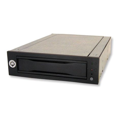
---Front Panel--- (see picture D)
---Rear View--- (see picture F)
D.1--- Reset Switch for buzzer alarm
and over- heating LED
When overheating occurs(default setting is 60 ) the buzzer℃
alarms and the temperature LED turns red, meanwhile, buzzer
is alarming and LED is blinking). Press the Reset Switch to stop
the alarm, and LED goes off.
D.2--- D.4 (HD1〜HD3, Power SW and LED): Power
on, LED indicates Green. Orange color blinking for HDD
access)
D.5--- Fan sensor LED: LED indicates Green when
powered on. When fan failed, LED turns Red.
D.6--- Carrier Safety Lock
The safety lock safeguards the hard disks in the correct
position and prevents it bouncing out while HDD is
working. (see Picture E).
Rear View Description (Picture F):
POWER1: 4pin Power connector
POWER2: 15pin Serial ATA Power connector [ Two types power for
connection (4pin power & 15pin SATA power). Use the 4pin power
connector, or the 15pin power connector. (Note: Can mix using 4pin
and 15pin powers. Suggestion: At least 2 power).).
HD1— HD3: 7pin Serial ATA Signal connector
lJP1: Temperature setting jumper (default setting is 60℃)
lJP3: Extension function jumpers (see left chart)
FLEDR: Fan failure detection (red)
FLED+: Fan failure detection (+)
FLEDG: Fan failure detection (green)
RESET: Reset Switch for buzzer alarm and Overheating LED
TLEDR: Temperature detection (red) 5V+: 5V Power
TLEDG: Temperature detection (green) GND:Grounded
J4: Fan High/Low switch [ [High 3000rpm & LOW 2300 rpm ]
LED Switch
a) When LED switch is set to “enable “position”, LED indicates Green
when powered on and Orange color blinking for HDD accessing
[ In this case, the HDD does not spin up until the SATA initial
signal is received ].
b) When LED switch is set to “disable” position, LED always indicates
SOLID GREEN both for HDD being powered on and HDD being
accessing. [ In this case, the hard drive is spinning up when the
system power is turned on ].
Picture E
